door lock CITROEN CX 1988 Service Manual
[x] Cancel search | Manufacturer: CITROEN, Model Year: 1988, Model line: CX, Model: CITROEN CX 1988Pages: 648, PDF Size: 95.8 MB
Page 17 of 648
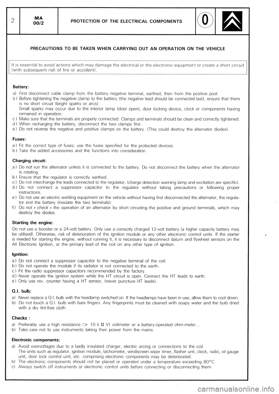
PROTECTION OF THE ELECTRICAL COMPONENTS
PRECAUTIONS TO BE TAKEN WHEN CARRYING OUT AN OPERATION ON THE VEHICLE
It is essential to avoid actrons which may damage the electrical or the electronic equipment or create a short circuit
(wrth subsequent risk of fire or accident).
Battery:
a) First disconnect cable clamp from the battery negative terminal, earthed, then from the positive post.
b 1 Before tightening the negative clamp to the battery (the negative lead should be connected last), ensure that there
is no short circuit (bright sparks or arcs).
Small sparks may occur due to the interior lamp (door open), door locking device, clock or components having
remained in operation.
c 1 Make sure that the terminals are properly connected. Clamps and terminals should be clean and correctly tightened.
d ) When recharging the battery, disconnect the two clamps first.
e) Do not reverse the negative and positive clamps on the battery. (This could destroy the alternator diodes).
Fuses:
a 1 Fit the correct type of fuses: use the fuses specified for the protected devices
b 1 Take the added accessories and the functions into consideration.
Charging circuit:
,a 1 Do not run the alternator unless it is connected to the battery. Do not disconnect the battery when the alternator
is rotating.
b 1 Ensure that the regulator is correctly earthed.
c ) Do not interchange the leads connected to the regulator, (charge detection warning lamp and excitation are specific).
d ) Do not connect a suppressor capacitor to the regulator without taking precautions or following proper
instructions.
e 1 Do not use an electric welding equipment on the vehicle without having first disconnected the alternator, the regula-
tor and the battery (insulate the two terminals).
f 1 Do not R check )) the operation of an alternator by short circuiting the positive and ground terminals, which may
destroy the diodes.
Starting the engine:
Do not use a booster or a 24-volt battery. Only use a correctly charged 12-volt battery (a higher capacity battery may
be utilised). Otherwise, risk of deterioration of the ignition module or any other electronic control units. If the starter
is needed for starting the engine, without running it, it is necessary to disconnect datum and flywheel sensors on the
All Electronic Ignition, or the primary lead of the coil on any other type of ignition.
Ignition:
a 1 Do not connect a suppressor capacitor to the negative terminal of the coil.
b 1 Do not operate the module if its radiator is not connected to the earth.
c 1 Fit the radio suppressor capacitors recommended by the factory.
d 1 Never operate the ignition system while the HT circuit is open. Connect the HT leads to earth
e) Only use rev. counter having a HT sensor, (never puncture HT leads).
0.1. bulb:
a) Never replace a 01. bulb with the headlamp switched on. If the headlamps have been in use, allow them to cool down.
b) Do not touch a 0.1. bulb with bare fingers. Any fingerprints must be cleaned with soapy water and the bulb dried
with a dry lint-free cloth.
Checks :
a) Preferably use a high resistance (> 10 k Q VI voltmeter or a battery-operated ohm-meter
b) Take care not to use instruments taking their power from the mains.
Electronic components:
a) Avoid overvoltages due to a badly insulated charger, electric arcing or connections to the coil.
The units such as regulator, ignition module, tachometer, windscreen wiper timer, flasher unit, clock, radio, oil gauge
unit, door lock control unit, etc. comprising electronic components may be deteriorated.
b) The electronic components should not be placed or operated under a temperature exceeding 80°C.
c) Always switch off instruments or electronic control units before connecting or disconnecting them.
‘
Page 19 of 648
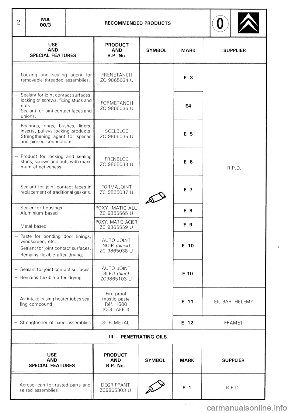
RECOMMENDED PRODUCTS
AND SUPPLIER
SPECIAL FEATURES
-- Lockrng and sealrng agent for FRENETANCH
removable threaded assemblies.
ZC 9865034 U
nuts. FORMETANCH
ZC 9865036 U
- Sealant for oint contact faces an
- Bearings, rings, bushes, liners,
inserts, pulleys locking products.
Strengthening agent for splined ZC 9865035 U
-- Product for locking and sealing
studs, screws and nuts with maxi-
ZC 9865033 U
mum effectiveness.
- Sealant for joint contact faces in FORMAJOINT
replacement of traditional gaskets. ZC 9865037 U
- Paste for bonding door linings,
windscreen, etc. AUTO JOINT
Sealant for joint contact surfaces.
ZC 9865038 U
- Sealant for joint contact surfaces. AUTO JOINT
- Remains flexible after drying.
- Air intake casing heater tubes sea-
ling compound Ets BARTHELEMY
SCELMETAL FRAM ET
III - PENETRATING OILS
AND SUPPLIER
SPECIAL FEATURES
- Aerosol can for rusted parts and DEGRIPPANT
seized assemblies ZC9865303 U
Page 388 of 648
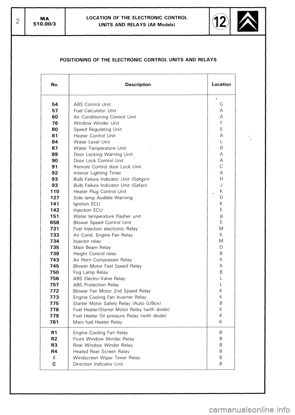
2 MA LOCATION OF THE ELECTRONIC CONTROL
510.00/3
UNITS AND RELAYS (All Models)
POSITIONING OF THE ELECTRONIC CONTROL UNITS AND RELAYS
No. Description Location
54 ABS Control Unit G
57 Fuel Calculator Unit A
60 Air Conditioning Control Unit A
76 Window Winder Unit F
80 Speed Regulating Unit E 81
Heater Control Unit A
84 Water Level Unit L
87 Water Temperature Unit B
89 Door Locking Warning Unit A
90 Door Lock Control Unit A 91
Remote Control door Lock Unit C
92 Interior Lighting Timer A
93 Bulb Failure Indicator Unit (Salopn) H
93 Bulb Failure Indicator Unit (Safari) J 110
Heater Plug Control Unit
,. K 127
Side lamp Audible Warning D 141
Ignition ECU K 142
Injection ECU E 151
Water temperature Flasher unit B 658
Blower Speed Control Unit E 731
Fuel Injection electronic Relay M 733
Air Cond. Engine Fan Relay K 734
Injector relay M 735
Main Beam Relay D
739 Height Control relay B 743
Air Horn Compressor Relay K 745
Blower Motor Fast Speed Relay A 750
Fog Lamp Relay
6 756
ABS Electra-Valve Relay L 757
ABS Protection Relay L 772
Blower Fan Motor 2nd Speed Relay K 773
Engine Cooling Fan lnverter Relay K 775
Starter Motor Safety Relay (Auto G/Box) B 778
Fuel Heater/Starter Motor Relay (with diode) K
779 Fuel Heater Oil pressure Relay (with diode) K 781
Main fuel Heater Relay K RI
Engine Cooling Fan Relay B R2
Front Window Winder Relay 6 R3
Rear Window Winder Relay B R4
Heated Rear Screen Relay 6 I
Windscreen Wiper Timer Relay
B
C Direction Indicator Unit B
Page 392 of 648
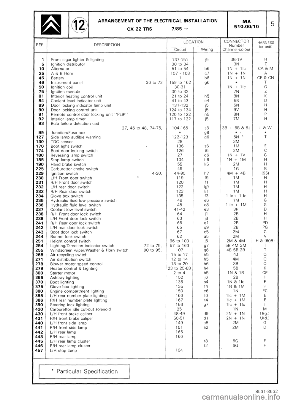
ARRANGEMENT OF THE ELECTRICAL INSTALLATION
q @ CX22TRS 7/85-t 1 MA 5 510.00110
3EF. DESCRIPTION LOCATION
Circuit Wiring CONNECTOR
Number HARNESS
Channel-colour (or urilt)
1 Front cigar ljghter & lighting 137-151
i5 38-l v H
5 Ignition distributor 30 to 34 3N 2
10 Alternator 51 to 54 b6 IN + Ilc CA & M
25 A & B Horn 107 - 108 c7 1N + 1N A
45 Battery 1
b8 IN + IN CP & CN
46 Instrument panel 36 to 73 159 to 162 g6 * T
50 Ignition coil 30-3 1 IN + Ilc G
75 Ignition module 30 to 32 7N Z
81 Interior heating control unit 21 to 24 h5 8N K
84 Coolant level indicator unit 41 to 43 e4 5B D
89 Door locking indicator lamp unit 131-132
i5 5N H
90 Door locking control unit 124 to 134 15 9v H
91 Remote control door locking unit “PLIP” 120 to 122 n5 8N P
92 Interior lamp timer 117 to 122 15 7M H
93 Bulb failure detection unit
27, 46 to 48, 74-75, 104-I 65 S8 38 + 68 & 6J L & w
95 Junction/Fuse box
127 Side lamp audible warning 1222123 g8
g6 5+N‘” ;
130 TDC sensor 28 3M
170 Boot light switch 136 s6 IM E
174 Boot door locking switch 126 t5 2M C
180 Reversing lamp switch 27 d6 1N + 1V G
185 Stop lamp switch 104 h6 IN + IM H
190 Hand brake switch 55 k5 2M H
!25 Carburettor choke switch 49 IG B
!29 Ignition switch 4-30, 44-95 h7 4M + 48 (95)
!30 L/H Front door switch *
119 f9 IM H
!31 R/H Front door switch 120 fl 1M H
!32 L/H rear door switch 122
k9 IM H
!33 R/H Rear door switch 123 kl IM H
!34 Glove box switch 135 f3 1 Ic+ 1 Ic H
!35 Hydraulic fluid low pressure switch 46 e6 IM G
!36 Hydraulic fluid level switch 45 e8 1 Ic + IM G
!37 Coolant low level switch 41-42 e3 3R D
!38 R/H Front door lock switch 64
jl 28 H
!39 L/H Front door lock switch 63 P
28 H
!41 R/H Rear door lock switch 66 (71 28 PD !42 L/H rear door lock switch 65 qg 28 PG
!43 Boot door lock switch 67 c5 2M C
!44 Bonnet lock switch 62 a5 2M V
!51 Height control switch 96 to 100
j5 2M & 4M H & (608) !54 Lighting/Direction indicator switch 72 to 75. 57 to 163 97 58 4M 3M T
!55 Windscreen wiper/Washer & Horn switch 90 to 95, 107 g6 48 5B 28 T
!68 Air recycling switch 15 to 17
h5 4J Q
!71 Air distribution switch 12 to 14 h5 4M Q !78 Blower motor speed control 18 to 20 h6 38 Q
!79 Heater control & Lighting 23 to 25-68 h4 58 K
100 Starter motor 2 to 4 b5 IN & IR CP 165 Ashtray lighting 152 if5 2B H
I70 Boot lighting 136 s4 1N & llc F
I75 Glove box lighting 135 f4 IN & 1M H I80 Engine compartment lighting 150 c6 IN EC
I85 L/H rear number plate lighting 166 t6 Ilc + IM E 186 R/H rear number plate lighting 167 t4 Ilc + IM E
190 Steering lock lighting 156 97 Ilc + IIC T
L20 Carburettor idle cut-out solenoid 25 IN M L30 L/H front brake caliper 48-49 d9 2N + IN U(g.) I31 R/H front brake caliper 50-51 dl 2N + IN U(d.!
L40 L/H front side lamp 149 a8 2M G
141 R/H front side lamp 151 a2 2M D 142 L/H rear lamp 165 L43 R/H rear lamp 166 I45 L/H rear lamp cluster t8 6G F
146 R/H rear lamp cluster t2 6G F
157 L/H stop lamp 104
* Particular Specification
8531-8532
Page 393 of 648
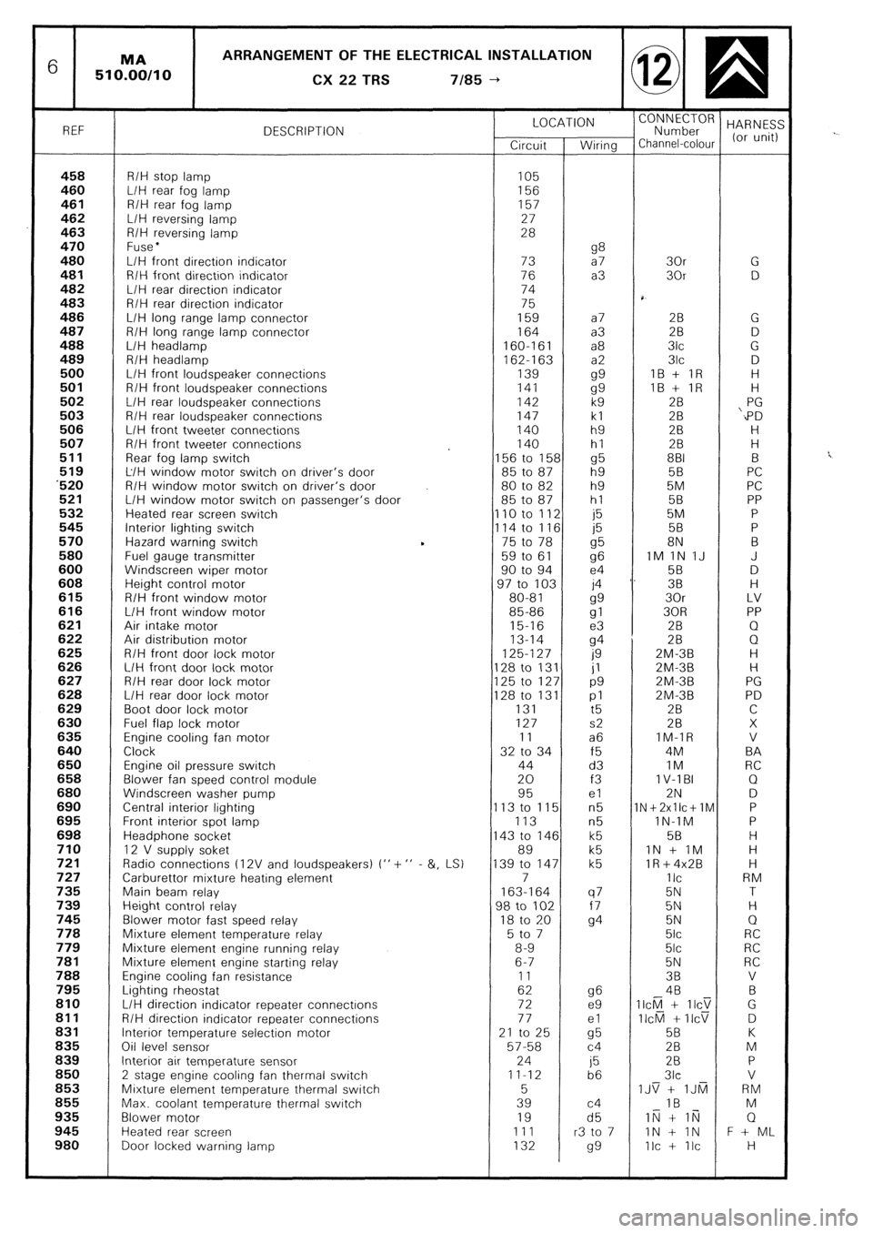
6 ARRANGEMENT OF THE ELECTRICAL INSTALLATION
CX
22 TRS 7185 --)
REF DESCRIPTION LOCATION
“;;;;;roR HARNES:
Circuit Wiring Channel-colour (or unit)
458 R/H stop lamp 105 460 L/H rear fog lamp 156 461 R/H rear fog lamp 157
462 L/H reversing lamp 27
463 R/H reversing lamp 28
470 Fuse l 480 g8 L/H front direction indicator 73 a7 30r G 481 R/H front direction indicator 76 a3 30r D 482 L/H rear direction indicator 74
483 R/H rear direction indicator 75
486 L/H long range lamp connector 159 a7 28 G 487 R/H long range lamp connector 164 a3 2B D 488 L/H headlamp 160-161 a8 3lc G
489 R/H headlamp
162-l 63 a2 3lc D 500 L/H front loudspeaker connections 139
gg IB + IR H 501 R/H front loudspeaker connections 141
gg IB + IR H 502 L/H rear loudspeaker connections 142 k9 28 PG 503 R/H rear loudspeaker connections 147 kl 28 ‘,PD 506 L/H front tweeter connections 140 h9 2B H 507 R/H front tweeter connections 140 hl 28 H
511 Rear fog lamp switch 156 to 158 g5 881 B 519 L/H window motor switch on driver’s door 85 to 87 h9 5B PC ‘520 R/H window motor switch on driver’s door 80 to 82 h9 5M PC 521 L/H window motor switch on passenger’s door 85 to 87 hl 58 PP 532 Heated rear screen switch 110 to 112 j5 5M P 545 Interior lighting switch
114 to 116 j5 58 P 570 Hazard warning switch 75 to 78
g5 8N B 580 Fuel gauge transmitter 59 to 61
96 IM 1N IJ J 600 Windscreen wiper motor 90 to 94 e4 58 D 608 Height control motor 97 to 103 j4 ‘. 38 H 615 R/H front window motor 80-81
gg 30r LV 616 L/H front window motor 85-86
gl 30R PP 621 Air intake motor 15-16 e3 2B Q 622 Air distribution motor 13-14
94 28 0 625 R/H front door lock motor 125-127
0 ZM-3B H 626 L/H front door lock motor 128 to 131 jl ZM-3B H 627 R/H rear door lock motor 125 to 127 p9 2M-3B PG 628 L/H rear door lock motor 128 to 131 pl 2M-3B PD 629 Boot door lock motor 131
t5 2B C 630 Fuel flap lock motor 127 s2 28 X 635 Engine cooling fan motor 11 a6 IM-IR V 640 Clock 32 to 34 f5 4M BA 650 Engine oil pressure switch 44 d3 IM RC 658 Blower fan speed control module 20 f3 1 V-l BI Q 680 Windscreen washer pump 95 el 2N D 690 Central interior lighting 113 to 115 n5 1N+2xllc+lM P 695 Front interior spot lamp 113 n5 lN-1M P 698 Headphone socket 143 to 146 k5 58 H 710 12 V supply soket 89 k5 IN + IM H 721 Radio connections t 12V and loudspeakers) I” + ” - &, LS) 139 to 147 k5 lR+4x2B H 727 Carburettor mixture heating element 7 IIC RM 735 Main beam relay 163-164 q7 5N T 739 Height control relay 98 to 102 f7 5N H 745 Blower motor fast speed relay 18 to 20
94 5N Q 778 Mixture element temperature relay 5 to 7 5lc RC 779 Mixture element engine running relay 8-9 5lc RC 781 Mixture element engine starting relay 6-7 5N RC 788 Engine cooling fan resistance 11 38 V 795 Lighting rheostat 62 g6 4B B 810 L/H direction indicator repeater connectrons 72 e9 II&l + IICT G 811 R/H direction indicator repeater connections 77 el II&l + IICV D 831 Interior temperature selection motor 21 to 25
cl5 5B K 836 Oil level sensor 57-58 c4 28 M 839 Interior air temperature sensor 24
j5 28 P 850
2 stage engine cooling fan thermal switch 11-12
b6 3lc V 853 Mixture element temperature thermal switch 5 IJS + IJti RM 855 Max. coolant temperature thermal switch 39 c4 IB M 935 Blower motor 19 d5 IN + li;j Q 945 Heated rear screen 111 r3 to 7 IN + IN F + ML 980 Door locked warning lamp 132
99 Ilc + Ilc H
Page 399 of 648
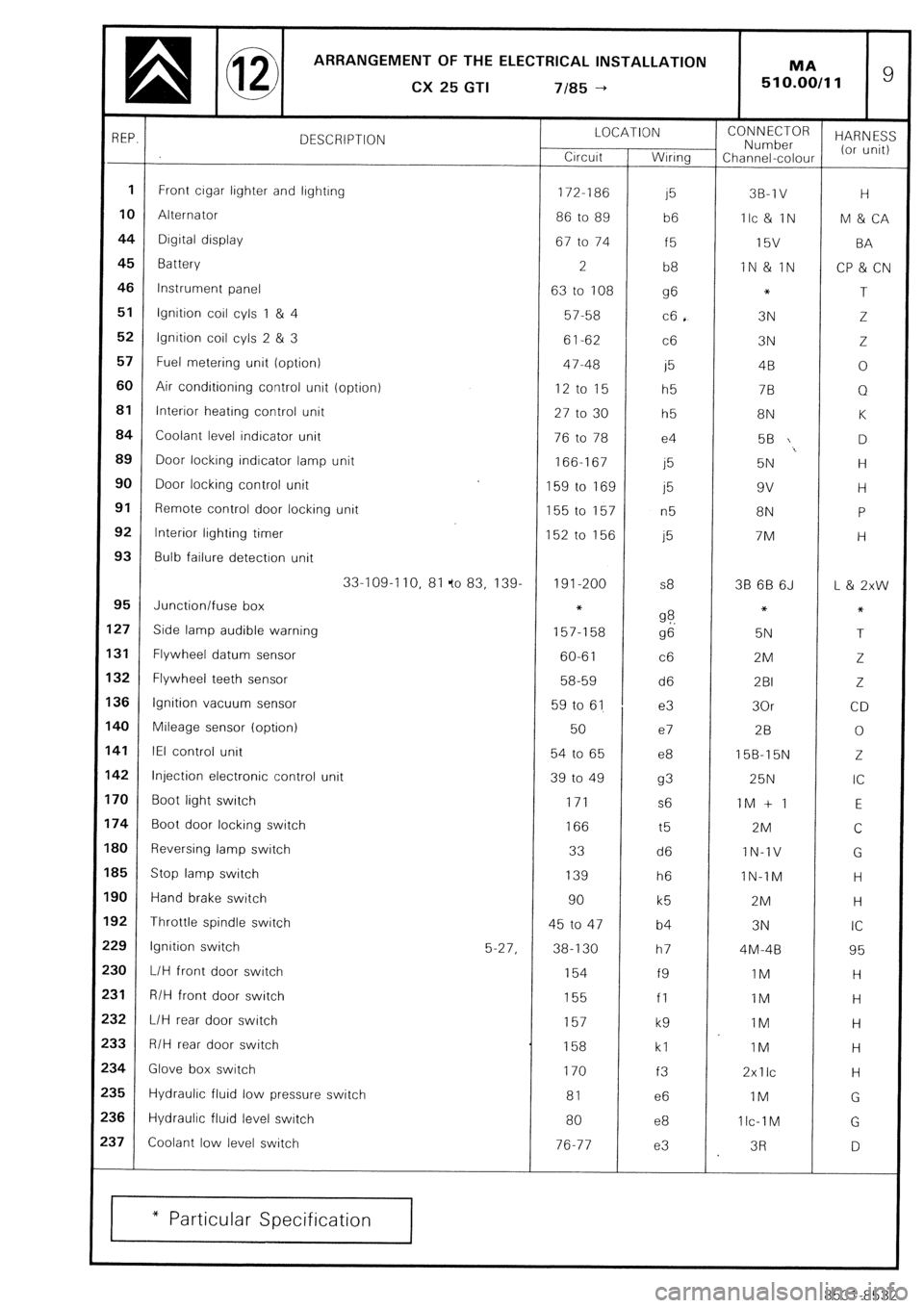
ARRANGEMENT OF THE ELECTRICAL INSTALLATION
a @ CX25GTI 7185-t MA ’ 510.00/11
REP.
DESCRIPTION LOCATION
Crrcurt Wrnng CONNECTOR
Number HARN ES:
Channel-colour (or unit)
1 Front lighter and lrghtrng
crgar 172-186 15 3B-1 V H
10 Alternator
86 to 89
b6 Ilc & IN M & CA
44 Dtgital display
67 to 74 f5 l5V BA
45
Battery
2
b8 IN & IN
CP & CN
46 Instrument panel
63 to 108 g6 *
T
51 Ignition coil cyls 1 & 4
57-58 c6 . 3N Z
52 lgnrtion coil cyls 2 & 3
61-62 c6 3N Z
57 Fuel metering unit (option)
47-48 i5 4B 0
60 Air conditioning control unit (option)
12 to 15
h5 7B Q
81 Interior heating control unit
27 to 30 h5 8N K
84 Coolant level indicator unit
76 to 78 e4 56 D
89
Door locking indicator lamp unit
166-167
j5 5N H
90 Door locking control unit
159 to 169 j5 9v H
91
Remote control door locking unit
155 to 157
n5 8N P
92 Interior lighting timer
152 to 156 j5 7M H
93 Bulb failure detectron unit
33-109-I 10, 81 fo 83, 139. 191-200 s8 38 6B 6J L & 2xw
95 Junction/fuse box *
27 Side lamp audible warning 9 ?. *
*
157-l 58
g6 5N T
31
Flywheel datum sensor
60-61 c6 2M
Z
32 Flywheel teeth sensor
58-59 d6 2BI 2.
36 Ignition vacuum sensor
59 to 61 e3 30r CD
40 Mileage sensor (option)
50 e7 28 0
41 IEI control unit
54 to 65 e8 15B-15N Z
42 Injection electronic control unit
39 to 49 93 25N IC
70 Boot light switch
171 s6 1M + 1 E
74
Boot door locking switch
166 t5 2M
C
BO
Reversing lamp switch 33
d6 IN-1V
G
B5 Stop lamp switch
139 h6 IN-TM H
90 Hand brake switch
90
k5 2M H
92 Throttle spindle switch
45 to 47 b4 3N IC
29 lgnrtion switch
5-27, 38-130 h7 4M-48 95
30
L/H front door switch 154
f9 IM H
31 R/H front door switch
155
fl IM H
32 L/H rear door switch
157
k9 IM H
33 R/H rear door switch
158 kl 1M H
34
Glove box switch
170
f3 2xllc
H
35 Hydraulic fluid low pressure switch
81 e6 IM
G
$6
Hydraulic fluid level swatch
80 e8 1 Ic-1 M
G
$7
Coolant low level switch
76-77 e3 3R
D
* Particular Specification
8531-8532
Page 400 of 648
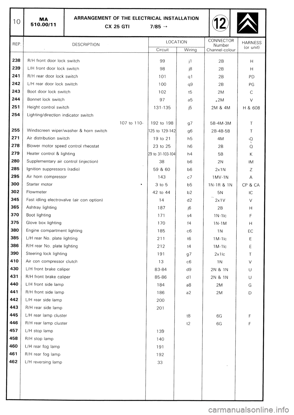
10 MA ARRANGEMENT OF THE ELECTRICAL INSTALLATION
510.00/11
CX
25 GTI 7185 -+
REP. DESCRIPTION LOCATION CONNECTOR
Number HARNESS
Crrcuit Wiring Channel-colour (or unrt)
238 R/H front door lock switch 99
JI 2B H
239
L/H front door lock switch 98
j8 2B H
241 R/H rear door lock switch 101
ql 28 PD
242 L/H rear door lock switch 100
99 28 PG
243 Boot door lock switch 102 t5 2M C
244 Bonnet lock switch 97 a5 ,2M v
251 Height control switch 131-135
j5 2M & 4M H & 608
254 Lighting/direction indicator switch
107 to IIO- 192 to 198
97 5B-4M-3M T
255 Windscreen wiper/washer & horn switch 125 to 129-142
96 2B-4B-5B T
271 Air distribution switch 19 to 21 h5 4M \Q
278 Blower motor speed control rheostat 23 to 25 h6 2B ;1
279 Heater control & lighting
29 to 31-103-104 h4 58 K
280 Supplementary air control (injection) 38 b6 2N IM
285 Ignition suppressors (radio) 59 & 60 b6 2xlN 2
295
Air horn compressor 143
c7 IMV-IN A
300
Starter motor t
3 to 5 b5 IN-IR & IN CP & CA
302 Flowmeter 42 to 44 b2 5N IC
545 Fast idling electrovalve (air con option) 14 d2 *. 2xlV V
$65 Ashtray lighting 187 1’3 2B H
$70 Boot lighting 171 s4 IN-TIC F
i75 Glove box lighting 170 f4 lN-IM H
I80 Engine compartment lighting 185 c6 IN EC
385 L/H rear No. plate lighting 211 t6 IM-llc E
386 R/H rear No. plate lighting 212 t4 IM-llc
E
390 Steering lock lighting 191
97 2xllc T
$10 Air con compressor clutch 13
c6 IN V
$30 L/H front brake caliper 83-84 d9 2N& IN U
$31 R/H front brake caliper 85-86 dl 2N& IN U
140 L/H front side lamp 184 a8 2M G
F41 R/H front side lamp 186 a2 2M D
L42 L/H rear side lamp 200
c43
R/H rear side lamp 201
145
L/H rear lamp cluster t8 6G F
C46 R/H rear lamp cluster t2 6G F
L57 L/H stop lamp 139
158 R/H stop lamp 140
160
L/H rear fog lamp 191
1-61 R/H rear fog lamp 192
.62 L/H reversing lamp 33