set clock CITROEN CX 1988 Service Manual
[x] Cancel search | Manufacturer: CITROEN, Model Year: 1988, Model line: CX, Model: CITROEN CX 1988Pages: 648, PDF Size: 95.8 MB
Page 113 of 648

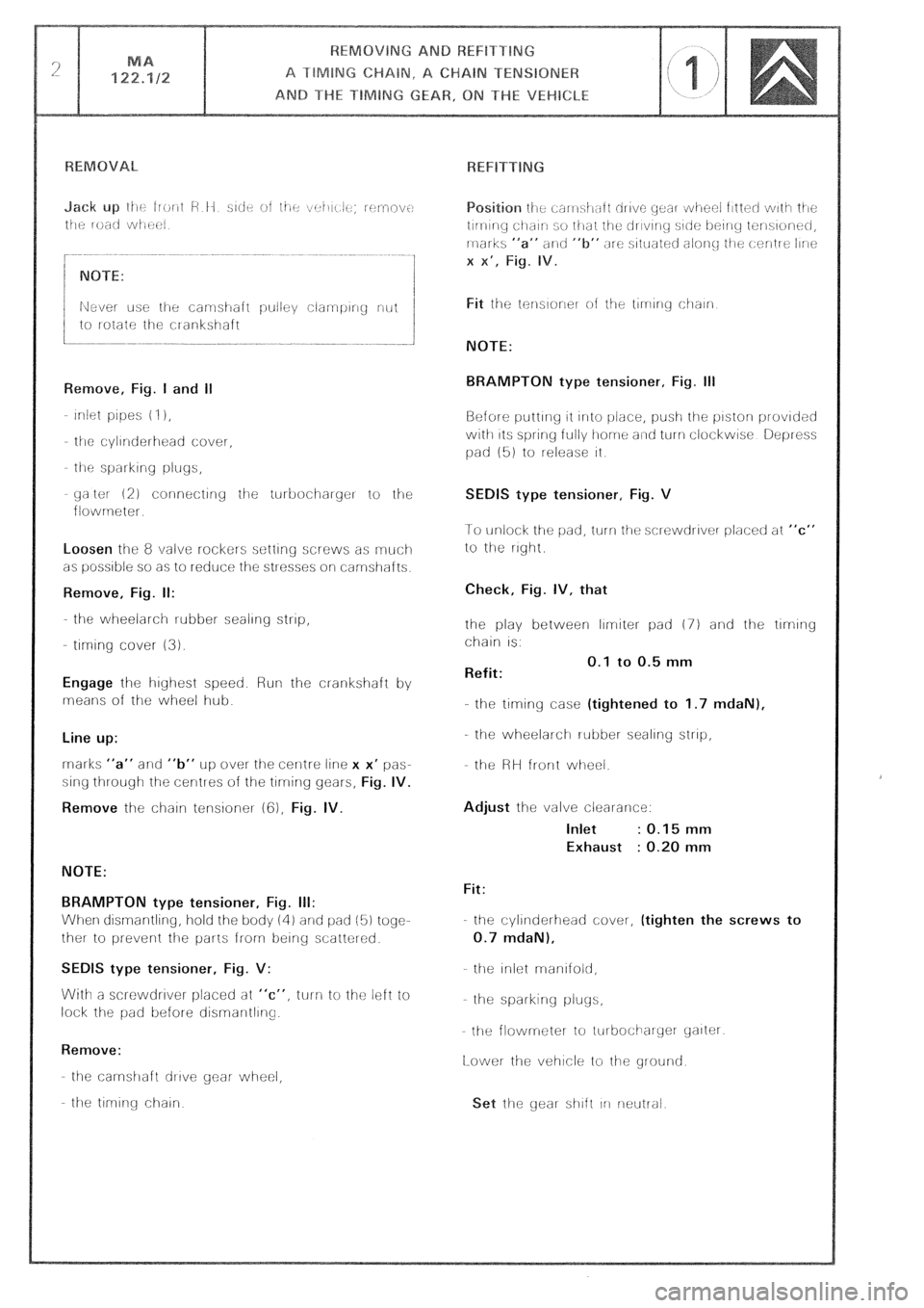
yaltot 12) connectiriy iije turbocihaiger to the
flowrneter.
Loosen the 8 valve rockers setting screws as rnuci-1
as possible so as to reduce the stresses oli camshafts
Remove, Fig. II:
the wheelarch rubber sealing strip,
- tlrmng cover (3).
Engage lhe highest speed. Run the cl-ankshaft by
means of the wheel hub.
Line up:
rnarks “a” and “b” UP over the cenlre line x x’ pas-
sing through the centres of the tlrrring gears,
Fig. IV.
Remove
the chain tensioner (cj), Fig. IV.
NOTE:
BRAMPTON type tensioner, Fig. III:
When dismantling, hold the body iii) and pad (5) togc-
ther to prevent the parts from being scatter&
SEDlS type tensioner, Fig. V:
With a screwdrlver placed at “c”, turn to the left io
lock the pad before disrnarltllrlg.
Remove:
the carnshaft drive gear- wheel,
the tlrnlr-ig chain
NOTE:
BRAMPTON type tensioner, Fig. Ill
Before putting 11 irrlo i.)ir!ce, push the pistorl provided
with 11s spring fully home a~rtl turn clockwise Depress
pad (51 to release it
SEDIS type tensioner, Fig. V
1-o unlock the pad, turn tile sclewdrlver placed at “c”
to the right
Check, Fig. IV, that
the play between limiter pad (7) and the tlmng
chain IS.
Refit: 0.1 to 0.5 mm
-.
the timing case (tightened to 1.7 mdaN),
the wheelarch rubber sealing strip,
the HH front wheel.
Adjust the valve clearance:
Inlet : 0.15 mm
Exhaust : 0.20 mm
Fit:
the cylinderhead cover, (tighten the screws to
0.7 mdaN),
the Iniot rnanlfold,
he spai-king pluys,
the flowmeter to iurbocilarycr yalter
[Lower the vehicle to the ground
Page 216 of 648

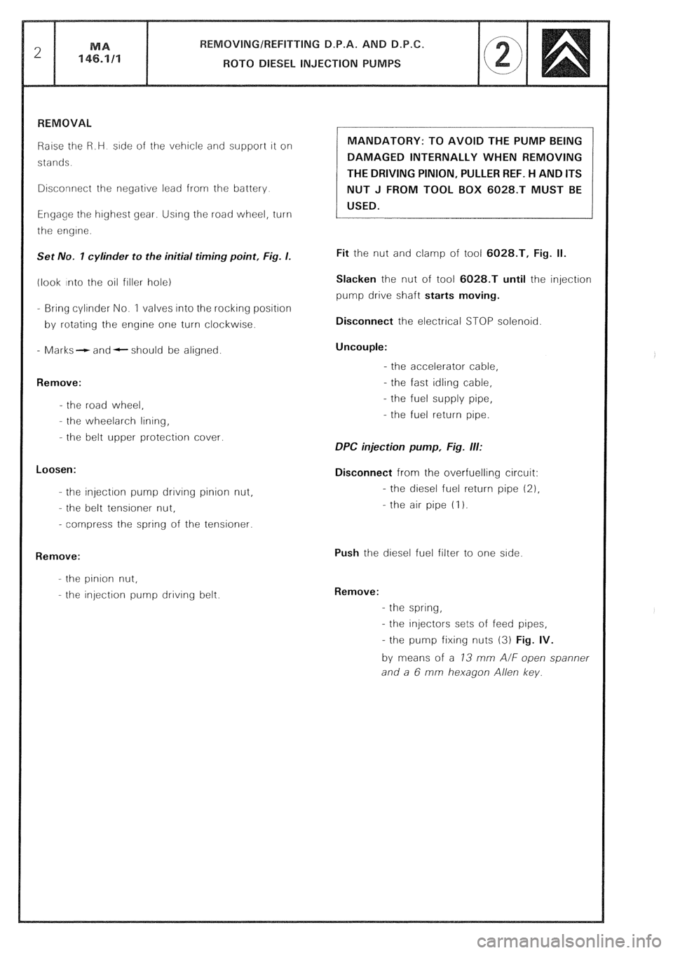
Raise the R.H side of the vehicle and support it on
stands.
Disconnect the negative lead from the battery
Engage the highest gear. Using the road wheel, turn
the engine.
Set No. I cylinder to the initial timing point, Fig. I.
(look into the oil filler hole)
- Bring cylinder No. 1 valves into the rocking position
by rotating the engine one turn clockwise.
- Marks- and- should be aligned.
Remove:
- the road wheel,
- the wheelarch lining,
- the belt upper protection cover.
Loosen:
- the injection pump drrvrng pinion nut,
- the belt tensioner nut,
- compress the spring of the tensioner.
Remove:
- the pinion nut,
- the injection pump driving belt. MANDATORY: TO AVOID THE PUMP BEING
DAMAGED INTERNALLY WHEN REMOVING
THE DRIVING PINION, PULLER REF. H AND ITS
NUT J FROM TOOL BOX 6028.T MUST BE
USED.
Fit the nut and clamp of tool 6028.T, Fig. II.
Slacken the nut of tool 6028.T until the injection
pump drive shaft starts moving.
Disconnect the electrical STOP solenoid
Uncouple:
- the accelerator cable,
- the fast idling cable,
- the fuel supply pipe,
- the fuel return pipe.
DPC injection pump, Fig. ill:
Disconnect from the overfuelling circuit:
- the diesel fuel return pipe (21,
- the air pipe (I 1.
Push the diesel fuel filter to one side
Remove:
- the spring,
- the injectors sets of feed pipes,
- the pump fixing nuts (3) Fig. IV.
by means of a 73 mm A/F open spanner
and a 6 mm hexagon Allen key.