boot CITROEN DS3 2018 Handbook (in English)
[x] Cancel search | Manufacturer: CITROEN, Model Year: 2018, Model line: DS3, Model: CITROEN DS3 2018Pages: 248, PDF Size: 8.79 MB
Page 164 of 248

162
F After emptying the bottle or container, wipe away any spillage around the tank filler
using a
damp cloth.
If any AdBlue
® additive is spilt or splashed,
wash immediately with cold water or wipe
with a
damp cloth.
If the AdBlue
® has crystallised, clean it off
using a
sponge and hot water.
F
R
efit the blue cap to the tank filler and turn it
a
6
th of a turn clockwise, to its stop.
F
D
epending on equipment, return the spare
wheel and/or the storage box to the bottom
of the boot.
F
R
efit the boot carpet and close the tailgate.
Important: when topping up after
running out of AdBlue
®, you must wait
for around 5 minutes before switching
on the ignition, without opening the
driver's door , or unlocking the vehicle ,
or placing the key in the ignition
switch .
Switch on the ignition, then after
10
seconds, start the engine.
Advice on care and
maintenance
Recommendations on the care and
maintenance of your vehicle are given in the
Maintenance and Warranty Guide.
Textured paint
Textured paint reacts to light with variations of
appearance and finish that emphasise the car's
lines and form. This paint coating has particles
that remain visible and create a unique satin
relief effect. Its lightly granulated texture gives
it a
surprising feel. Observe the following recommendations
to avoid damaging the paint finish:
-
c
hoose a high pressure wash, or at
least a high water delivery; roller brush
washing is compatible.
-
g
ently wipe the body with a clean
microfibre cloth.
-
c
arefully wipe off any fuel spilt on the
body using a soft cloth, then allow to
d r y.
-
c
lean off minor marks (for example,
finger marks), using the product in the
"TECHNATURE" range intended for
removing insects.
H o w eve r,
-
d
o not select the programme with hot
wax finish.
-
d
o not use waterless cleaning.
-
n
ever polish the vehicle.
-
d
o not use paint restorers, abrasive
or polishing products, or bright paint
preser vers (wax polish, for example).
It is always preferable to have paint
repairs carried out in the dealer network or
by a
qualified workshop.
07
Practical information
Page 168 of 248

166
Access to the kit
This kit is installed in the under floor storage,
under the boot floor.
Composition of the kit
1.12 V compressor, with built-in pressure
gauge.
2. Bottle of sealant, with built-in hose.
3. Speed limit sticker.
Repair procedure
F Park the vehicle without obstructing any
traffic and apply the parking brake.
F
F
ollow the safety instructions (hazard
warning lamps, warning triangle, wearing
high visibility vest, etc.) according to the
legislation in force in the country where you
are driving.
F
S
witch off the ignition.
F
U
ncoil the pipe stowed under the
compressor.
Avoid removing any foreign bodies which
have penetrated the tyre. F
R
emove the valve cap from the tyre to be
repaired and keep it in a
clean place.
F
C
onnect the pipe from the compressor to
the bottle of sealant. F
T
urn over the sealant bottle and secure it in
the cut-out provided on the compressor.
F
C
onnect the hose from the bottle of sealant
to the valve of the tyre to be repaired and
tighten firmly.
08
In the event of a breakdown
Page 171 of 248

169
If a pressure of 2 bars is not reached after
7 minutes, this indicates that the tyre is
not repairable; contact your dealer or
a
qualified workshop for recovery.
F
O
nce the correct pressure is reached, put
the switch to the " O" position.
F
R
emove the kit then stow it.
Do not drive more than 120
miles (200 km)
with a
temporarily repaired tyre; see your
dealer or a
qualified workshop to change
the tyre.
Should the pressure of one or more tyres
be adjusted, it is necessary to reinitialise
the under-inflation detection system.
For more information on Under-inflation
detection , refer to the corresponding
section.
Spare wheel
Scan the QR code on page 3 to view
e xplanatory videos.
Procedure for changing a
damaged wheel with
the spare wheel using the tools provided with
the vehicle.
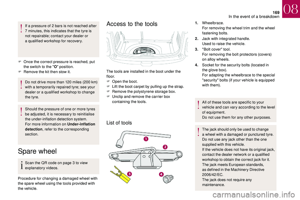
Access to the tools
List of tools
1. Wheelbrace.
For removing the wheel trim and the wheel
fastening bolts.
2. Jack with integrated handle.
Used to raise the vehicle.
3. "Bolt cover" tool.
For removing the bolt protectors (covers)
on alloy wheels.
4. Socket for the security bolts (located in
the glove box).
For adapting the wheelbrace to the special
"security" bolts (if your vehicle is equipped
with them).
All of these tools are specific to your
vehicle and can vary according to the level
of equipment.
Do not use them for any other purposes.
The jack should only be used to change
a
wheel with a damaged or punctured tyre.
Do not use any jack other than the one
supplied with this vehicle.
If the vehicle does not have its original jack,
contact the dealer network or a
qualified
workshop to obtain the correct jack for it.
The jack meets European standards,
as defined in the Machinery Directive
2006/42/EC.
The jack does not require any
maintenance.
The tools are installed in the boot under the
f l o o r.
F
O
pen the boot.
F
L
ift the boot carpet by pulling up the strap.
F
R
emove the polystyrene storage box.
F
U
nclip and remove the carrier box
containing the tools.
08
In the event of a breakdown
Page 172 of 248

170
Access to the spare wheel
Taking out the wheelPutting the wheel back in place
The spare wheel is located in the boot under
t h e f l o o r.
Depending on the country of sale, you will
have a "space-saver" type spare wheel or
a
temporary puncture repair kit.
F
U
nscrew the central nut.
F
R
emove the fastening device (nut and bolt). F
R
aise the spare wheel towards you from the
r e a r.
F
T
ake the wheel out of the boot.
On vehicles with a "space-saver" type
spare wheel, the punctured tyre can
replace the "space-saver" wheel; however,
the boot floor will no longer be even.
F
P
ut the wheel back in its housing.
F
S
lacken the nut on the bolt by a few turns.
F
P
osition the fastening device (nut and bolt)
in the middle of the wheel.
F
T
ighten fully until the central nut clicks, to
retain the wheel correctly. F
P
ut the carrier box back in place in the
centre of the wheel and clip it.
F
P
ut the polystyrene storage box back in
place.
F
R
eposition the carpet at the back of the boot
by folding it gently in two.
08
In the event of a breakdown
Page 174 of 248

172
On vehicles equipped with body sill
mouldings, the location of the jack
contact area is indicated by a mark on the
moulding. It is essential that the jack be
placed in line with this mark, in the jack
contact area, located behind the moulding
and not on the plastic moulding.
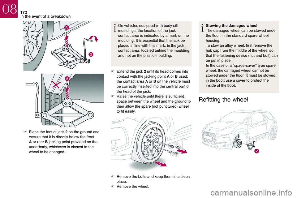
F
E
xtend the jack 2 until its head comes into
contact with the jacking point A or B used;
the contact area A or B on the vehicle must
be correctly inserted into the central part of
the head of the jack.
F
Ra
ise the vehicle until there is sufficient
space between the wheel and the ground to
then allow the spare (not punctured) wheel
to fit easily. Stowing the damaged wheel
The damaged wheel can be stowed under
the floor, in the standard spare wheel
housing.
To stow an alloy wheel, first remove the
hub cap from the middle of the wheel so
that the fastening device (nut and bolt) can
be put in place.
In the case of a "space-saver" type spare
wheel, the damaged wheel cannot be
stowed under the floor. It must be stowed
in the boot; use a
cover to protect the
inside of the boot.
Refitting the wheel
F Place the foot of jack 2 on the ground and
ensure that it is directly below the front
A or rear B jacking point provided on the
underbody, whichever is closest to the
wheel to be changed.
F
R
emove the bolts and keep them in a clean
place.
F
R
emove the wheel.
08
In the event of a breakdown
Page 179 of 248

177
3.LED side marker lamps.
4. Direction indicators (PY21W amber).
5. Foglamp (H21W red) or reversing lamp
(H21W ).
Amber or red colour bulbs, such as the
direction indicators or foglamps, must be
replaced by bulbs with identical colour and
specifications.
Access to bulbs
Removing the access cover
F Open the boot.
Ty p e 1 Ty p e 2Removing the lamp
To reassemble, proceed in reverse order.
Make sure to engage the lamp unit in its guides
while keeping it in line with the vehicle.
Refitting the access cover
Ty p e 1
F
R
emove the access cover by pulling it
downwards.
F
U
nscrew the lamp fixing wing nut.
F
U
nclip the lamp unit connector.
F
E
xtract the lamp unit carefully pulling it
straight towards the outside. F
P
osition the 3 hooks A of the cover in the
lower part.
08
In the event of a breakdown
Page 180 of 248

178
Ty p e 2
Changing bulbs
Model with conventional bulb lampsModel with rear 3D lamps
Direction indicators (4) and foglamp or
reversing lamp (5)
Replacing LED sidelamps and brake
lamps (diodes)
For the replacement of this type of diode
lamp, contact the dealer network or a
qualified
workshop.
F
T
ip the cover upwards and position the
hooks B under the boot trim.
F
Ra
ise the cover.
F
S
lide the cover so as to put it properly back
in place. F
P
osition the cover in the lower part.
F
T
ip the cover upwards.
F
T
urn the bulb a quarter of a turn and change
it.
F
S
pread the four tabs and remove the bulb
h o l d e r.
F
T
urn the bulb a
quarter turn and change it.
08
In the event of a breakdown
Page 181 of 248

179
Number plate lamps (LED)
Third brake lamp (4 x W5W bulbs)F Push centrally on the lamp body, while levering it with two screwdrivers to extract it
to the outside.
F
D
isconnect the connector and, if necessary,
the lamp screenwash tube.
F
T
urn the bulb holder corresponding to the
faulty bulb a
quarter turn.
F
P
ull the bulb out and change it.
To refit, carry out these operations in reverse
o r d e r.Third brake lamp (LED)
For the replacement of this type of LED lamp,
contact the dealer network or a qualified
workshop.
F
O
pen the boot.
F
R
emove the two blanking plugs A located
on the lining. For the replacement of this type of light emitting
diode lamp, contact the dealer network or
a
qualified workshop.
08
In the event of a breakdown
Page 182 of 248

180
Interior lighting
Courtesy lamp (1/W5W)
Unclip the cover of courtesy lamp 1 with a fine
s crewdriver, on the control side, to access the
faulty bulb.
Map reading lamps (2/W5W)
Unclip the cover of courtesy lamp 1 . To
access the faulty bulb, unclip the reading lamp
2
partition concerned.
Boot lamp (W5W) Footwell and central storage lighting
(W5W)
Unclip the unit to access the bulb.
Glove box lighting (W5W)Unclip the unit by pushing the base from
behind.
Unclip the unit to access the bulb.
08
In the event of a breakdown
Page 186 of 248

184
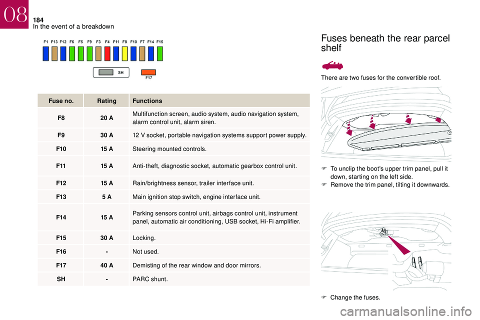
There are two fuses for the convertible roof.F
T
o unclip the boot's upper trim panel, pull it
down, starting on the left side.
F
R
emove the trim panel, tilting it downwards.
Fuse no.
Rating Functions
F8 20
A Multifunction screen, audio system, audio navigation system,
alarm control unit, alarm siren.
F9 30
A 12
V socket, portable navigation systems support power supply.
F10 15
A Steering mounted controls.
F11 15
A Anti-theft, diagnostic socket, automatic gearbox control unit.
F12 15
A Rain/brightness sensor, trailer interface unit.
F13 5
A Main ignition stop switch, engine interface unit.
F14 15
A Parking sensors control unit, airbags control unit, instrument
panel, automatic air conditioning, USB socket, Hi-Fi amplifier.
F15 30
A Locking.
F16 -Not used.
F17 40
A Demisting of the rear window and door mirrors.
SH -PARC shunt.
Fuses beneath the rear parcel
shelf
F Change the fuses.
08
In the event of a breakdown