replacement CITROEN DS3 2018 Handbook (in English)
[x] Cancel search | Manufacturer: CITROEN, Model Year: 2018, Model line: DS3, Model: CITROEN DS3 2018Pages: 248, PDF Size: 8.79 MB
Page 46 of 248

44
With the remote control
F Press the closed padlock to lock the vehicle completely.
F
P
ress the closed padlock again within five
seconds to deadlock the vehicle.
With the key
F Turn the key to the rear in the driver's door lock to lock the vehicle completely.
F
T
urn the key to the rear again within five
seconds to deadlock the vehicle.
Deadlocking is confirmed by fixed illumination
of the direction indicators for approximately two
seconds.
Depending on your version, the door mirrors
fold at the same time.
Locating your vehicle
F Press the closed padlock to locate your locked vehicle in
a
car park.
This is indicated by lighting of the courtesy
lamps and flashing of the direction indicators
for a
few seconds.
Remote control problem
Following disconnection of the vehicle battery,
replacement of the remote control battery or
in the event of a remote control malfunction,
you can no longer unlock, lock or locate your
vehicle.
F
F
irst of all, use the key in the door lock to
unlock or lock your vehicle.
F
T
hen reinitialise the remote control.
If the problem persists, contact the dealer
network as soon as possible.
Reinitialisation
Battery type: CR1620/3 volts.
F
S
witch off the ignition.
F
T
urn the key to position 2
(Ignition) .
F
P
ress the closed padlock button for a
few
seconds.
F
S
witch off the ignition and remove the key
from the switch.
The remote control is now fully operational
again.
Changing the battery
If the battery is discharged, you are
informed by lighting of this warning lamp in
the instrument panel, an audible signal and
a
message in the multifunction screen.
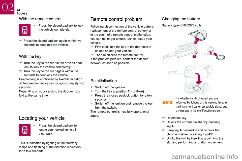
F Unfold the key.
F U nlock the chrome finisher by pressing
lug A .
F
K
eep lug A pressed in and remove the
chrome finisher by sliding it at 45°.
F
U
nclip the unit by inserting a coin into the
slot and per forming a
rotation movement.
02
Access
Page 159 of 248

157
The cooling fan may star t after
switching off the engine: take care
with articles and clothing that might be
caught by the fan blades.
Fluid specification
The fluid must conform to the manufacturer's
recommendations.
Screenwash fluid level
Top up to the required level when
necessary.
Fluid specification
The screenwash fluid must be topped up with
a ready for use mix.
In winter (temperatures below zero), a fluid with
antifreeze must be used that is appropriate for
the prevailing conditions, in order to preser ve
the elements of the system (pump, tank, ducts,
e t c .) . To avoid the risk of scalding when you need to
top up in an emergency, place a cloth around
the cap and unscrew the cap by two turns to
allow the pressure to drop.
Once the pressure has dropped, remove the
cap and top up the level.
Diesel fuel additive level
(Diesel with particle filter)
The additive tank minimum level is
indicated by fixed illumination of this
warning lamp, accompanied by an
audible signal and a
message that
the particle filter additive level is
too low.
Topping up
This additive must be topped up without
delay by a member of the dealer network or
a
qualified workshop.
AdBlue level
An alert is triggered once the reser ve level is
reached.
To avoid the vehicle being immobilised as per
regulations, you must top up with AdBlue.
For more information on AdBlue
® and the SCR
system, and in particular topping it up, refer to
the corresponding section.
Checks
Unless otherwise indicated, check these
components in accordance with the
manufacturer's service schedule and according
to your engine.
Otherwise, have them checked by the dealer
network or a
qualified workshop.
12 V battery
The battery does not require any
maintenance.
However, check regularly that the
terminals are correctly tightened and
that the connections are clean.
Versions equipped with Stop & Start are
fitted with a
12 V lead-acid battery of
specific technology and specification.
Its replacement should be carried out
only in the dealer network or a
qualified
workshop.
When carrying out any operation on the 12
V
battery, refer to the corresponding section for
details of the precautions to be taken before
starting work.
Filling with pure water is prohibited under all
circumstances (risk of freezing, limestone
deposits, etc.).
07
Practical information
Page 177 of 248

175
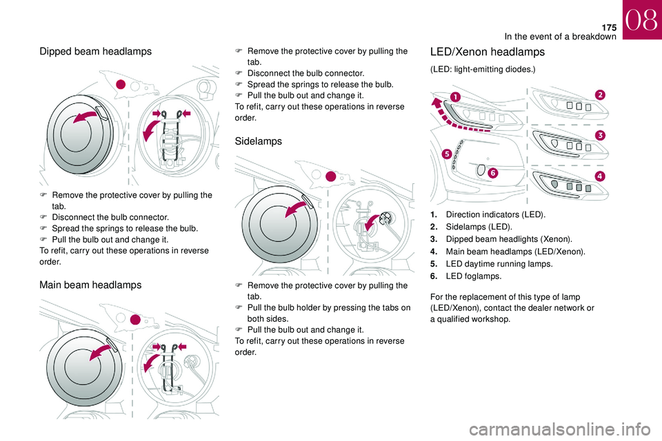
Dipped beam headlamps
Main beam headlampsF Remove the protective cover by pulling the tab.
F
D
isconnect the bulb connector.
F
S
pread the springs to release the bulb.
F
P
ull the bulb out and change it.
To refit, carry out these operations in reverse
o r d e r.
Sidelamps
F Remove the protective cover by pulling the tab.
F
D
isconnect the bulb connector.
F
S
pread the springs to release the bulb.
F
P
ull the bulb out and change it.
To refit, carry out these operations in reverse
o r d e r.
F
R
emove the protective cover by pulling the
tab.
F
P
ull the bulb holder by pressing the tabs on
both sides.
F
P
ull the bulb out and change it.
To refit, carry out these operations in reverse
o r d e r.
LED/Xenon headlamps
(LED: light-emitting diodes.)
1. Direction indicators (LED).
2. Sidelamps (LED).
3. Dipped beam headlights (Xenon).
4. Main beam headlamps (LED/Xenon).
5. LED daytime running lamps.
6. LED foglamps.
For the replacement of this type of lamp
(LED/Xenon), contact the dealer network or
a
qualified workshop.
08
In the event of a breakdown
Page 178 of 248

176
Integrated direction indicator side
repeaters
Contact the dealer network or a qualified
w orkshop to obtain the module.
LED foglamps
LED daytime running lampsRear lamps
Model with conventional bulb lamps
1. Brake/sidelamps (P21/5W).
2. Sidelamps (P5W).
3. Direction indicators (PY21W amber).
4. Foglamp (PR21W red) or reversing lamp
(P21W ).
Model with rear 3D lamps
F Insert a screwdriver towards the centre of
the repeater between the repeater and the
base of the mirror.
F
L
ever with the screwdriver to extract the
repeater and pull it out.
F
D
isconnect the connector from the repeater.
F
R
eplace the module.
To refit, carry out these operations in reverse
o r d e r. For the replacement of this type of diode
lamp, contact the dealer network or a
qualified
workshop.
For the replacement of this type of diode
lamp, contact the dealer network or a
qualified
workshop. 1.
3D LED sidelamps.
2. LED brake/sidelamps.
08
In the event of a breakdown
Page 180 of 248

178
Ty p e 2
Changing bulbs
Model with conventional bulb lampsModel with rear 3D lamps
Direction indicators (4) and foglamp or
reversing lamp (5)
Replacing LED sidelamps and brake
lamps (diodes)
For the replacement of this type of diode
lamp, contact the dealer network or a
qualified
workshop.
F
T
ip the cover upwards and position the
hooks B under the boot trim.
F
Ra
ise the cover.
F
S
lide the cover so as to put it properly back
in place. F
P
osition the cover in the lower part.
F
T
ip the cover upwards.
F
T
urn the bulb a quarter of a turn and change
it.
F
S
pread the four tabs and remove the bulb
h o l d e r.
F
T
urn the bulb a
quarter turn and change it.
08
In the event of a breakdown
Page 181 of 248

179
Number plate lamps (LED)
Third brake lamp (4 x W5W bulbs)F Push centrally on the lamp body, while levering it with two screwdrivers to extract it
to the outside.
F
D
isconnect the connector and, if necessary,
the lamp screenwash tube.
F
T
urn the bulb holder corresponding to the
faulty bulb a
quarter turn.
F
P
ull the bulb out and change it.
To refit, carry out these operations in reverse
o r d e r.Third brake lamp (LED)
For the replacement of this type of LED lamp,
contact the dealer network or a qualified
workshop.
F
O
pen the boot.
F
R
emove the two blanking plugs A located
on the lining. For the replacement of this type of light emitting
diode lamp, contact the dealer network or
a
qualified workshop.
08
In the event of a breakdown
Page 183 of 248

181
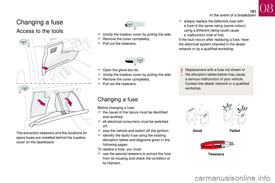
Changing a fuse
Access to the tools
The extraction tweezers and the locations for
spare fuses are installed behind the fusebox
cover on the dashboard.
Changing a fuse
F always replace the defective fuse with
a fuse of the same rating (same colour);
using a
different rating could cause
a
malfunction (risk of fire).
If the fault recurs after replacing a
fuse, have
the electrical system checked in the dealer
network or by a
qualified workshop.
Replacement with a
fuse not shown in
the allocation tables below may cause
a
serious malfunction of your vehicle.
Contact the dealer network or a
qualified
workshop.
F
U
nclip the fusebox cover by pulling the side.
F
R
emove the cover completely,
F
P
ull out the tweezers.
F
O
pen the glove box lid.
F
U
nclip the fusebox cover by pulling the side.
F
R
emove the cover completely,
F
P
ull out the tweezers.
Before changing a
fuse:
F
t
he cause of the failure must be identified
and rectified,
F
a
ll electrical consumers must be switched
of f,
F
s
top the vehicle and switch off the ignition,
F
I
dentify the faulty fuse using the existing
allocation tables and diagrams given in the
following pages.
To replace a
fuse, you must:
F
u
se the special tweezers to extract the fuse
from its housing and check the condition of
its filament, Good
Failed
Tw e e z e r s
08
In the event of a breakdown