ignition CITROEN DS3 CABRIO 2018 Handbook (in English)
[x] Cancel search | Manufacturer: CITROEN, Model Year: 2018, Model line: DS3 CABRIO, Model: CITROEN DS3 CABRIO 2018Pages: 248, PDF Size: 8.79 MB
Page 167 of 248

165
Running out of fuel
(Diesel)
On vehicles fitted with Diesel engines, the fuel
system must be primed if you run out of fuel.For more information on Misfuel
prevention (Diesel) , refer to the
corresponding section.
If the engine does not start first time, do
not keep trying, but start the procedure
again from the beginning.
BlueHDi engines
F Fill the fuel tank with at least five litres of Diesel fuel.
F
S
witch on the ignition (without starting the
engine).
F
W
ait around 6 seconds and switch off the
ignition.
F
R
epeat the operation 10
times.
F
O
perate the starter to run the engine.
Other HDi engines
(except BlueHDi version)
F
F
ill the fuel tank with at least five litres of
Diesel.
F
O
pen the bonnet.
F
I
f necessary, unclip the cover to access the
priming pump.
F
O
perate the priming pump repeatedly until
resistance is felt (there may be resistance at
the first press).
F
O
perate the starter to start the engine (if the
engine does not start at the first attempt,
wait around 15
seconds before trying
again).
F
I
f the engine does not start after a few
attempts, operate the priming pump again
then start the engine.
F
P
ut the cover in place and clip it in.
F
C
lose the bonnet again.
Temporary puncture
repair kit
Scan the QR code on page 3 to view
e xplanatory videos.
Comprising a
compressor and a sealant
cartridge, it allows the temporary repair of
a
tyre so that you can drive to the nearest
garage.
It is designed to repair most punctures which
could affect the tyre, located on the tyre tread
or shoulder.
The vehicle's electrical system allows the
connection of the compressor for long
enough to inflate a
tyre after a puncture
repair.
Under-inflation detection
After repair of the tyre, the warning
lamp will remain on until the system is
reinitialised.
For more information on Under-inflation
detection , refer to the corresponding
section.
08
In the event of a breakdown
Page 168 of 248

166
Access to the kit
This kit is installed in the under floor storage,
under the boot floor.
Composition of the kit
1.12 V compressor, with built-in pressure
gauge.
2. Bottle of sealant, with built-in hose.
3. Speed limit sticker.
Repair procedure
F Park the vehicle without obstructing any
traffic and apply the parking brake.
F
F
ollow the safety instructions (hazard
warning lamps, warning triangle, wearing
high visibility vest, etc.) according to the
legislation in force in the country where you
are driving.
F
S
witch off the ignition.
F
U
ncoil the pipe stowed under the
compressor.
Avoid removing any foreign bodies which
have penetrated the tyre. F
R
emove the valve cap from the tyre to be
repaired and keep it in a
clean place.
F
C
onnect the pipe from the compressor to
the bottle of sealant. F
T
urn over the sealant bottle and secure it in
the cut-out provided on the compressor.
F
C
onnect the hose from the bottle of sealant
to the valve of the tyre to be repaired and
tighten firmly.
08
In the event of a breakdown
Page 169 of 248
167
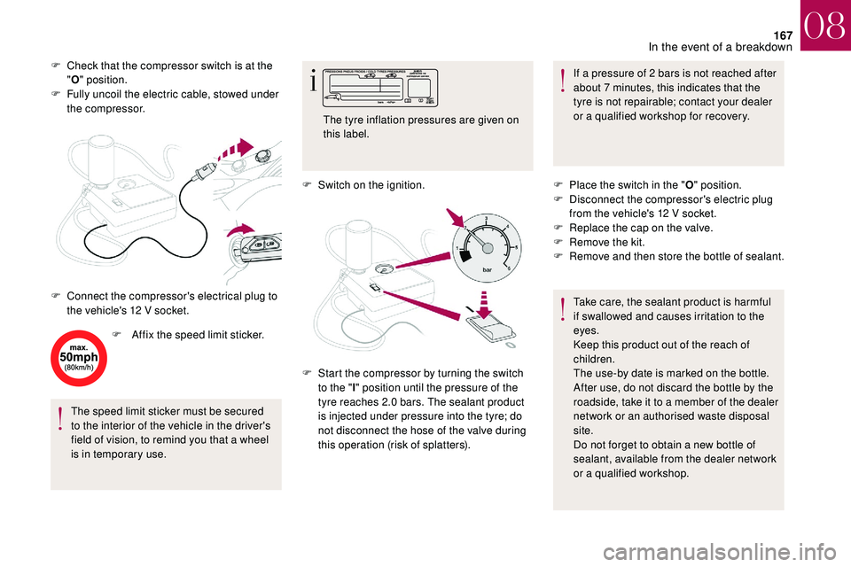
F Check that the compressor switch is at the "O " position.
F
F
ully uncoil the electric cable, stowed under
the compressor.
F
A
ffix the speed limit sticker.
The speed limit sticker must be secured
to the interior of the vehicle in the driver's
field of vision, to remind you that a
wheel
is in temporary use. F
S
witch on the ignition.If a
pressure of 2 bars is not reached after
about 7
minutes, this indicates that the
tyre is not repairable; contact your dealer
or a
qualified workshop for recovery.
F
C
onnect the compressor's electrical plug to
the vehicle's 12
V socket. The tyre inflation pressures are given on
this label.
F
S
tart the compressor by turning the switch
to the " l" position until the pressure of the
tyre reaches 2.0
bars. The sealant product
is injected under pressure into the tyre; do
not disconnect the hose of the valve during
this operation (risk of splatters). F
P
lace the switch in the "O" position.
F
D
isconnect the compressor's electric plug
from the vehicle's 12
V socket.
F
R
eplace the cap on the valve.
F
R
emove the kit.
F
R
emove and then store the bottle of sealant.
Take care, the sealant product is harmful
if swallowed and causes irritation to the
eyes.
Keep this product out of the reach of
children.
The use-by date is marked on the bottle.
After use, do not discard the bottle by the
roadside, take it to a
member of the dealer
network or an authorised waste disposal
site.
Do not forget to obtain a
new bottle of
sealant, available from the dealer network
or a
qualified workshop.
08
In the event of a breakdown
Page 170 of 248
168
Do not exceed the speed of 50 mph
( 80 km/h) when driving with a tyre repaired
using this type of kit.
Checking/adjusting tyre
pressures
You can always use the compressor,
without injecting the sealant, to check and,
if necessary, adjust the tyre pressures.
F
R
emove the valve cap from the tyre and
keep it in a
clean place. F
C
heck that the compressor switch is at the
" O " position.
F
F
ully uncoil the electric cable, stowed under
the compressor.
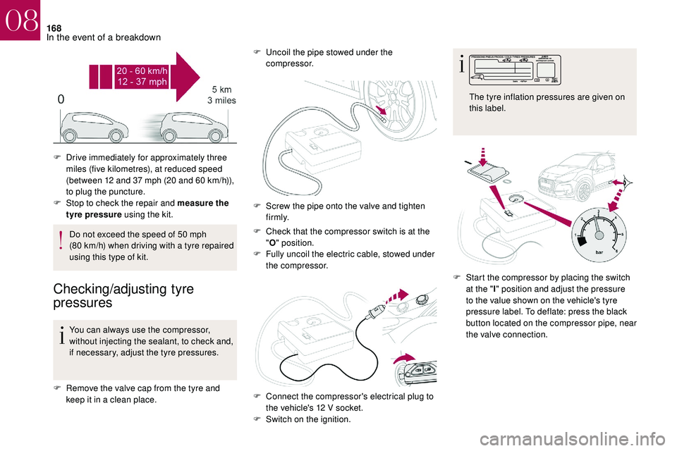
F
D
rive immediately for approximately three
miles (five kilometres), at reduced speed
(between 12 and 37 mph (20 and 60 km/h)),
to plug the puncture.
F
S
top to check the repair and measure the
tyre pressure using the kit. F
U
ncoil the pipe stowed under the
compressor.
F
S
crew the pipe onto the valve and tighten
f i r m l y.
F
C
onnect the compressor's electrical plug to
the vehicle's 12
V socket.
F
S
witch on the ignition.F
S
tart the compressor by placing the switch
at the " I" position and adjust the pressure
to the value shown on the vehicle's tyre
pressure label. To deflate: press the black
button located on the compressor pipe, near
the valve connection. The tyre inflation pressures are given on
this label.
08
In the event of a breakdown
Page 173 of 248
171
Removing a wheel
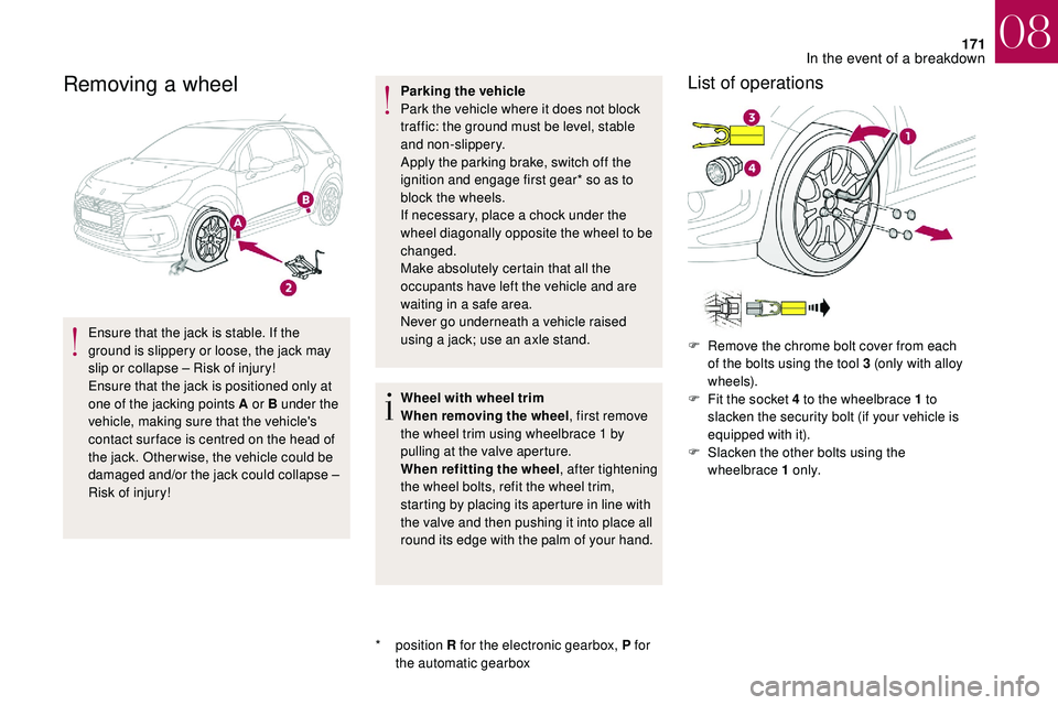
Ensure that the jack is stable. If the
ground is slippery or loose, the jack may
slip or collapse – Risk of injury!
Ensure that the jack is positioned only at
one of the jacking points A or B under the
vehicle, making sure that the vehicle's
contact sur face is centred on the head of
the jack. Otherwise, the vehicle could be
damaged and/or the jack could collapse –
Risk of injury!
*
position R for the electronic gearbox, P for
the automatic gearbox Parking the vehicle
Park the vehicle where it does not block
traffic: the ground must be level, stable
and non-slippery.
Apply the parking brake, switch off the
ignition and engage first gear* so as to
block the wheels.
If necessary, place a
chock under the
wheel diagonally opposite the wheel to be
changed.
Make absolutely certain that all the
occupants have left the vehicle and are
waiting in a safe area.
Never go underneath a vehicle raised
using a jack; use an axle stand.
Wheel with wheel trim
When removing the wheel , first remove
the wheel trim using wheelbrace 1
by
pulling at the valve aperture.
When refitting the wheel , after tightening
the wheel bolts, refit the wheel trim,
starting by placing its aperture in line with
the valve and then pushing it into place all
round its edge with the palm of your hand.
List of operations
F Remove the chrome bolt cover from each of the bolts using the tool 3 (only with alloy
w h e e l s).
F
F
it the socket 4 to the wheelbrace 1 to
slacken the security bolt (if your vehicle is
equipped with it).
F
S
lacken the other bolts using the
wheelbrace 1
o n l y.
08
In the event of a breakdown
Page 176 of 248

174
Changing a bulb
The headlamps have polycarbonate
lenses with a
protective coating:
F
d
o not clean them using a dr y or
abrasive cloth, nor with a
detergent
or solvent product,
F
u
se a sponge and soapy water or a pH
neutral product,
F
w
hen using a high pressure washer
on persistent marks, do not keep the
lance directed towards the lamps or
their edges for too long, so as not to
damage their protective coating and
seals.
Changing a
bulb must only be done with
the ignition off and after the headlamp has
been switched off for several minutes –
Risk of serious burns!
F
D
o not touch the bulb directly with your
fingers, use a
lint-free cloth.
It is essential only to use anti-ultraviolet
(UV) type bulbs, so as not to damage the
headlamp.
Always replace a
failed bulb with a new
bulb with the same type and specification.
Front lamps
Halogen headlamps
1. Direction indicators (PY21W amber).
2. Sidelamps (W5W).
3. Main beam headlamps (H1-55W).
4. Dipped beam headlamps (H7-55W).
5. LED foglamps.
6. LED daytime running lamps.
Direction indicators
Rapid flashing of the direction indicator
lamp (left or right) indicates that one of
the bulbs on the corresponding side has
failed.
F
T
urn the bulb holder a quarter turn and
remove it.
F
P
ull the bulb out and change it.
To refit, carry out these operations in reverse
o r d e r.
Amber colour bulbs, such as the direction
indicators, must be replaced by bulbs with
identical colour and specifications.
To refit, close the protective cover very
carefully to guarantee the leak-tightness
of the lamp.
08
In the event of a breakdown
Page 183 of 248
181
Changing a fuse
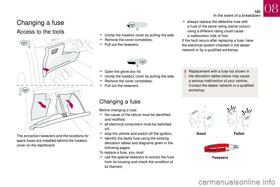
Access to the tools
The extraction tweezers and the locations for
spare fuses are installed behind the fusebox
cover on the dashboard.
Changing a fuse
F always replace the defective fuse with
a fuse of the same rating (same colour);
using a
different rating could cause
a
malfunction (risk of fire).
If the fault recurs after replacing a
fuse, have
the electrical system checked in the dealer
network or by a
qualified workshop.
Replacement with a
fuse not shown in
the allocation tables below may cause
a
serious malfunction of your vehicle.
Contact the dealer network or a
qualified
workshop.
F
U
nclip the fusebox cover by pulling the side.
F
R
emove the cover completely,
F
P
ull out the tweezers.
F
O
pen the glove box lid.
F
U
nclip the fusebox cover by pulling the side.
F
R
emove the cover completely,
F
P
ull out the tweezers.
Before changing a
fuse:
F
t
he cause of the failure must be identified
and rectified,
F
a
ll electrical consumers must be switched
of f,
F
s
top the vehicle and switch off the ignition,
F
I
dentify the faulty fuse using the existing
allocation tables and diagrams given in the
following pages.
To replace a
fuse, you must:
F
u
se the special tweezers to extract the fuse
from its housing and check the condition of
its filament, Good
Failed
Tw e e z e r s
08
In the event of a breakdown
Page 186 of 248
184
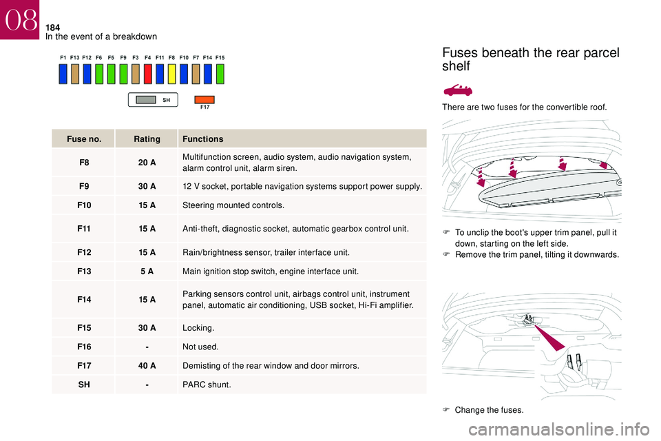
There are two fuses for the convertible roof.F
T
o unclip the boot's upper trim panel, pull it
down, starting on the left side.
F
R
emove the trim panel, tilting it downwards.
Fuse no.
Rating Functions
F8 20
A Multifunction screen, audio system, audio navigation system,
alarm control unit, alarm siren.
F9 30
A 12
V socket, portable navigation systems support power supply.
F10 15
A Steering mounted controls.
F11 15
A Anti-theft, diagnostic socket, automatic gearbox control unit.
F12 15
A Rain/brightness sensor, trailer interface unit.
F13 5
A Main ignition stop switch, engine interface unit.
F14 15
A Parking sensors control unit, airbags control unit, instrument
panel, automatic air conditioning, USB socket, Hi-Fi amplifier.
F15 30
A Locking.
F16 -Not used.
F17 40
A Demisting of the rear window and door mirrors.
SH -PARC shunt.
Fuses beneath the rear parcel
shelf
F Change the fuses.
08
In the event of a breakdown
Page 189 of 248
187
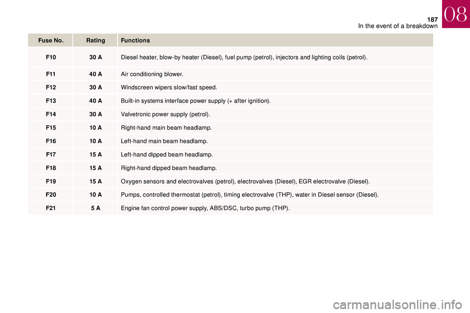
Fuse No.Rating Functions
F10 30
ADiesel heater, blow-by heater (Diesel), fuel pump (petrol), injectors and lighting coils (petrol).
F11 40
AAir conditioning blower.
F12 30
AWindscreen wipers slow/fast speed.
F13 40
ABuilt-in systems inter face power supply (+ after ignition).
F14 30
AValvetronic power supply (petrol).
F15 10
ARight-hand main beam headlamp.
F16 10
ALeft-hand main beam headlamp.
F17 15
ALeft-hand dipped beam headlamp.
F18 15
ARight-hand dipped beam headlamp.
F19 15
AOxygen sensors and electrovalves (petrol), electrovalves (Diesel), EGR electrovalve (Diesel).
F20 10
APumps, controlled thermostat (petrol), timing electrovalve (THP), water in Diesel sensor (Diesel).
F21 5
AEngine fan control power supply, ABS/DSC, turbo pump (THP).
08
In the event of a breakdown
Page 191 of 248
189
Access to the battery
The battery is located under the bonnet.
To access it:
F
o
pen the bonnet using the interior release
lever, then the exterior safety catch,
F
s
ecure the bonnet stay,
F
l
ift the plastic cover on the (+) terminal.The battery (-) terminal is not accessible.
A remote earth point is located on the
front left-hand wheel arch.
Starting using another battery
When your vehicle's battery is discharged, the
engine can be started using a backup battery
(external or from another vehicle) and jump
leads or a
battery booster. Never try to start the engine by connecting
a
battery charger.
Never use a 24 V or higher battery
b o o s t e r.
Check beforehand that the backup
battery has a nominal voltage of 12 V and
a capacity at least equal to that of the
discharged battery.
The two vehicles must not be in contact
with each other.
Switch off all the electrical consumers
on both vehicles (audio system, wipers,
lighting, etc.).
Make sure that the jump leads are not
close to moving parts of the engine (fan,
belts, etc.).
Do not disconnect the (+) terminal while
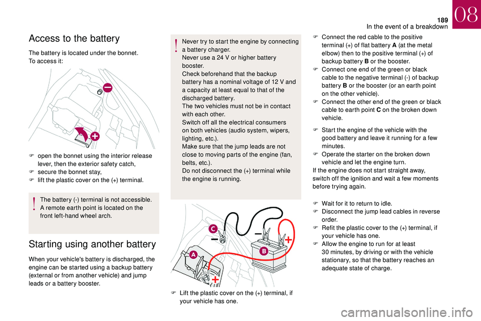
the engine is running. F
C
onnect the red cable to the positive
terminal (+) of flat battery A (at the metal
elbow) then to the positive terminal (+) of
backup battery B or the booster.
F
C
onnect one end of the green or black
cable to the negative terminal (-) of backup
battery B or the booster (or an earth point
on the other vehicle).
F
C
onnect the other end of the green or black
cable to earth point C on the broken down
vehicle.
F
L
ift the plastic cover on the (+) terminal, if
your vehicle has one. F
S
tart the engine of the vehicle with the
good battery and leave it running for a few
minutes.
F
O
perate the starter on the broken down
vehicle and let the engine turn.
If the engine does not start straight away,
switch off the ignition and wait a few moments
before trying again.
F
W
ait for it to return to idle.
F
D
isconnect the jump lead cables in reverse
o r d e r.
F
R
efit the plastic cover to the (+) terminal, if
your vehicle has one.
F
A
llow the engine to run for at least
30 minutes, by driving or with the vehicle
stationary, so that the battery reaches an
adequate state of charge.
08
In the event of a breakdown