light CITROEN RELAY 2019 Handbook (in English)
[x] Cancel search | Manufacturer: CITROEN, Model Year: 2019, Model line: RELAY, Model: CITROEN RELAY 2019Pages: 232, PDF Size: 8.21 MB
Page 109 of 232

107
The system is automatically deactivated
if the Stop & Start system is active.
The system will restart and check the
operating conditions again when the
vehicle moves off. Detection may be impeded:
-
i
f the markings on the road are worn,
-
i
f there is little contrast between the
markings on the road and the road
sur face.
The system may suffer inter ference or not
work correctly:
-
w
hen the vehicle is carrying a very
heavy load (even more so if the load is
not evenly spread),
-
w
hen the conditions of visibility are
poor (rain, fog, snow, etc.),
-
w
hen the lighting conditions are poor
(dazzling sun, shade, etc.),
-
i
f the windscreen is dirty or damaged
near the camera,
-
i
f any of the ABS, DSC, ASR or
Intelligent Traction Control systems are
out of service.
Malfunction
If a malfunction occurs, this warning
l amp comes on, accompanied by
an audible signal and confirmed by
a
message in the screen.
Have the system checked by a
CITROËN
dealer or a
qualified workshop.
6
Driving
Page 118 of 232
116
Fuel
The capacity of the tank is about 90 litres.
F uel tanks of different capacities may be fitted,
60
and 120 litres, depending on the engine.
Low fuel level
When the E (Empty) level is
reached, this warning lamp lights up.
You then have around 10
to 12 litres in
reser ve, depending on the capacity of the tank
and the engine.
Refuel without delay to avoid running out of
fuel.
Refilling
The fuel tank must be filled with the engine
off .
F
O
pen the fuel filler flap.
F
H
old the black cap with one hand.
F
W
ith the other hand, insert the key, then
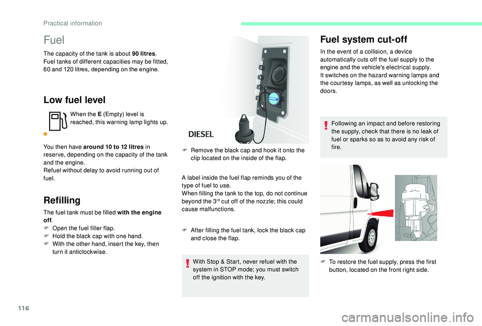
turn it anticlockwise. A label inside the fuel flap reminds you of the
type of fuel to use.
When filling the tank to the top, do not continue
beyond the 3
rd cut off of the nozzle; this could
cause malfunctions.
F
A
fter filling the fuel tank, lock the black cap
and close the flap.
With Stop & Start, never refuel with the
system in STOP mode; you must switch
off the ignition with the key.
F
R
emove the black cap and hook it onto the
clip located on the inside of the flap.
Fuel system cut-off
In the event of a collision, a device
a utomatically cuts off the fuel supply to the
engine and the vehicle's electrical supply.
It switches on the hazard warning lamps and
the courtesy lamps, as well as unlocking the
doors.
Following an impact and before restoring
the supply, check that there is no leak of
fuel or sparks so as to avoid any risk of
fire.
F
T
o restore the fuel supply, press the first
button, located on the front right side.
Practical information
Page 123 of 232
121
Before each use
Check that the towball is correctly locked by
verifying the following points:
-
t
he green mark on the locking wheel is in line
with the green mark on the towball,
-
t
he locking wheel is in contact with the towball,
-
t
he security lock is locked and the key
removed; the locking wheel can no longer be
operated,
-
t
he towball must not be able to move in its
carrier; test by trying to shake it with your hand.
During use
Never release the locking system with
a trailer or load carrier on the towball.
Never exceed the maximum authorised
weight for the vehicle (the Gross Vehicle
Weight – GV W), the trailer, or the sum of
the two (the Gross Train Weight – GTW).
Following use
When travelling without a trailer or load on
a towbar-mounted carrier, the towball must be
removed and the protective plug inserted in
the carrier. This measure applies particularly
where the towball might obscure visibility of the
number plate or its lighting.
Fitting the towball
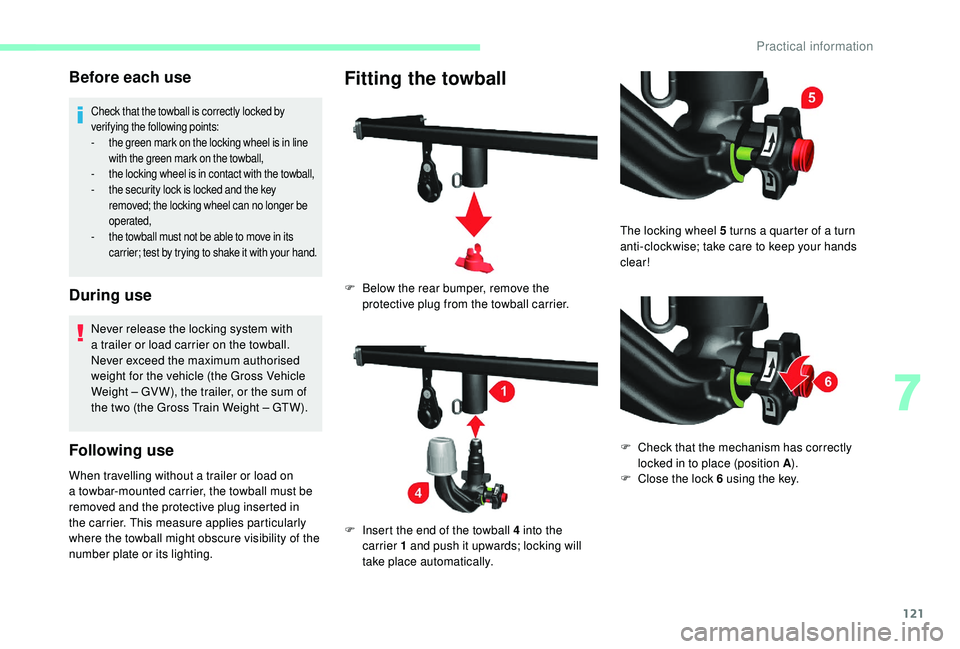
F Below the rear bumper, remove the protective plug from the towball carrier.
F
I
nsert the end of the towball 4 into the
carrier 1
and push it upwards; locking will
take place automatically. The locking wheel 5
turns a quarter of a turn
anti-clockwise; take care to keep your hands
clear!
F
C
heck that the mechanism has correctly
locked in to place (position A ).
F
C
lose the lock 6 using the key.
7
Practical information
Page 133 of 232
131
Brake disc wear
For information on checking brake
disc wear, contact a CITROËN or
a
qualified workshop.
Parking brake
If excessive travel or a loss of
e ffectiveness of this system is
noticed, the parking brake must
be checked, even between two
services.
This system must be checked by a
CITROËN
dealer or a
qualified workshop.
Diesel fuel filter
The Diesel fuel filter is located under the
bonnet, close to the brake fluid reser voir. If this warning lamp comes on, the
filter must be purged to remove
water.
You can also purge the fuel filter
regularly, every time the engine oil
is changed.
Purging water from the filterThe HDi engines use advanced technology.
All work must be done by personnel that
have had special training, which can be
ensured by going to a
CITROËN dealer or
a
qualified workshop.
Only use products recommended by
CITROËN or products of equivalent quality
and specification.
In order to optimise the operation of
components as important as those in the
braking system, CITROËN selects and
offers very specific products.
After washing the vehicle, dampness, or
in wintry conditions, ice can form on the
brake discs and pads: braking efficiency
may be reduced. Make light brake
applications to dry and defrost the brakes.
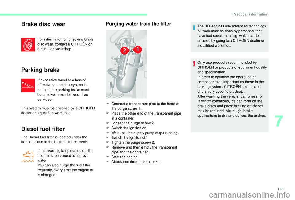
F
C
onnect a
transparent pipe to the head of
the purge screw 1 .
F
P
lace the other end of the transparent pipe
in a
container.
F
L
oosen the purge screw 2 .
F
S
witch the ignition on.
F
W
ait until the supply pump stops running.
F
S
witch the ignition off.
F
T
ighten the purge screw 2 .
F
R
emove and then empty the transparent
pipe and the container.
F
S
tart the engine.
F
C
heck that there are no leaks.
7
Practical information
Page 135 of 232
133
Keep AdBlue® out of the reach of children,
in its original container or bottle.
Never transfer AdBlue
® to another
container: it would lose its purity.
Never dilute AdBlue
® with water.
Never pour AdBlue® into the Diesel fuel
tank.
Bottles or containers are available from
a
CITROËN dealer or a
qualified workshop.
Recommendations on storage
AdBlue® freezes at about -11°C and
deteriorates above 25°C. It should be stored in
a
cool place and protected from direct sunlight.
Under these conditions, the fluid can be kept
for at least a
year.
If the fluid has frozen, it can be used once it has
completely thawed out at room temperature.
Never store bottles or containers of
AdBlue
® in your vehicle.
Procedure
In cold weather, before per forming the top up
ensure that the temperature of the vehicle is
above -11°C. Other wise the AdBlue
® may be
frozen and so cannot be poured into its tank.
Park your vehicle in a
warmer area for a few
hours to allow the top up to be carried out.
Use only AdBlue
® fluid that meets the
ISO
22241
standard.
F
B
efore topping up, ensure that the vehicle is
parked on a
flat and level sur face.
F
S
witch off the ignition to stop the engine
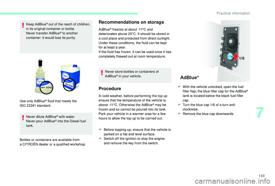
and remove the key from the switch. F
W
ith the vehicle unlocked, open the fuel
filler flap; the blue filler cap for the AdBlue
®
tank is located below the black fuel filler
cap.
F
T
urn the blue cap 1/6 of a turn anti-
clockwise.
F
R
emove the blue cap downwards.
7
Practical information
Page 147 of 232

145
If necessary you can remove the headlamp
unit:
F
D
epending on country of sale, remove the
extreme cold protection foam by making it
slide sideways towards the outside.
F
D
isconnect the electrical connector by
removing its locking ring.
F
R
emove the two headlamp unit fixing
screws.
F
M
ove the headlamp towards the centre of
the vehicle to extract it from its sliders. On
the left-hand side, be careful of the bonnet
st ay.
Main beam headlamps
Ty p e D , H7 - 55W
F R emove the cover by pulling on the rubber
tongue.
F
D
isconnect the electrical connector.
F
R
elease the retaining spring by pressing on
the central clip.
F
C
hange the bulb taking care to align the
metal part with the groove on the lamp.
Dipped beam headlamps
Ty p e D , H7 - 55W
F R emove the cover by pulling on the rubber
tongue.
F
D
isconnect the electrical connector.
F
R
elease the retaining spring by pressing on
the central clip.
F
C
hange the bulb taking care to align the
metal part with the grooves on the lamp.
Direction indicators
Ty p e A , W Y21W – 21W
F R emove the cover by pulling on the rubber
tongue.
F
T
urn the bulb holder a quarter turn anti-
clockwise.
F
C
hange the bulb.
F
O
pen and secure the bonnet with the stay.
F
T
o access the lamps and bulbs, reach
behind the headlamp unit. Ty p e A
, W21/5W – 21W and 5W
F
R
emove the cover by pulling on the rubber
tongue.
F
T
urn the bulb holder a quarter turn anti-
clockwise.
F
C
hange the bulb.
Sidelamps/daytime running
lamps
LED daytime running lamps
These light-emitting diode (LED) lamps act as
both daytime running lamps and sidelamps.
If your vehicle is fitted with LED daytime
running lamps, contact a CITROËN dealer.
8
In the event of a breakdown
Page 152 of 232
150
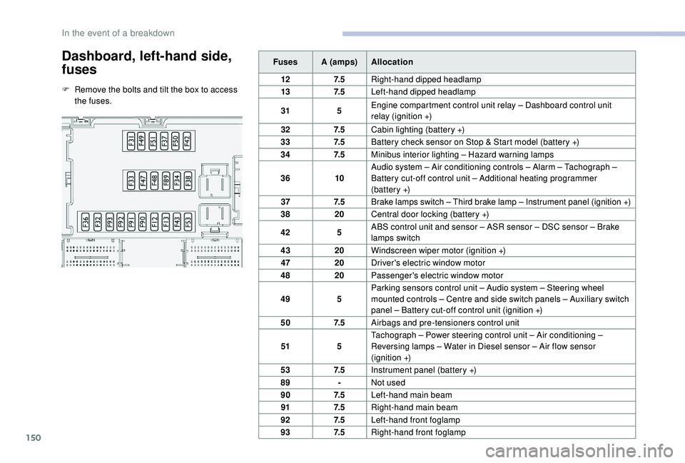
Dashboard, left-hand side,
fuses
F Remove the bolts and tilt the box to access the fuses. Fuses A (amps)
Allocation
12 7. 5Right-hand dipped headlamp
13 7. 5Left-hand dipped headlamp
31 5Engine compartment control unit relay – Dashboard control unit
relay (ignition +)
32 7. 5Cabin lighting (battery +)
33 7. 5Battery check sensor on Stop & Start model (battery +)
34 7. 5Minibus interior lighting – Hazard warning lamps
36 10Audio system – Air conditioning controls – Alarm – Tachograph
–
Battery cut-off control unit – Additional heating programmer
(battery
+)
37 7. 5Brake lamps switch – Third brake lamp – Instrument panel (ignition +)
38 20Central door locking (battery +)
42 5ABS control unit and sensor – ASR sensor – DSC sensor – Brake
lamps switch
43 20Windscreen wiper motor (ignition +)
47 20Driver's electric window motor
48 20Passenger's electric window motor
49 5Parking sensors control unit – Audio system – Steering wheel
mounted controls – Centre and side switch panels – Auxiliary switch
panel – Battery cut-off control unit (ignition +)
50 7. 5Airbags and pre-tensioners control unit
51 5Tachograph – Power steering control unit – Air conditioning –
Reversing lamps – Water in Diesel sensor – Air flow sensor
(ignition +)
53 7. 5Instrument panel (battery +)
89 -Not used
90 7. 5Left-hand main beam
91 7. 5Right-hand main beam
92 7. 5Left-hand front foglamp
93 7. 5Right-hand front foglamp
In the event of a breakdown
Page 154 of 232

152
Fuses in the engine
compartment
F Remove the nuts and tilt the box to access the fuses.
When you have finished, close the cover
very carefully. Fuses A (amps)
Allocation
1 40ABS pump feed
2 50Diesel pre-heating unit
3 30Ignition switch – Starter motor
4 40Fuel heater
5 20/50Cabin ventilation with additional programmable heating (battery +)
6 40/60Cabin fan maximum speed (battery +)
7 40/50/60 Cabin fan minimum speed (battery +)
8 40Cabin fan (ignition +)
9 15Rear 12
V socket (battery +)
10 15Horn
11 -Not used
14 15Front 12
V socket (battery +)
15 15Cigarette lighter (battery +)
16 -Not used
17 -Not used
18 7. 5Engine management control unit (battery +)
19 7. 5Air conditioning compressor
20 30Screenwash/headlamp wash pump
21 15Fuel pump supply
22 -Not used
23 30ABS solenoids
24 7. 5Auxiliary switch panel – Door mirror controls and folding (ignition +)
30 15Door mirror heating
In the event of a breakdown
Page 156 of 232
154
Starting using another
battery
Never try to start the engine by connecting
a battery charger.
Never use a
24 V or higher battery
b o o s t e r.
Check beforehand that the backup
battery has a
nominal voltage of 12 V and
a
capacity at least equal to that of the
discharged battery.
The two vehicles must not be in contact
with each other.
Switch off all the electrical consumers
on both vehicles (audio system, wipers,
lighting, etc.).
Make sure that the jump leads are not
close to moving parts of the engine (fan,
belts, etc.).
Do not disconnect the (+) terminal while
the engine is running.
After every reconnection of the battery, switch
on the ignition and wait 1
minute before
starting to allow the electronic systems to be
initialised. If slight difficulties are experienced
after this, please contact a
CITROËN dealer or
a
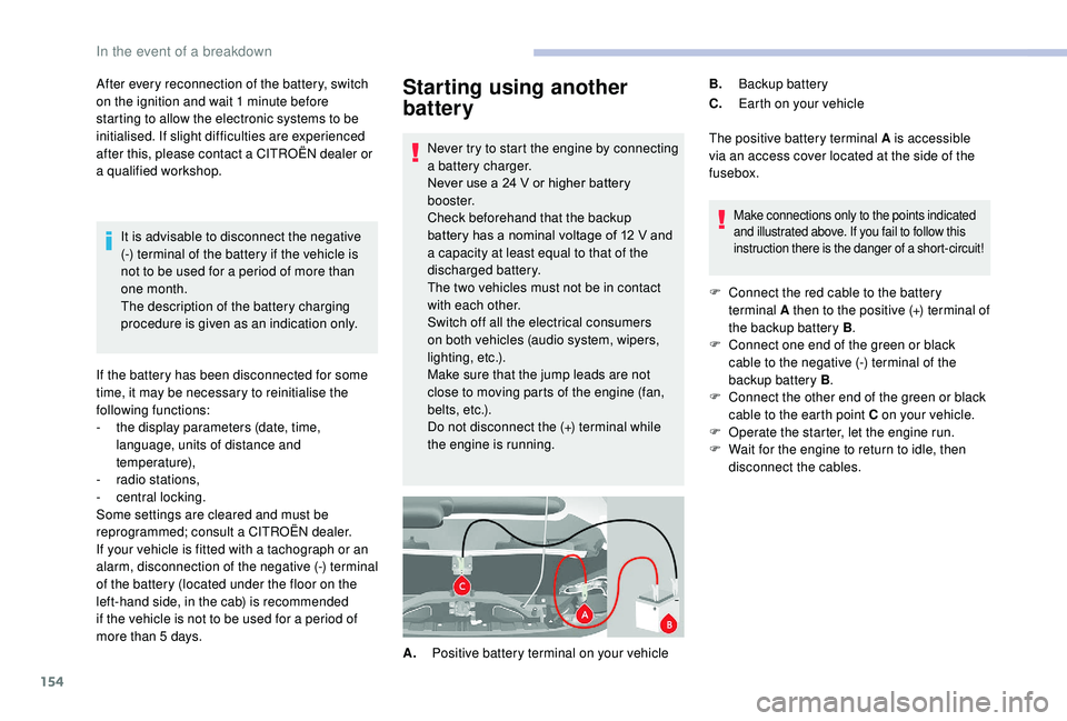
qualified workshop. The positive battery terminal A is accessible
via an access cover located at the side of the
fusebox.
Make connections only to the points indicated
and illustrated above. If you fail to follow this
instruction there is the danger of a
short-circuit!
F Connect the red cable to the battery terminal A then to the positive (+) terminal of
the backup battery B .
F
C
onnect one end of the green or black
cable to the negative (-) terminal of the
backup battery B .
F
C
onnect the other end of the green or black
cable to the earth point C on your vehicle.
F
O
perate the starter, let the engine run.
F
W
ait for the engine to return to idle, then
disconnect the cables.
A. Positive battery terminal on your vehicle B.
Backup battery
C. Earth on your vehicle
It is advisable to disconnect the negative
(-) terminal of the battery if the vehicle is
not to be used for a
period of more than
one month.
The description of the battery charging
procedure is given as an indication only.
If the battery has been disconnected for some
time, it may be necessary to reinitialise the
following functions:
-
t
he display parameters (date, time,
language, units of distance and
temperature),
-
r
adio stations,
-
c
entral locking.
Some settings are cleared and must be
reprogrammed; consult a
CITROËN dealer.
If your vehicle is fitted with a
tachograph or an
alarm, disconnection of the negative (-) terminal
of the battery (located under the floor on the
left-hand side, in the cab) is recommended
if the vehicle is not to be used for a
period of
more than 5
days.
In the event of a breakdown
Page 159 of 232

157
Engine technical data and
towed loads
Engines
The engine characteristics are given in the
vehicle's registration document, as well as in
sales brochures.The maximum power corresponds to the
value type-approved on a
test bed, under
conditions defined in European legislation
(Directive 1999/99/EC).
For more information, contact a
CITROËN
dealer or a
qualified workshop.
Weights and towed loads
The maximum weights and towed loads for
your vehicle are given in the registration
document, as well as in sales brochures.
These values are also given on the
manufacturer's plate or label.
For more information, contact a CITROËN
dealer or a
qualified workshop. The GTW and towed load values indicated are
valid up to a
maximum altitude of 1,000 metres.
The towed load value must be reduced by 10%
for each additional 1,000 metres of altitude.
The maximum authorised nose weight
corresponds to the weight permitted on the
towbar (can be dismantled with or without
a
tool).
GT W: Gross train weight.
High ambient temperatures may result
in a reduction in the per formance of
the vehicle to protect the engine. If the
ambient temperature is above 37°C, limit
the towed load.
Towing with a towing vehicle which is only
slightly laden may negatively affect its
handling.
Towing a
trailer increases the braking
distance.
When towing, never exceed the speed
of 62
mph (100 km/h) (obser ve the local
legislation in force). If the exterior temperature is high, it is
recommended that the engine be allowed
to idle for 1
to 2 minutes after the vehicle
comes to a stop, to facilitate its cooling.
9
Technical data