seat DAEWOO LACETTI 2004 Service Repair Manual
[x] Cancel search | Manufacturer: DAEWOO, Model Year: 2004, Model line: LACETTI, Model: DAEWOO LACETTI 2004Pages: 2643, PDF Size: 80.54 MB
Page 2346 of 2643

9G – 6IINTERIOR TRIM
DAEWOO V–121 BL4
Installation Procedure
1. Install the lower B–pillar trim panel.
2. Install the front rocker trim panel and the rear rock-
er trim panel to their original positions.
C–PILLAR TRIM PANEL
Removal Procedure
1. Remove the C–pillar trim panel.
Installation Procedure
1. Install the C–pillar trim panel.
DECK LID SILL PLATE COVER
Removal Procedure
1. Lower the rear seatback.
2. Remove the C–pillar trim panel.
3. Remove the rear seat belts. Refer to Section 8A,
Seat Belts.
4. Remove the child seat anchorage. Refer to Section
9H, Child Seat Anchorage.
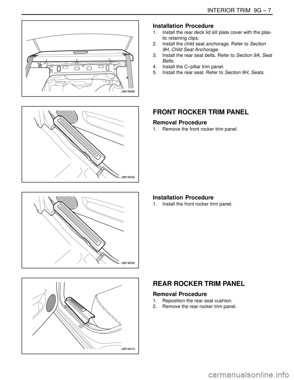
5. Remove the plastic retaining clips and the deck lid
sill plate cover.
Page 2347 of 2643
INTERIOR TRIM 9G – 7
DAEWOO V–121 BL4
Installation Procedure
1. Install the rear deck lid sill plate cover with the plas-
tic retaining clips.
2. Install the child seat anchorage. Refer to Section
9H, Child Seat Anchorage.
3. Install the rear seat belts. Refer to Section 9A, Seat
Belts.
4. Install the C–pillar trim panel.
5. Install the rear seat. Refer to Section 9H, Seats.
FRONT ROCKER TRIM PANEL
Removal Procedure
1. Remove the front rocker trim panel.
Installation Procedure
1. Install the front rocker trim panel.
REAR ROCKER TRIM PANEL
Removal Procedure
1. Reposition the rear seat cushion.
2. Remove the rear rocker trim panel.
Page 2348 of 2643

9G – 8IINTERIOR TRIM
DAEWOO V–121 BL4
Installation Procedure
1. Install the rear rocker trim panel.
2. Install the rear seat cushion to its original position.
FRONT WHEELHOUSE TRIM
Removal Procedure
1. Remove the screws and the front wheelhouse trim.
Installation Procedure
1. Install the front wheelhouse trim with the screws.
REAR WHEELHOUSE TRIM
Removal Procedure
1. Remove the rear seat. Refer to Section 9H, Seats.
2. Remove the seat belt bolt.
3. Remove the screws and the rear wheelhouse trim.
Page 2349 of 2643

INTERIOR TRIM 9G – 9
DAEWOO V–121 BL4
Installation Procedure
1. Install the rear wheelhouse trim with the screws.
2. Install the seat belt bolt.
3. Install the rear seat. Refer to Section 9H, Seats.
FLOOR CONSOLE
Removal Procedure
1. Disconnect the negative battery cable.
2. Remove the screw from the rear portion of the floor
console.
3. Remove the screws from the front portion of the
floor console.
4. Remove the floor console.
5. Disconnect the electrical connectors.
Installation Procedure
1. Connect the electrical connectors.
2. Install the floor console.
3. Install the front portion of the floor console with the
screws.
Page 2350 of 2643
9G – 10IINTERIOR TRIM
DAEWOO V–121 BL4
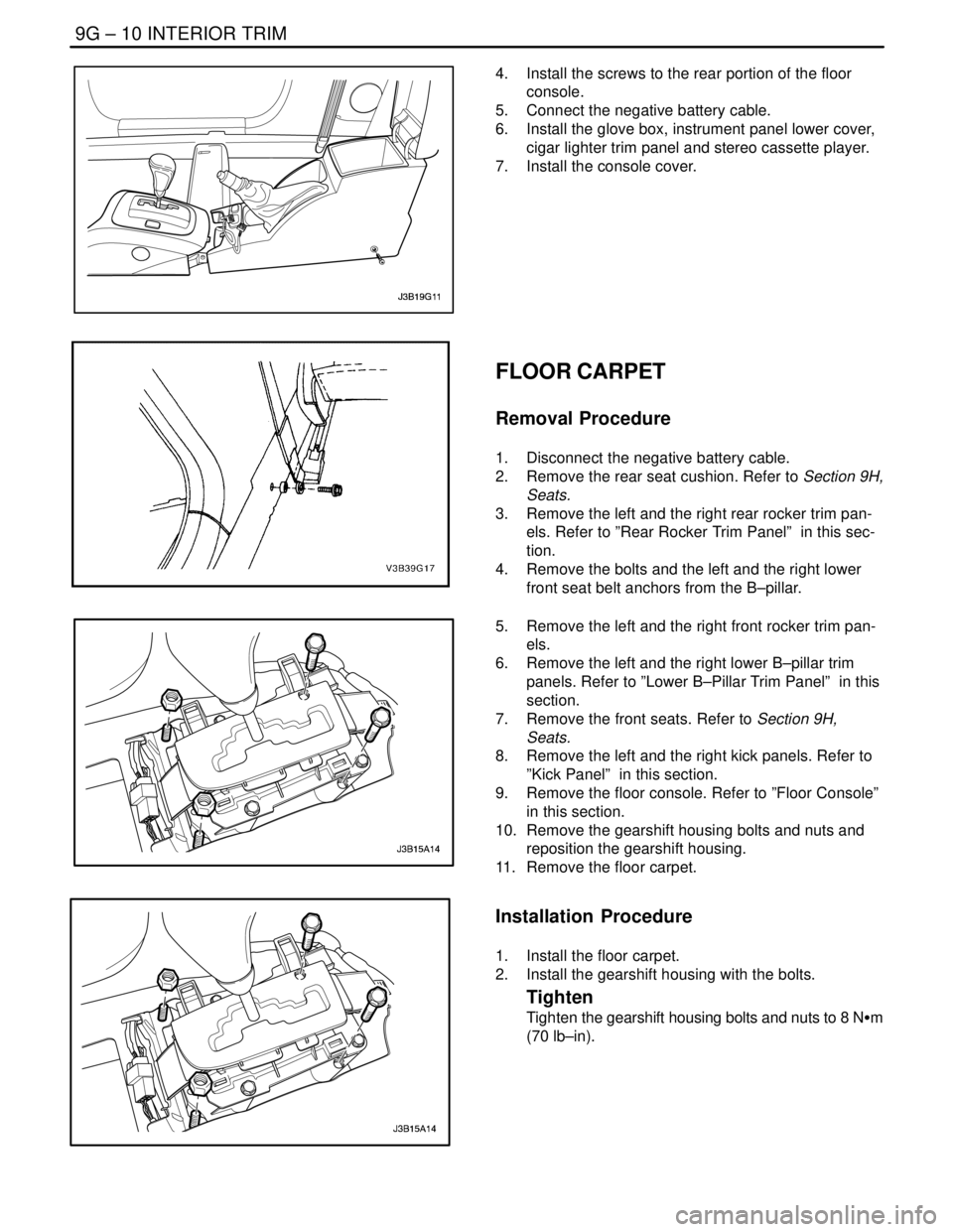
4. Install the screws to the rear portion of the floor
console.
5. Connect the negative battery cable.
6. Install the glove box, instrument panel lower cover,
cigar lighter trim panel and stereo cassette player.
7. Install the console cover.
FLOOR CARPET
Removal Procedure
1. Disconnect the negative battery cable.
2. Remove the rear seat cushion. Refer to Section 9H,
Seats.
3. Remove the left and the right rear rocker trim pan-
els. Refer to ”Rear Rocker Trim Panel” in this sec-
tion.
4. Remove the bolts and the left and the right lower
front seat belt anchors from the B–pillar.
5. Remove the left and the right front rocker trim pan-
els.
6. Remove the left and the right lower B–pillar trim
panels. Refer to ”Lower B–Pillar Trim Panel” in this
section.
7. Remove the front seats. Refer to Section 9H,
Seats.
8. Remove the left and the right kick panels. Refer to
”Kick Panel” in this section.
9. Remove the floor console. Refer to ”Floor Console”
in this section.
10. Remove the gearshift housing bolts and nuts and
reposition the gearshift housing.
11. Remove the floor carpet.
Installation Procedure
1. Install the floor carpet.
2. Install the gearshift housing with the bolts.
Tighten
Tighten the gearshift housing bolts and nuts to 8 NSm
(70 lb–in).
Page 2351 of 2643
INTERIOR TRIM 9G – 11
DAEWOO V–121 BL4
3. Install the floor console. Refer to ”Floor Console” in
this section.
4. Install the left and the right kick panels. Refer to
”Kick Panel” in this section.
5. Install the front seats. Refer to Section 9H, Seats.
6. Install the left and the right lower B–pillar trim pan-
els. Refer to ”Lower B–Pillar Trim Panel” in this
section.
7. Install the left and the right front rocker trim panels.
8. Install the left and the right lower front seat belt an-
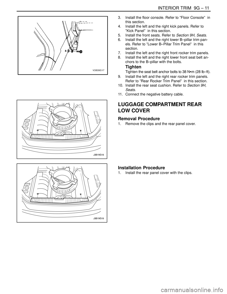
chors to the B–pillar with the bolts.
Tighten
Tighten the seat belt anchor bolts to 38 NSm (28 lb–ft).
9. Install the left and the right rear rocker trim panels.
Refer to ”Rear Rocker Trim Panel” in this section.
10. Install the rear seat cushion. Refer to Section 9H,
Seats.
11. Connect the negative battery cable.
LUGGAGE COMPARTMENT REAR
LOW COVER
Removal Procedure
1. Remove the clips and the rear panel cover.
Installation Procedure
1. Install the rear panel cover with the clips.
Page 2356 of 2643
9G – 16IINTERIOR TRIM
DAEWOO V–121 BL4
GENERAL DESCRIPTION
AND SYSTEM OPERATION
INTERIOR TRIM PANELS
The interior trim panels are molded plastic and fasten with
screws or plastic clips.
PRESSURE RELIEF VENT
When all the windows are closed and the ventilation sys-
tem is on, the addition of outside air to the interior of the
vehicle causes a positive pressure within the vehicle. To
relieve the pressure, air is released through a pressure re-
lief vent. The pressure relief vents are located at the rear
quarter of the vehicle, behind the bumper fascia.
FLOOR CONSOLE
The floor console fits over the tunnel in the floor of the ve-
hicle and extends from under the center of the instrument
panel to the rear seat area. The front portion of the consolecontains the cigar lighter and the transaxle shift lever. The
rear portion of the console contains the parking brake le-
ver, a cupholder, a storage compartment, and an ashtray
for the rear seat occupants.
The sensing and diagnostic module (SDM) for the airbag
system and the remote keyless entry module are located
under the console.
FLOOR CARPET
The one–piece floor carpet goes over both the front and
the rear floor pans.
REAR COMPARTMENT SECURITY
COVER (HATCHBACK)
A rear compartment security cover is provided on the
hatchback model. The security cover is attached to the
hatch and can be easily removed if more cargo space is
needed.
Page 2357 of 2643
SECTION : 9H
SEATS
CAUTION : Disconnect the negative battery cable before removing or installing any electrical unit or when a tool
or equipment could easily come in contact with exposed electrical terminals. Disconnecting this cable will help
prevent personal injury and damage to the vehicle. The ignition must also be in LOCK unless otherwise noted.
TABLE OF CONTENTS
SPECIFICATIONS9H–2 . . . . . . . . . . . . . . . . . . . . . . . . . .
Fastener Tightening Specifications 9H–2. . . . . . . . . . .
MAINTENANCE AND REPAIR9H–3 . . . . . . . . . . . . . . .
ON–VEHICLE SERVICE 9H–3. . . . . . . . . . . . . . . . . . . . .
Front Bucket Seat 9H–3. . . . . . . . . . . . . . . . . . . . . . . . .
Front Seatback 9H–4. . . . . . . . . . . . . . . . . . . . . . . . . . . .
Front Seat Cushion 9H–5. . . . . . . . . . . . . . . . . . . . . . . .
Lumbar Support Lever 9H–5. . . . . . . . . . . . . . . . . . . . . .
Height Adjustment Knobs 9H–6. . . . . . . . . . . . . . . . . . .
Front Seat Trim 9H–6. . . . . . . . . . . . . . . . . . . . . . . . . . . . Head Restraint 9H–7. . . . . . . . . . . . . . . . . . . . . . . . . . . .
Rear Seat Cushion 9H–8. . . . . . . . . . . . . . . . . . . . . . . . .
Split Rear Seatback 9H–8. . . . . . . . . . . . . . . . . . . . . . . .
Split Rear Seatback Hinge 9H–9. . . . . . . . . . . . . . . . . .
Rear Seat Center Armrest 9H–9. . . . . . . . . . . . . . . . . .
Seat Covers 9H–10. . . . . . . . . . . . . . . . . . . . . . . . . . . . .
Child Seat Anchorage 9H–10. . . . . . . . . . . . . . . . . . . . .
Hatchback Child Seat Anchorage 9H–11. . . . . . . . . . .
GENERAL DESCRIPTION AND SYSTEM
OPERATION9H–12 . . . . . . . . . . . . . . . . . . . . . . . . . . . . .
Seats 9H–12. . . . . . . . . . . . . . . . . . . . . . . . . . . . . . . . . . .
Page 2358 of 2643

9H – 2ISEATS
DAEWOO V–121 BL4
SPECIFICATIONS
FASTENER TIGHTENING SPECIFICATIONS
ApplicationNSmLb–FtLb–In
Armrest Nuts2418–
Front Seatback Bolts4533–
Front Seat Cover Screws12–106
Front Seat Cushion Bolts12–106
Front Seat Trim Screws12–106
Front Seat–to–Floor Bolts2518–
Rear Seatback Bolts2518–
Rear Seat Hinge Bolts4533–
Seat Recliner Lever Screw12–106
Slide Assembly Bolts2518–
Slide Assembly Screws10–89
Page 2359 of 2643
SEATS 9H – 3
DAEWOO V–121 BL4
MAINTENANCE AND REPAIR
ON–VEHICLE SERVICE
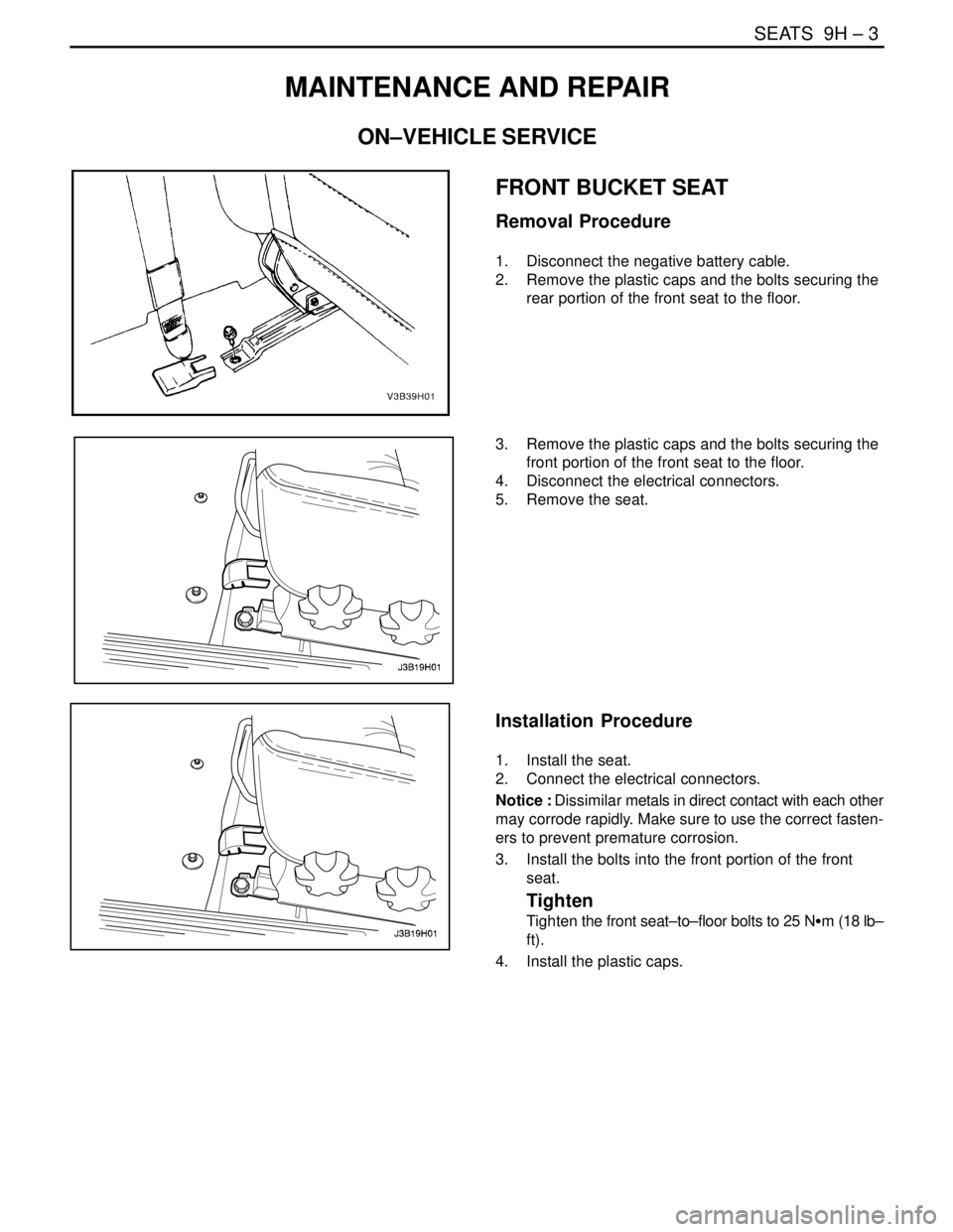
FRONT BUCKET SEAT
Removal Procedure
1. Disconnect the negative battery cable.
2. Remove the plastic caps and the bolts securing the
rear portion of the front seat to the floor.
3. Remove the plastic caps and the bolts securing the
front portion of the front seat to the floor.
4. Disconnect the electrical connectors.
5. Remove the seat.
Installation Procedure
1. Install the seat.
2. Connect the electrical connectors.
Notice : Dissimilar metals in direct contact with each other
may corrode rapidly. Make sure to use the correct fasten-
ers to prevent premature corrosion.
3. Install the bolts into the front portion of the front
seat.
Tighten
Tighten the front seat–to–floor bolts to 25 NSm (18 lb–
ft).
4. Install the plastic caps.