DAEWOO LACETTI 2004 Service Repair Manual
Manufacturer: DAEWOO, Model Year: 2004, Model line: LACETTI, Model: DAEWOO LACETTI 2004Pages: 2643, PDF Size: 80.54 MB
Page 171 of 2643
1.8L DOHC ENGINE MECHANICAL 1C2 – 51
DAEWOO V–121 BL4
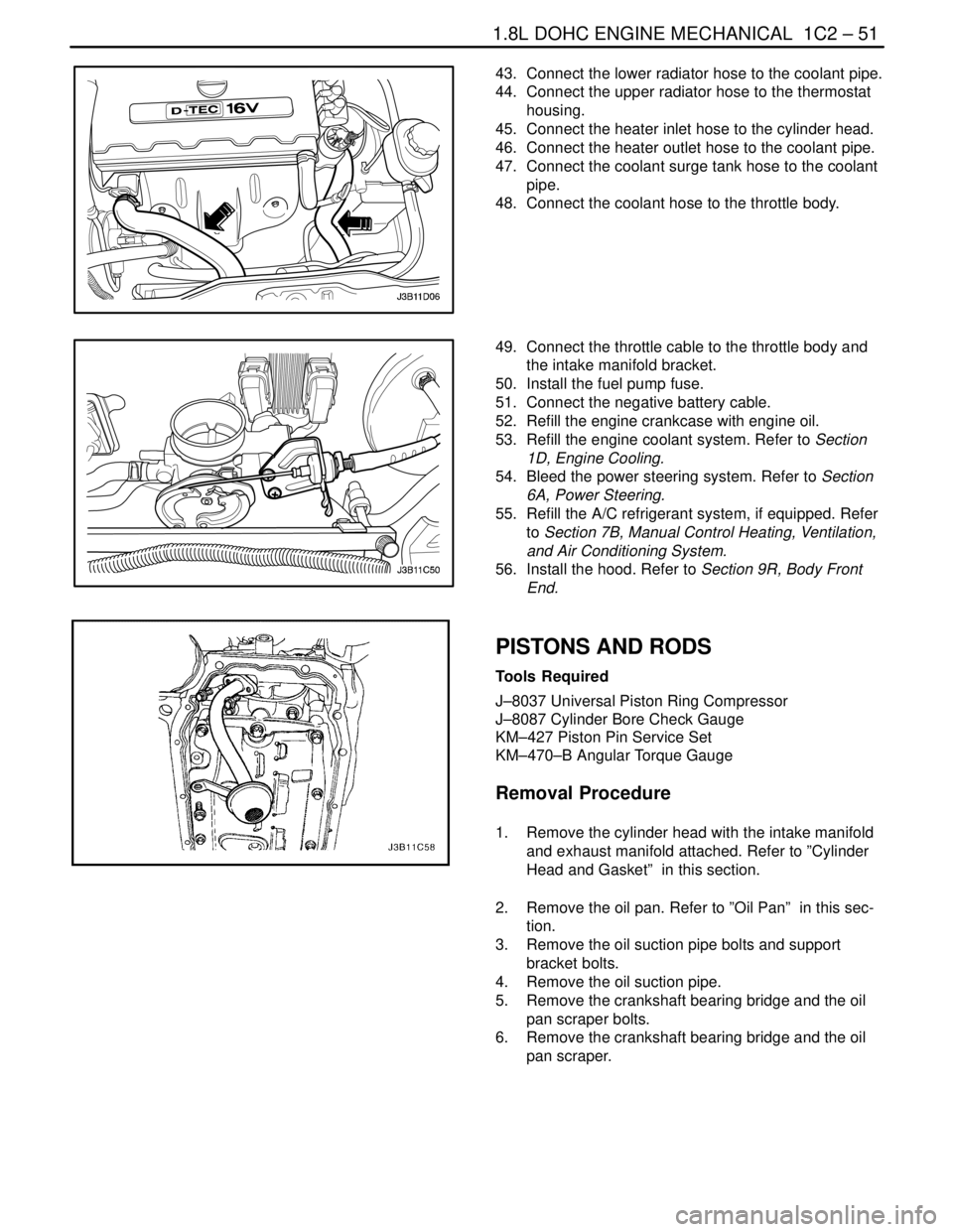
43. Connect the lower radiator hose to the coolant pipe.
44. Connect the upper radiator hose to the thermostat
housing.
45. Connect the heater inlet hose to the cylinder head.
46. Connect the heater outlet hose to the coolant pipe.
47. Connect the coolant surge tank hose to the coolant
pipe.
48. Connect the coolant hose to the throttle body.
49. Connect the throttle cable to the throttle body and
the intake manifold bracket.
50. Install the fuel pump fuse.
51. Connect the negative battery cable.
52. Refill the engine crankcase with engine oil.
53. Refill the engine coolant system. Refer to Section
1D, Engine Cooling.
54. Bleed the power steering system. Refer to Section
6A, Power Steering.
55. Refill the A/C refrigerant system, if equipped. Refer
to Section 7B, Manual Control Heating, Ventilation,
and Air Conditioning System.
56. Install the hood. Refer to Section 9R, Body Front
End.
PISTONS AND RODS
Tools Required
J–8037 Universal Piston Ring Compressor
J–8087 Cylinder Bore Check Gauge
KM–427 Piston Pin Service Set
KM–470–B Angular Torque Gauge
Removal Procedure
1. Remove the cylinder head with the intake manifold
and exhaust manifold attached. Refer to ”Cylinder
Head and Gasket” in this section.
2. Remove the oil pan. Refer to ”Oil Pan” in this sec-
tion.
3. Remove the oil suction pipe bolts and support
bracket bolts.
4. Remove the oil suction pipe.
5. Remove the crankshaft bearing bridge and the oil
pan scraper bolts.
6. Remove the crankshaft bearing bridge and the oil
pan scraper.
Page 172 of 2643
1C2 – 52I1.8L DOHC ENGINE MECHANICAL
DAEWOO V–121 BL4
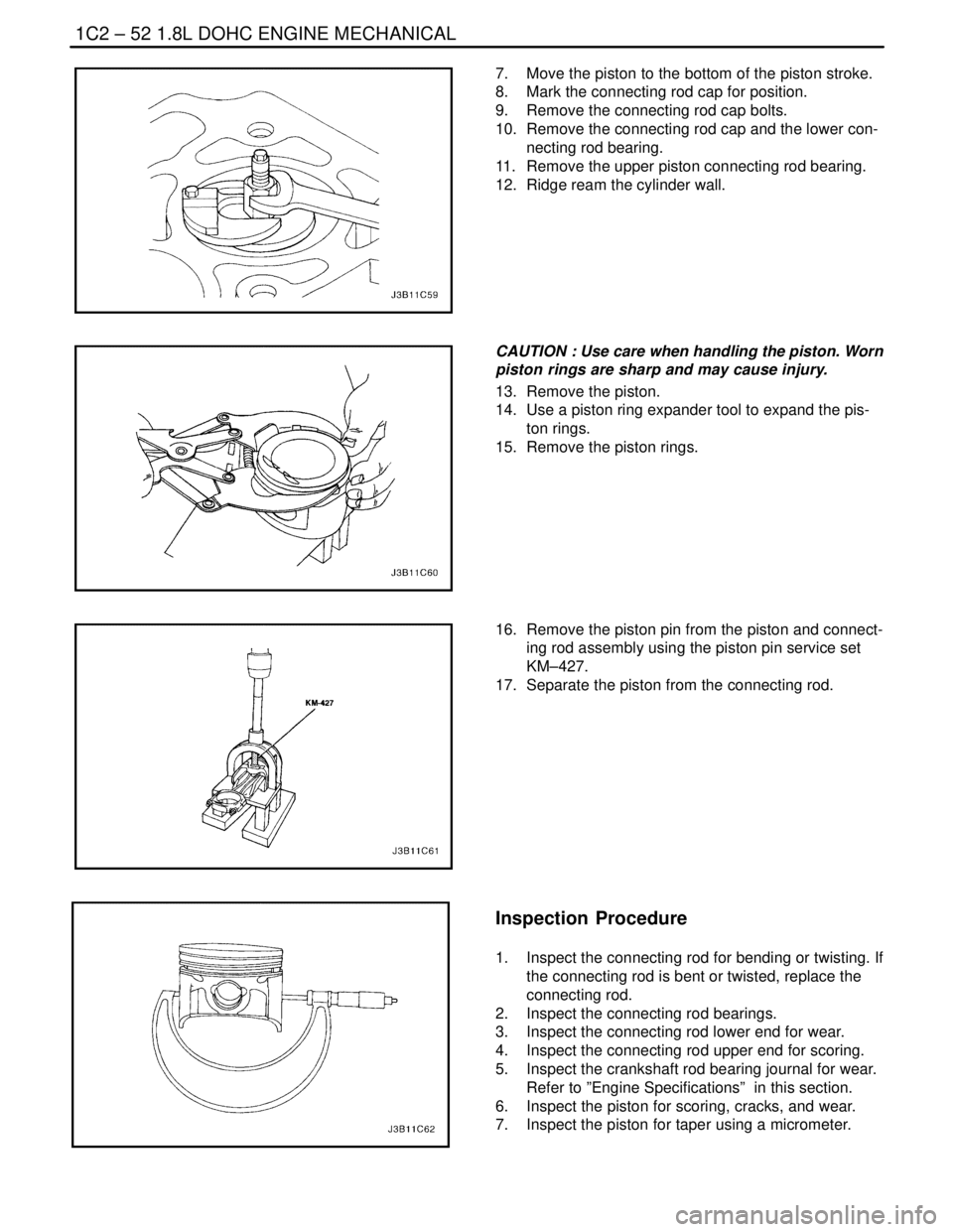
7. Move the piston to the bottom of the piston stroke.
8. Mark the connecting rod cap for position.
9. Remove the connecting rod cap bolts.
10. Remove the connecting rod cap and the lower con-
necting rod bearing.
11. Remove the upper piston connecting rod bearing.
12. Ridge ream the cylinder wall.
CAUTION : Use care when handling the piston. Worn
piston rings are sharp and may cause injury.
13. Remove the piston.
14. Use a piston ring expander tool to expand the pis-
ton rings.
15. Remove the piston rings.
16. Remove the piston pin from the piston and connect-
ing rod assembly using the piston pin service set
KM–427.
17. Separate the piston from the connecting rod.
Inspection Procedure
1. Inspect the connecting rod for bending or twisting. If
the connecting rod is bent or twisted, replace the
connecting rod.
2. Inspect the connecting rod bearings.
3. Inspect the connecting rod lower end for wear.
4. Inspect the connecting rod upper end for scoring.
5. Inspect the crankshaft rod bearing journal for wear.
Refer to ”Engine Specifications” in this section.
6. Inspect the piston for scoring, cracks, and wear.
7. Inspect the piston for taper using a micrometer.
Page 173 of 2643
1.8L DOHC ENGINE MECHANICAL 1C2 – 53
DAEWOO V–121 BL4
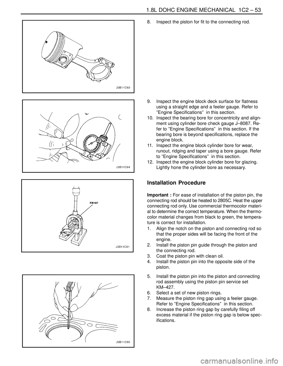
8. Inspect the piston for fit to the connecting rod.
9. Inspect the engine block deck surface for flatness
using a straight edge and a feeler gauge. Refer to
”Engine Specifications” in this section.
10. Inspect the bearing bore for concentricity and align-
ment using cylinder bore check gauge J–8087. Re-
fer to ”Engine Specifications” in this section. If the
bearing bore is beyond specifications, replace the
engine block.
11. Inspect the engine block cylinder bore for wear,
runout, ridging and taper using a bore gauge. Refer
to ”Engine Specifications” in this section.
12. Inspect the engine block cylinder bore for glazing.
Lightly hone the cylinder bore as necessary.
Installation Procedure
Important : For ease of installation of the piston pin, the
connecting rod should be heated to 2805C. Heat the upper
connecting rod only. Use commercial thermocolor materi-
al to determine the correct temperature. When the thermo-
color material changes from black to green, the tempera-
ture is correct for installation.
1. Align the notch on the piston and connecting rod so
that the proper sides will be facing the front of the
engine.
2. Install the piston pin guide through the piston and
the connecting rod.
3. Coat the piston pin with clean oil.
4. Install the piston pin into the opposite side of the
piston.
5. Install the piston pin into the piston and connecting
rod assembly using the piston pin service set
KM–427.
6. Select a set of new piston rings.
7. Measure the piston ring gap using a feeler gauge.
Refer to ”Engine Specifications” in this section.
8. Increase the piston ring gap by carefully filing off
excess material if the piston ring gap is below spec-
ifications.
Page 174 of 2643
1C2 – 54I1.8L DOHC ENGINE MECHANICAL
DAEWOO V–121 BL4
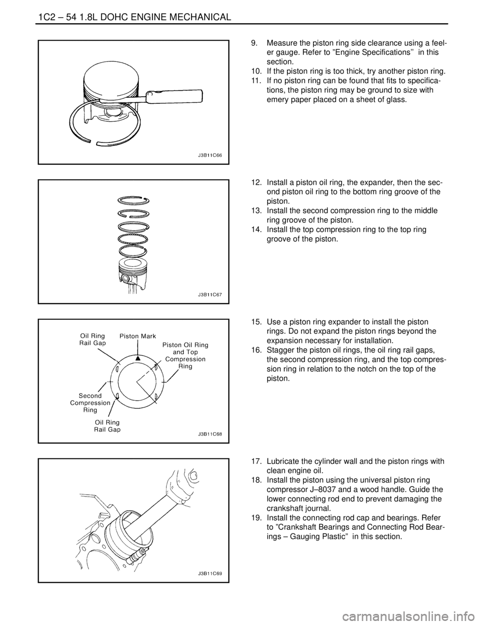
9. Measure the piston ring side clearance using a feel-
er gauge. Refer to ”Engine Specifications’’ in this
section.
10. If the piston ring is too thick, try another piston ring.
11. If no piston ring can be found that fits to specifica-
tions, the piston ring may be ground to size with
emery paper placed on a sheet of glass.
12. Install a piston oil ring, the expander, then the sec-
ond piston oil ring to the bottom ring groove of the
piston.
13. Install the second compression ring to the middle
ring groove of the piston.
14. Install the top compression ring to the top ring
groove of the piston.
15. Use a piston ring expander to install the piston
rings. Do not expand the piston rings beyond the
expansion necessary for installation.
16. Stagger the piston oil rings, the oil ring rail gaps,
the second compression ring, and the top compres-
sion ring in relation to the notch on the top of the
piston.
17. Lubricate the cylinder wall and the piston rings with
clean engine oil.
18. Install the piston using the universal piston ring
compressor J–8037 and a wood handle. Guide the
lower connecting rod end to prevent damaging the
crankshaft journal.
19. Install the connecting rod cap and bearings. Refer
to ”Crankshaft Bearings and Connecting Rod Bear-
ings – Gauging Plastic” in this section.
Page 175 of 2643
1.8L DOHC ENGINE MECHANICAL 1C2 – 55
DAEWOO V–121 BL4
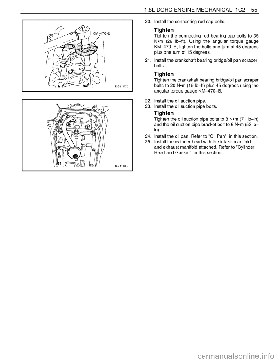
20. Install the connecting rod cap bolts.
Tighten
Tighten the connecting rod bearing cap bolts to 35
NSm (26 lb–ft). Using the angular torque gauge
KM–470–B, tighten the bolts one turn of 45 degrees
plus one turn of 15 degrees.
21. Install the crankshaft bearing bridge/oil pan scraper
bolts.
Tighten
Tighten the crankshaft bearing bridge/oil pan scraper
bolts to 20 NSm (15 lb–ft) plus 45 degrees using the
angular torque gauge KM–470–B.
22. Install the oil suction pipe.
23. Install the oil suction pipe bolts.
Tighten
Tighten the oil suction pipe bolts to 8 NSm (71 lb–in)
and the oil suction pipe bracket bolt to 6 NSm (53 lb–
in).
24. Install the oil pan. Refer to ”Oil Pan” in this section.
25. Install the cylinder head with the intake manifold
and exhaust manifold attached. Refer to ”Cylinder
Head and Gasket” in this section.
Page 176 of 2643
1C2 – 56I1.8L DOHC ENGINE MECHANICAL
DAEWOO V–121 BL4
UNIT REPAIR
CYLINDER HEAD AND VALVE TRAIN
COMPONENTS
Tools Required
MKM–571–B Gauge
KM–340–0 Cutter Set
KM–340–7 Guide Drift
KM–340–13 Cutters
KM–340–26 Cutters
KM–348 Valve Spring Compressor
KM–653 Adapter
KM–805 Valve Guide Reamer
Disassembly Procedure
1. Remove the cylinder head with the intake manifold
and the exhaust manifold attached. Refer to ”Cylin-
der Head and Gasket” in this section.
2. Remove the exhaust manifold heat shield bolts.
3. Remove the exhaust manifold heat shield.
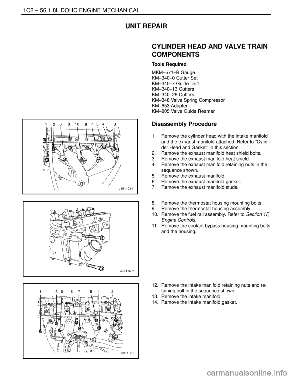
4. Remove the exhaust manifold retaining nuts in the
sequence shown.
5. Remove the exhaust manifold.
6. Remove the exhaust manifold gasket.
7. Remove the exhaust manifold studs.
8. Remove the thermostat housing mounting bolts.
9. Remove the thermostat housing assembly.
10. Remove the fuel rail assembly. Refer to Section 1F,
Engine Controls.
11. Remove the coolant bypass housing mounting bolts
and the housing.
12. Remove the intake manifold retaining nuts and re-
taining bolt in the sequence shown.
13. Remove the intake manifold.
14. Remove the intake manifold gasket.
Page 177 of 2643
1.8L DOHC ENGINE MECHANICAL 1C2 – 57
DAEWOO V–121 BL4
15. Remove the direct ignition system (DIS) coil and
the exhaust gas recirculation (EGR) mounting
bracket bolts.
16. Remove the DIS ignition coil and the EGR mount-
ing bracket and ignition wires.
17. Remove the intake manifold studs.
18. Remove the spark plugs.
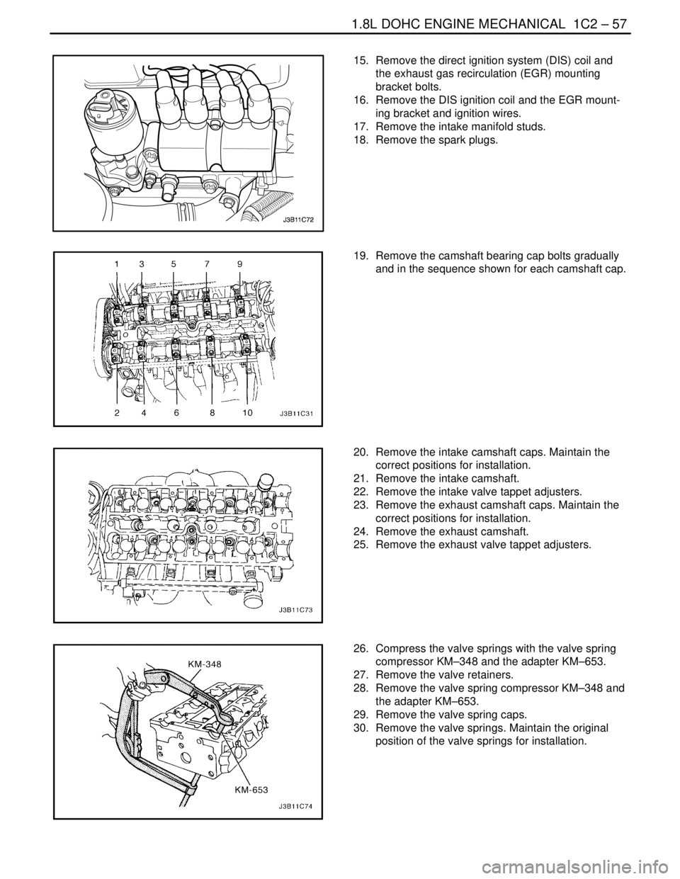
19. Remove the camshaft bearing cap bolts gradually
and in the sequence shown for each camshaft cap.
20. Remove the intake camshaft caps. Maintain the
correct positions for installation.
21. Remove the intake camshaft.
22. Remove the intake valve tappet adjusters.
23. Remove the exhaust camshaft caps. Maintain the
correct positions for installation.
24. Remove the exhaust camshaft.
25. Remove the exhaust valve tappet adjusters.
26. Compress the valve springs with the valve spring
compressor KM–348 and the adapter KM–653.
27. Remove the valve retainers.
28. Remove the valve spring compressor KM–348 and
the adapter KM–653.
29. Remove the valve spring caps.
30. Remove the valve springs. Maintain the original
position of the valve springs for installation.
Page 178 of 2643
1C2 – 58I1.8L DOHC ENGINE MECHANICAL
DAEWOO V–121 BL4
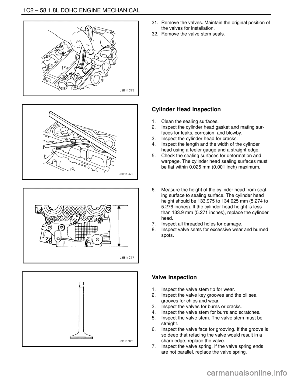
31. Remove the valves. Maintain the original position of
the valves for installation.
32. Remove the valve stem seals.
Cylinder Head Inspection
1. Clean the sealing surfaces.
2. Inspect the cylinder head gasket and mating sur-
faces for leaks, corrosion, and blowby.
3. Inspect the cylinder head for cracks.
4. Inspect the length and the width of the cylinder
head using a feeler gauge and a straight edge.
5. Check the sealing surfaces for deformation and
warpage. The cylinder head sealing surfaces must
be flat within 0.025 mm (0.001 inch) maximum.
6. Measure the height of the cylinder head from seal-
ing surface to sealing surface. The cylinder head
height should be 133.975 to 134.025 mm (5.274 to
5.276 inches). If the cylinder head height is less
than 133.9 mm (5.271 inches), replace the cylinder
head.
7. Inspect all threaded holes for damage.
8. Inspect valve seats for excessive wear and burned
spots.
Valve Inspection
1. Inspect the valve stem tip for wear.
2. Inspect the valve key grooves and the oil seal
grooves for chips and wear.
3. Inspect the valves for burns or cracks.
4. Inspect the valve stem for burrs and scratches.
5. Inspect the valve stem. The valve stem must be
straight.
6. Inspect the valve face for grooving. If the groove is
so deep that refacing the valve would result in a
sharp edge, replace the valve.
7. Inspect the valve spring. If the valve spring ends
are not parallel, replace the valve spring.
Page 179 of 2643
1.8L DOHC ENGINE MECHANICAL 1C2 – 59
DAEWOO V–121 BL4
8. Inspect the valve spring seating surface of the
valve rotators for wear or gouges. Replace as re-
quired.
Cleaning Procedure
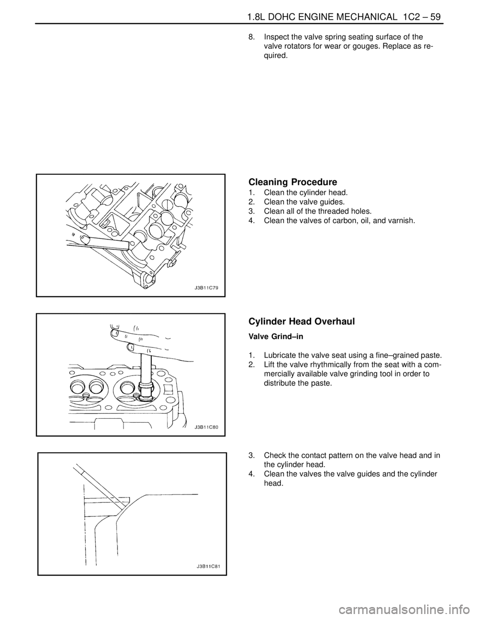
1. Clean the cylinder head.
2. Clean the valve guides.
3. Clean all of the threaded holes.
4. Clean the valves of carbon, oil, and varnish.
Cylinder Head Overhaul
Valve Grind–in
1. Lubricate the valve seat using a fine–grained paste.
2. Lift the valve rhythmically from the seat with a com-
mercially available valve grinding tool in order to
distribute the paste.
3. Check the contact pattern on the valve head and in
the cylinder head.
4. Clean the valves the valve guides and the cylinder
head.
Page 180 of 2643
1C2 – 60I1.8L DOHC ENGINE MECHANICAL
DAEWOO V–121 BL4
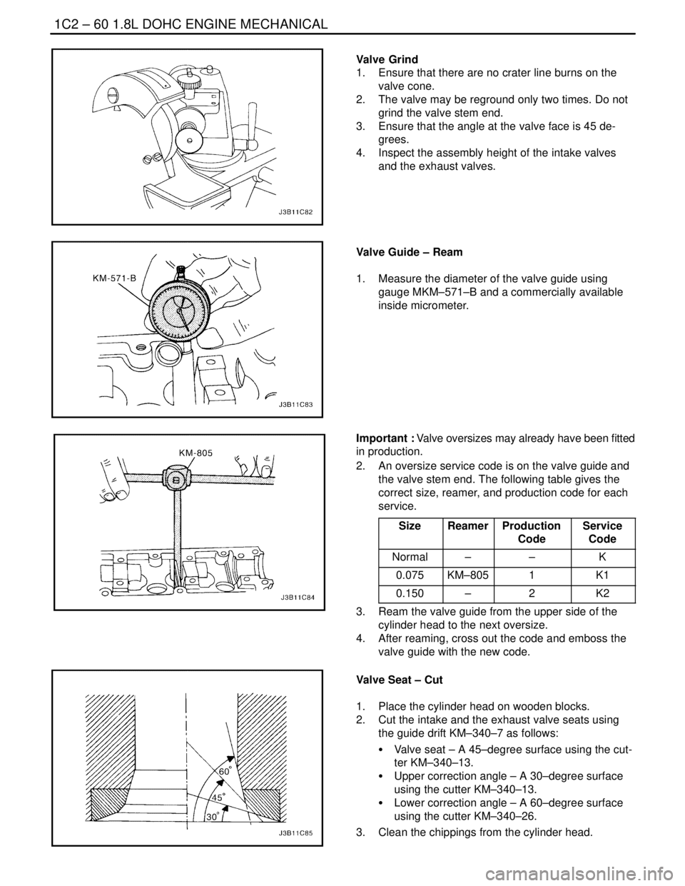
Valve Grind
1. Ensure that there are no crater line burns on the
valve cone.
2. The valve may be reground only two times. Do not
grind the valve stem end.
3. Ensure that the angle at the valve face is 45 de-
grees.
4. Inspect the assembly height of the intake valves
and the exhaust valves.
Valve Guide – Ream
1. Measure the diameter of the valve guide using
gauge MKM–571–B and a commercially available
inside micrometer.
Important : Valve oversizes may already have been fitted
in production.
2. An oversize service code is on the valve guide and
the valve stem end. The following table gives the
correct size, reamer, and production code for each
service.
Size
ReamerProduction
CodeService
Code
Normal––K
0.075KM–8051K1
0.150–2K2
3. Ream the valve guide from the upper side of the
cylinder head to the next oversize.
4. After reaming, cross out the code and emboss the
valve guide with the new code.
Valve Seat – Cut
1. Place the cylinder head on wooden blocks.
2. Cut the intake and the exhaust valve seats using
the guide drift KM–340–7 as follows:
S Valve seat – A 45–degree surface using the cut-
ter KM–340–13.
S Upper correction angle – A 30–degree surface
using the cutter KM–340–13.
S Lower correction angle – A 60–degree surface
using the cutter KM–340–26.
3. Clean the chippings from the cylinder head.