Front DAEWOO LACETTI 2004 Service User Guide
[x] Cancel search | Manufacturer: DAEWOO, Model Year: 2004, Model line: LACETTI, Model: DAEWOO LACETTI 2004Pages: 2643, PDF Size: 80.54 MB
Page 49 of 2643

1C1 – 6I1.4L/1.6L DOHC ENGINE MECHANICAL
DAEWOO V–121 BL4
Application Lb–InLb–Ft NSm
Oil Pump Bolts10–89
Oil Pump Rear Cover Bolts8–71
Oil Pump Retaining Bolts10–89
Oil Suction Pipe or Support Bracket Bolts10–89
Rear Timing Belt Cover Bolts10–89
Safety Relief Valve Bolt303022–
Spark Plugs2518–
Thermostat Housing Mounting Bolts2015–
Timing Belt Automatic Tensioner Bolts2518–
Timing Belt Idler Pulley Bolt4030–
Transaxle Bell Housing Bolts7555–
Transaxle Torque Converter Bolts4533–
Upper Front Timing Belt Cover Bolts10–89
Water Pump Retaining Bolts10–89
Page 52 of 2643
1.4L/1.6L DOHC ENGINE MECHANICAL 1C1 – 9
DAEWOO V–121 BL4
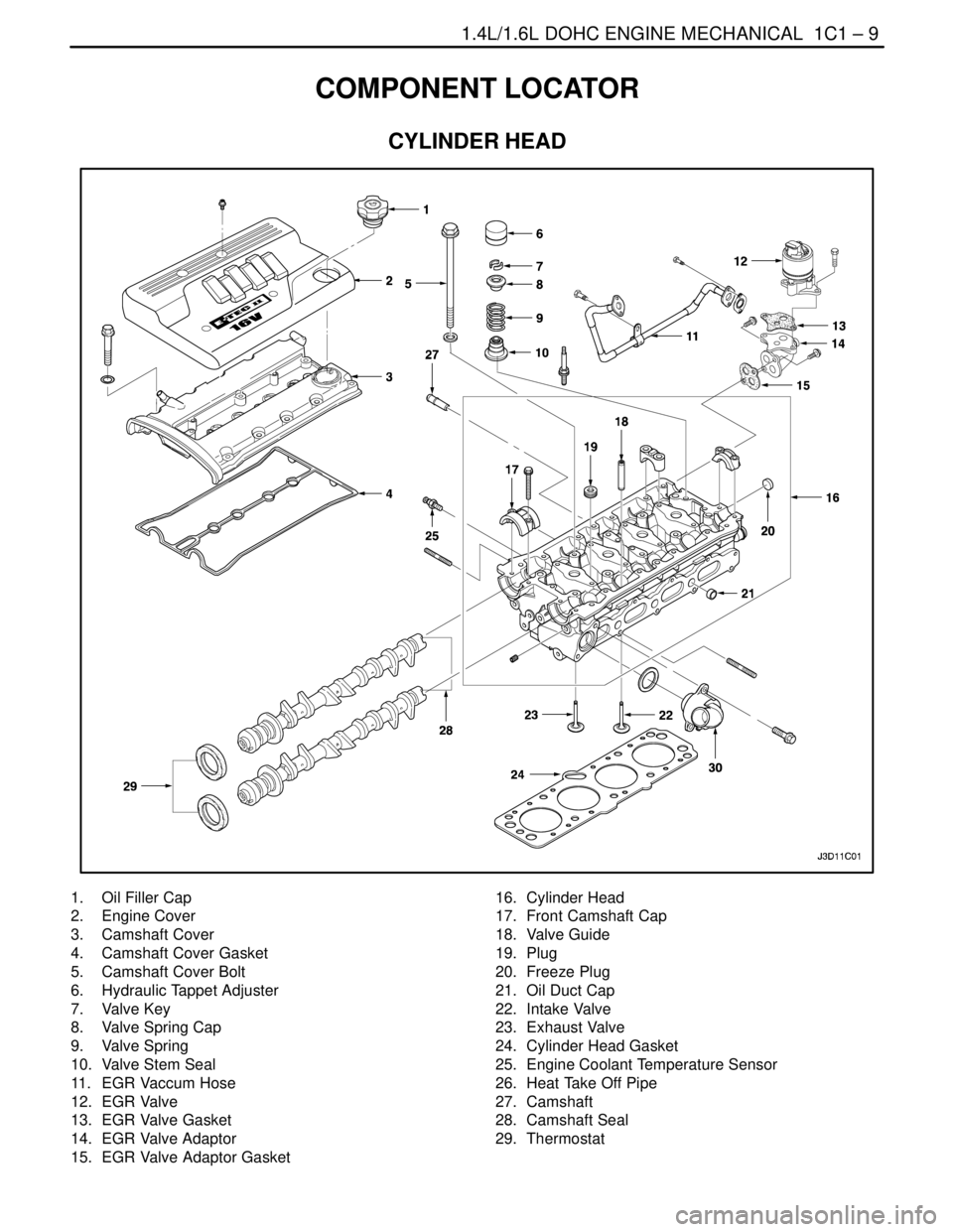
COMPONENT LOCATOR
CYLINDER HEAD
1. Oil Filler Cap
2. Engine Cover
3. Camshaft Cover
4. Camshaft Cover Gasket
5. Camshaft Cover Bolt
6. Hydraulic Tappet Adjuster
7. Valve Key
8. Valve Spring Cap
9. Valve Spring
10. Valve Stem Seal
11. EGR Vaccum Hose
12. EGR Valve
13. EGR Valve Gasket
14. EGR Valve Adaptor
15. EGR Valve Adaptor Gasket16. Cylinder Head
17. Front Camshaft Cap
18. Valve Guide
19. Plug
20. Freeze Plug
21. Oil Duct Cap
22. Intake Valve
23. Exhaust Valve
24. Cylinder Head Gasket
25. Engine Coolant Temperature Sensor
26. Heat Take Off Pipe
27. Camshaft
28. Camshaft Seal
29. Thermostat
Page 56 of 2643
1.4L/1.6L DOHC ENGINE MECHANICAL 1C1 – 13
DAEWOO V–121 BL4
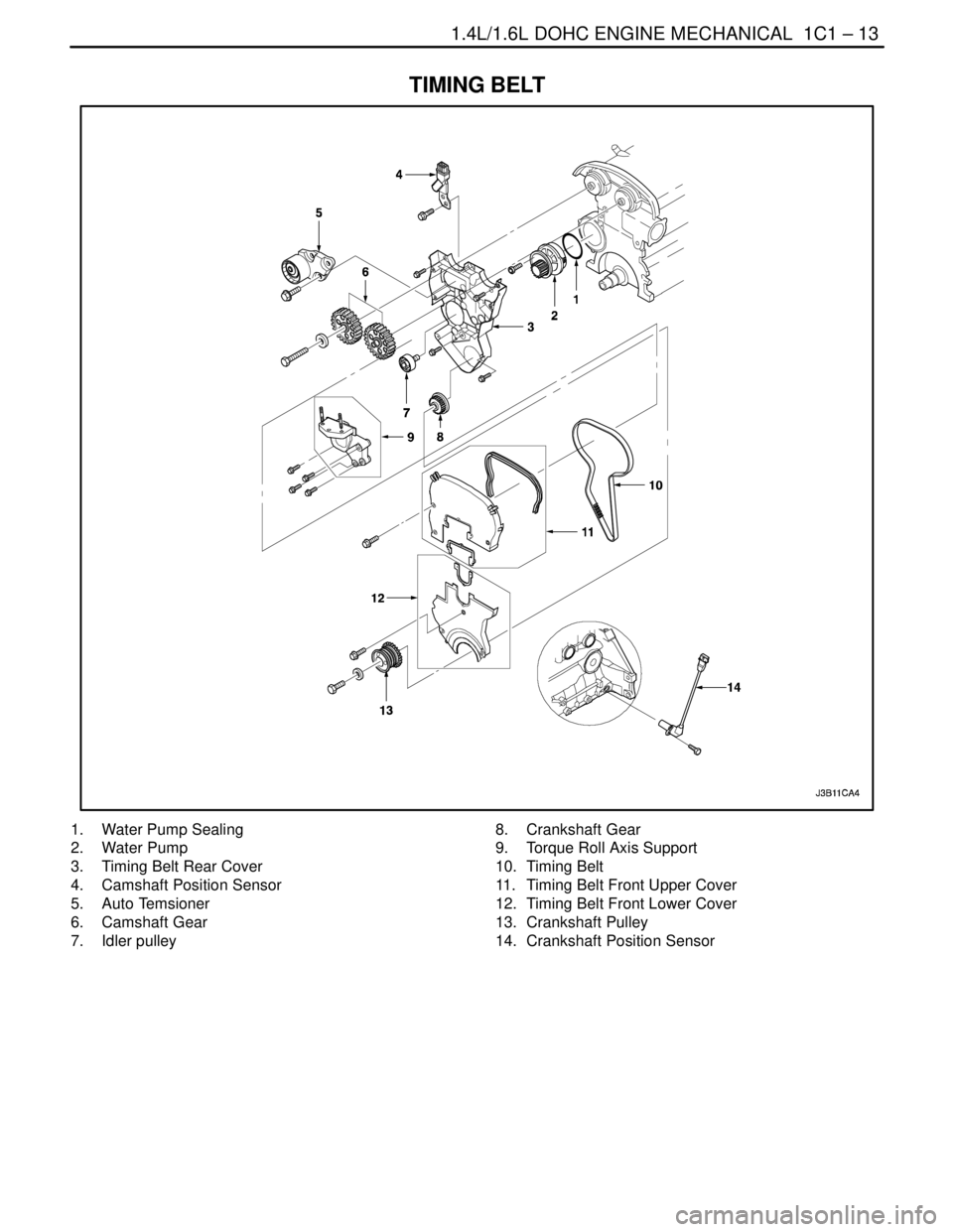
TIMING BELT
1. Water Pump Sealing
2. Water Pump
3. Timing Belt Rear Cover
4. Camshaft Position Sensor
5. Auto Temsioner
6. Camshaft Gear
7. Idler pulley8. Crankshaft Gear
9. Torque Roll Axis Support
10. Timing Belt
11. Timing Belt Front Upper Cover
12. Timing Belt Front Lower Cover
13. Crankshaft Pulley
14. Crankshaft Position Sensor
Page 66 of 2643
1.4L/1.6L DOHC ENGINE MECHANICAL 1C1 – 23
DAEWOO V–121 BL4
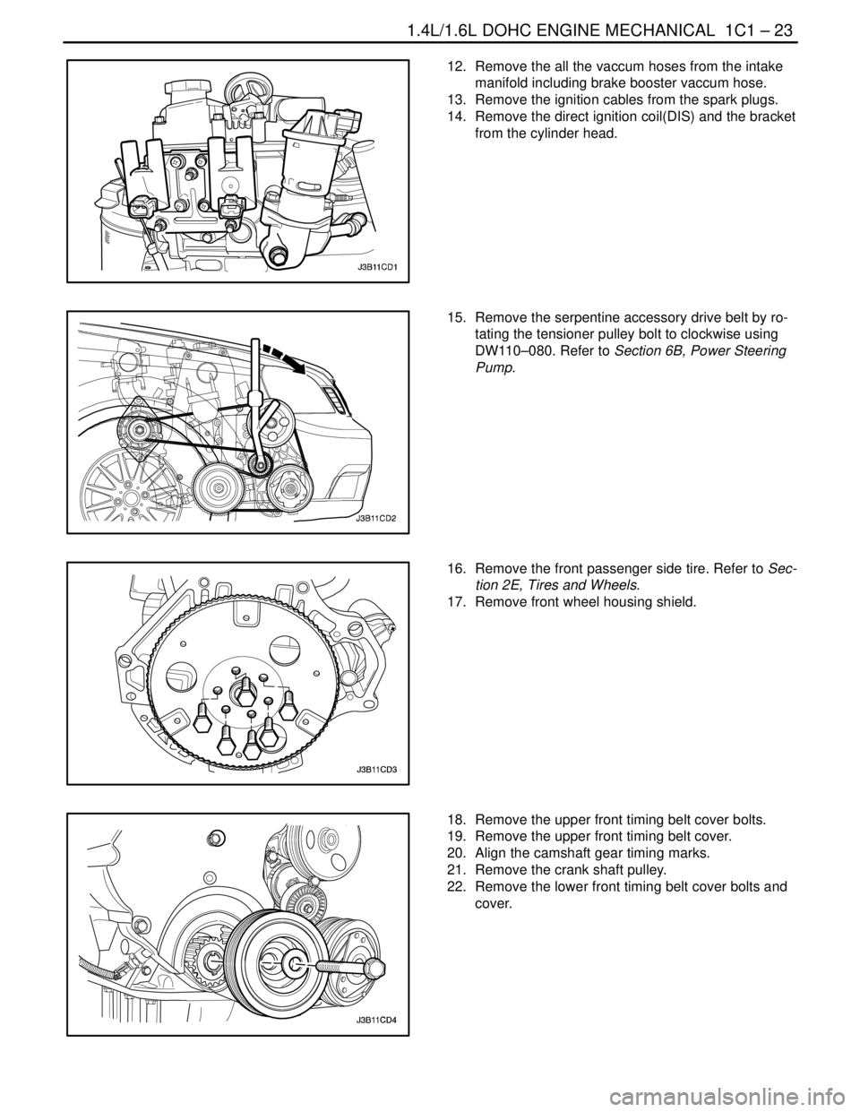
12. Remove the all the vaccum hoses from the intake
manifold including brake booster vaccum hose.
13. Remove the ignition cables from the spark plugs.
14. Remove the direct ignition coil(DIS) and the bracket
from the cylinder head.
15. Remove the serpentine accessory drive belt by ro-
tating the tensioner pulley bolt to clockwise using
DW110–080. Refer to Section 6B, Power Steering
Pump.
16. Remove the front passenger side tire. Refer to Sec-
tion 2E, Tires and Wheels.
17. Remove front wheel housing shield.
18. Remove the upper front timing belt cover bolts.
19. Remove the upper front timing belt cover.
20. Align the camshaft gear timing marks.
21. Remove the crank shaft pulley.
22. Remove the lower front timing belt cover bolts and
cover.
Page 70 of 2643
1.4L/1.6L DOHC ENGINE MECHANICAL 1C1 – 27
DAEWOO V–121 BL4
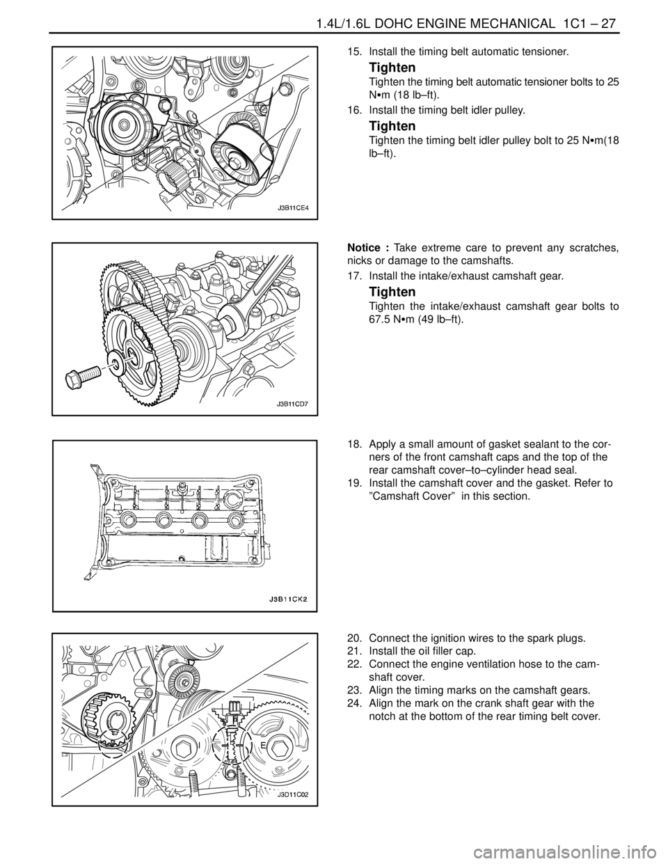
15. Install the timing belt automatic tensioner.
Tighten
Tighten the timing belt automatic tensioner bolts to 25
NSm (18 lb–ft).
16. Install the timing belt idler pulley.
Tighten
Tighten the timing belt idler pulley bolt to 25 NSm(18
lb–ft).
Notice : Take extreme care to prevent any scratches,
nicks or damage to the camshafts.
17. Install the intake/exhaust camshaft gear.
Tighten
Tighten the intake/exhaust camshaft gear bolts to
67.5 NSm (49 lb–ft).
18. Apply a small amount of gasket sealant to the cor-
ners of the front camshaft caps and the top of the
rear camshaft cover–to–cylinder head seal.
19. Install the camshaft cover and the gasket. Refer to
”Camshaft Cover” in this section.
20. Connect the ignition wires to the spark plugs.
21. Install the oil filler cap.
22. Connect the engine ventilation hose to the cam-
shaft cover.
23. Align the timing marks on the camshaft gears.
24. Align the mark on the crank shaft gear with the
notch at the bottom of the rear timing belt cover.
Page 71 of 2643
1C1 – 28I1.4L/1.6L DOHC ENGINE MECHANICAL
DAEWOO V–121 BL4
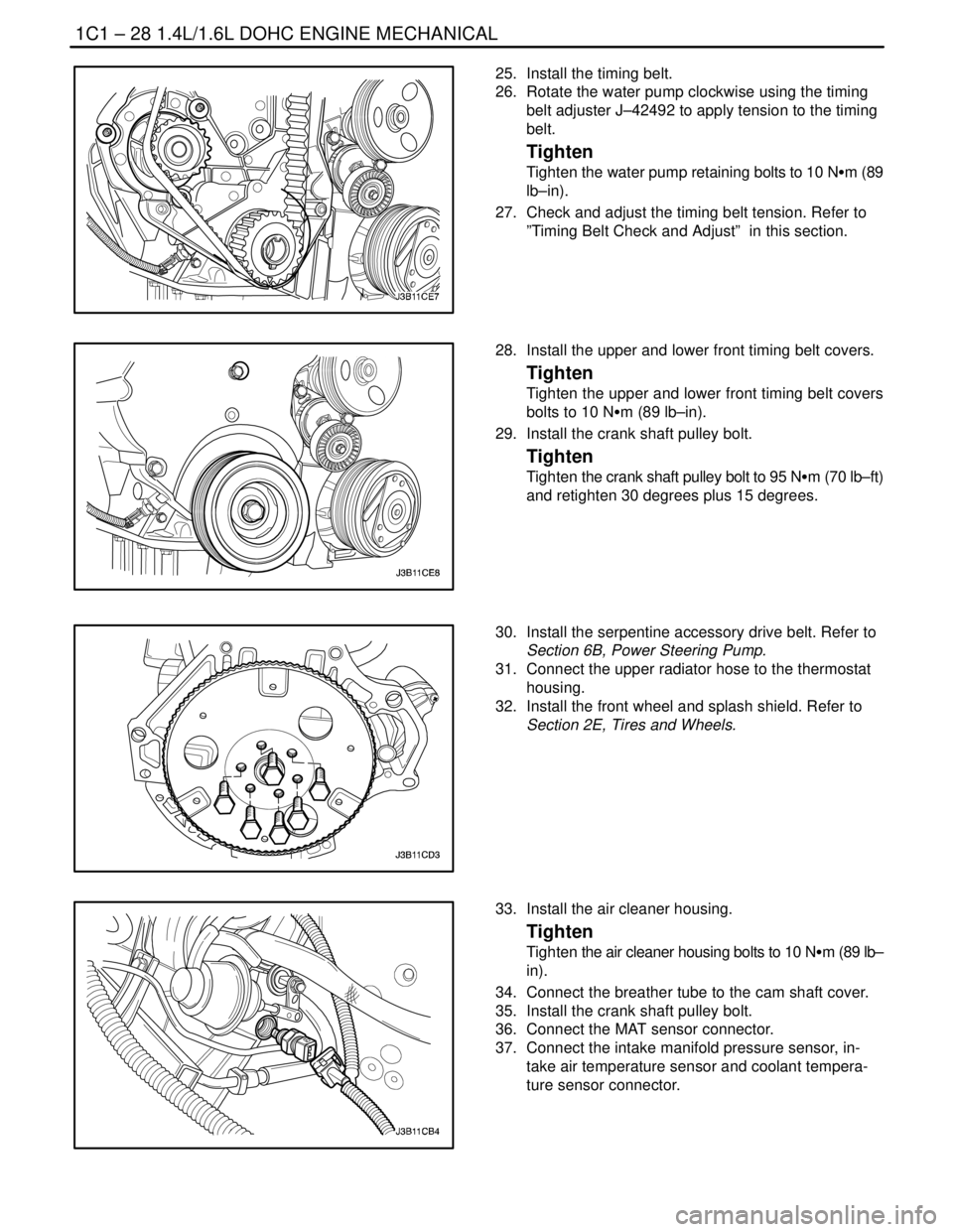
25. Install the timing belt.
26. Rotate the water pump clockwise using the timing
belt adjuster J–42492 to apply tension to the timing
belt.
Tighten
Tighten the water pump retaining bolts to 10 NSm (89
lb–in).
27. Check and adjust the timing belt tension. Refer to
”Timing Belt Check and Adjust” in this section.
28. Install the upper and lower front timing belt covers.
Tighten
Tighten the upper and lower front timing belt covers
bolts to 10 NSm (89 lb–in).
29. Install the crank shaft pulley bolt.
Tighten
Tighten the crank shaft pulley bolt to 95 NSm (70 lb–ft)
and retighten 30 degrees plus 15 degrees.
30. Install the serpentine accessory drive belt. Refer to
Section 6B, Power Steering Pump.
31. Connect the upper radiator hose to the thermostat
housing.
32. Install the front wheel and splash shield. Refer to
Section 2E, Tires and Wheels.
33. Install the air cleaner housing.
Tighten
Tighten the air cleaner housing bolts to 10 NSm (89 lb–
in).
34. Connect the breather tube to the cam shaft cover.
35. Install the crank shaft pulley bolt.
36. Connect the MAT sensor connector.
37. Connect the intake manifold pressure sensor, in-
take air temperature sensor and coolant tempera-
ture sensor connector.
Page 74 of 2643
1.4L/1.6L DOHC ENGINE MECHANICAL 1C1 – 31
DAEWOO V–121 BL4
TIMING BELT CHECK AND ADJUST
Tools Required
J–42492 Timing Belt Adjuster
KM–470–B Angular Torque Gauge
Adjustment Procedure
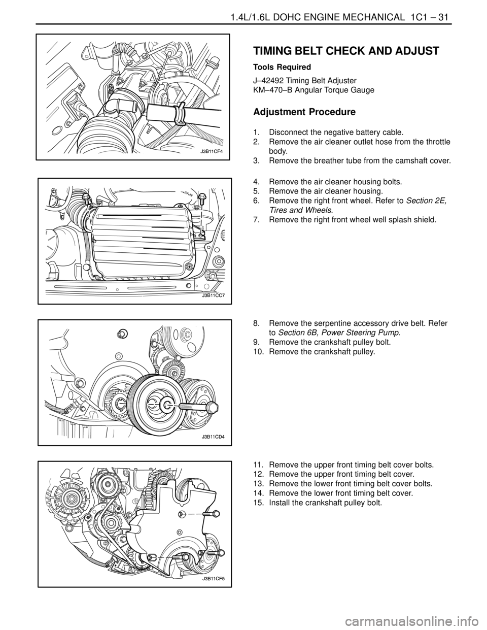
1. Disconnect the negative battery cable.
2. Remove the air cleaner outlet hose from the throttle
body.
3. Remove the breather tube from the camshaft cover.
4. Remove the air cleaner housing bolts.
5. Remove the air cleaner housing.
6. Remove the right front wheel. Refer to Section 2E,
Tires and Wheels.
7. Remove the right front wheel well splash shield.
8. Remove the serpentine accessory drive belt. Refer
to Section 6B, Power Steering Pump.
9. Remove the crankshaft pulley bolt.
10. Remove the crankshaft pulley.
11. Remove the upper front timing belt cover bolts.
12. Remove the upper front timing belt cover.
13. Remove the lower front timing belt cover bolts.
14. Remove the lower front timing belt cover.
15. Install the crankshaft pulley bolt.
Page 76 of 2643
1.4L/1.6L DOHC ENGINE MECHANICAL 1C1 – 33
DAEWOO V–121 BL4
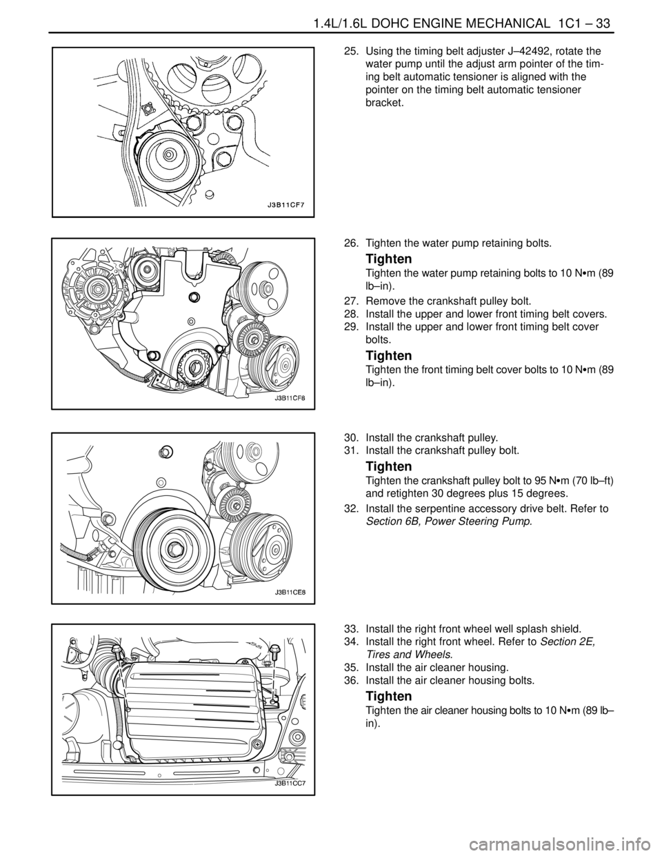
25. Using the timing belt adjuster J–42492, rotate the
water pump until the adjust arm pointer of the tim-
ing belt automatic tensioner is aligned with the
pointer on the timing belt automatic tensioner
bracket.
26. Tighten the water pump retaining bolts.
Tighten
Tighten the water pump retaining bolts to 10 NSm (89
lb–in).
27. Remove the crankshaft pulley bolt.
28. Install the upper and lower front timing belt covers.
29. Install the upper and lower front timing belt cover
bolts.
Tighten
Tighten the front timing belt cover bolts to 10 NSm (89
lb–in).
30. Install the crankshaft pulley.
31. Install the crankshaft pulley bolt.
Tighten
Tighten the crankshaft pulley bolt to 95 NSm (70 lb–ft)
and retighten 30 degrees plus 15 degrees.
32. Install the serpentine accessory drive belt. Refer to
Section 6B, Power Steering Pump.
33. Install the right front wheel well splash shield.
34. Install the right front wheel. Refer to Section 2E,
Tires and Wheels.
35. Install the air cleaner housing.
36. Install the air cleaner housing bolts.
Tighten
Tighten the air cleaner housing bolts to 10 NSm (89 lb–
in).
Page 77 of 2643
1C1 – 34I1.4L/1.6L DOHC ENGINE MECHANICAL
DAEWOO V–121 BL4
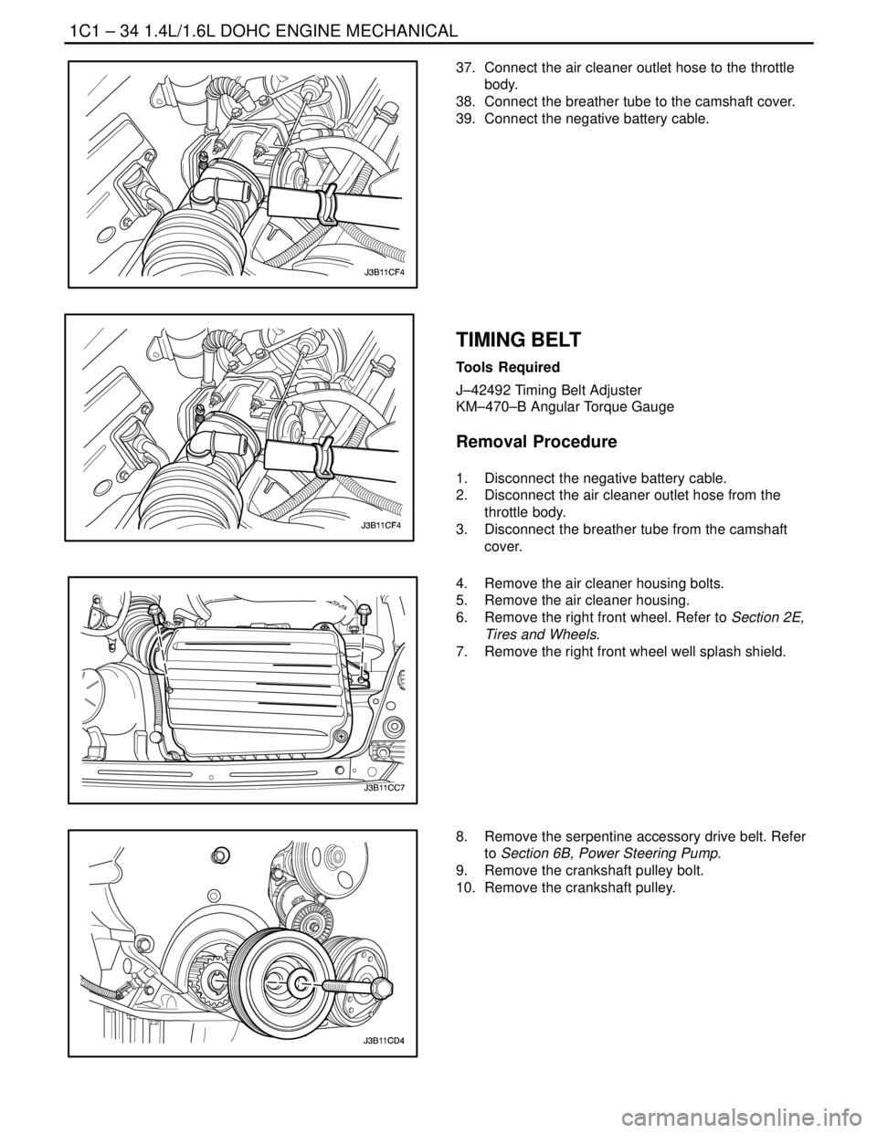
37. Connect the air cleaner outlet hose to the throttle
body.
38. Connect the breather tube to the camshaft cover.
39. Connect the negative battery cable.
TIMING BELT
Tools Required
J–42492 Timing Belt Adjuster
KM–470–B Angular Torque Gauge
Removal Procedure
1. Disconnect the negative battery cable.
2. Disconnect the air cleaner outlet hose from the
throttle body.
3. Disconnect the breather tube from the camshaft
cover.
4. Remove the air cleaner housing bolts.
5. Remove the air cleaner housing.
6. Remove the right front wheel. Refer to Section 2E,
Tires and Wheels.
7. Remove the right front wheel well splash shield.
8. Remove the serpentine accessory drive belt. Refer
to Section 6B, Power Steering Pump.
9. Remove the crankshaft pulley bolt.
10. Remove the crankshaft pulley.
Page 78 of 2643
1.4L/1.6L DOHC ENGINE MECHANICAL 1C1 – 35
DAEWOO V–121 BL4
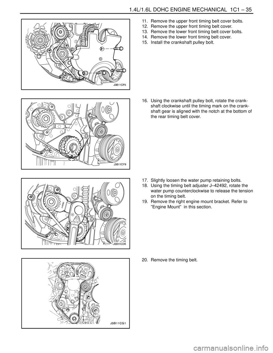
11. Remove the upper front timing belt cover bolts.
12. Remove the upper front timing belt cover.
13. Remove the lower front timing belt cover bolts.
14. Remove the lower front timing belt cover.
15. Install the crankshaft pulley bolt.
16. Using the crankshaft pulley bolt, rotate the crank-
shaft clockwise until the timing mark on the crank-
shaft gear is aligned with the notch at the bottom of
the rear timing belt cover.
17. Slightly loosen the water pump retaining bolts.
18. Using the timing belt adjuster J–42492, rotate the
water pump counterclockwise to release the tension
on the timing belt.
19. Remove the right engine mount bracket. Refer to
”Engine Mount” in this section.
20. Remove the timing belt.