Front DAEWOO LACETTI 2004 Service Owner's Guide
[x] Cancel search | Manufacturer: DAEWOO, Model Year: 2004, Model line: LACETTI, Model: DAEWOO LACETTI 2004Pages: 2643, PDF Size: 80.54 MB
Page 109 of 2643
1C1 – 66I1.4L/1.6L DOHC ENGINE MECHANICAL
DAEWOO V–121 BL4
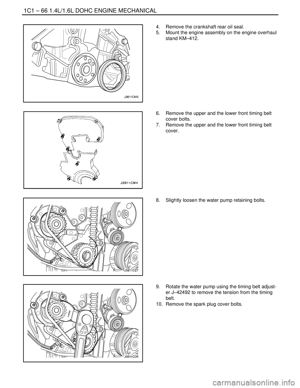
4. Remove the crankshaft rear oil seal.
5. Mount the engine assembly on the engine overhaul
stand KM–412.
6. Remove the upper and the lower front timing belt
cover bolts.
7. Remove the upper and the lower front timing belt
cover.
8. Slightly loosen the water pump retaining bolts.
9. Rotate the water pump using the timing belt adjust-
er J–42492 to remove the tension from the timing
belt.
10. Remove the spark plug cover bolts.
Page 112 of 2643
1.4L/1.6L DOHC ENGINE MECHANICAL 1C1 – 69
DAEWOO V–121 BL4
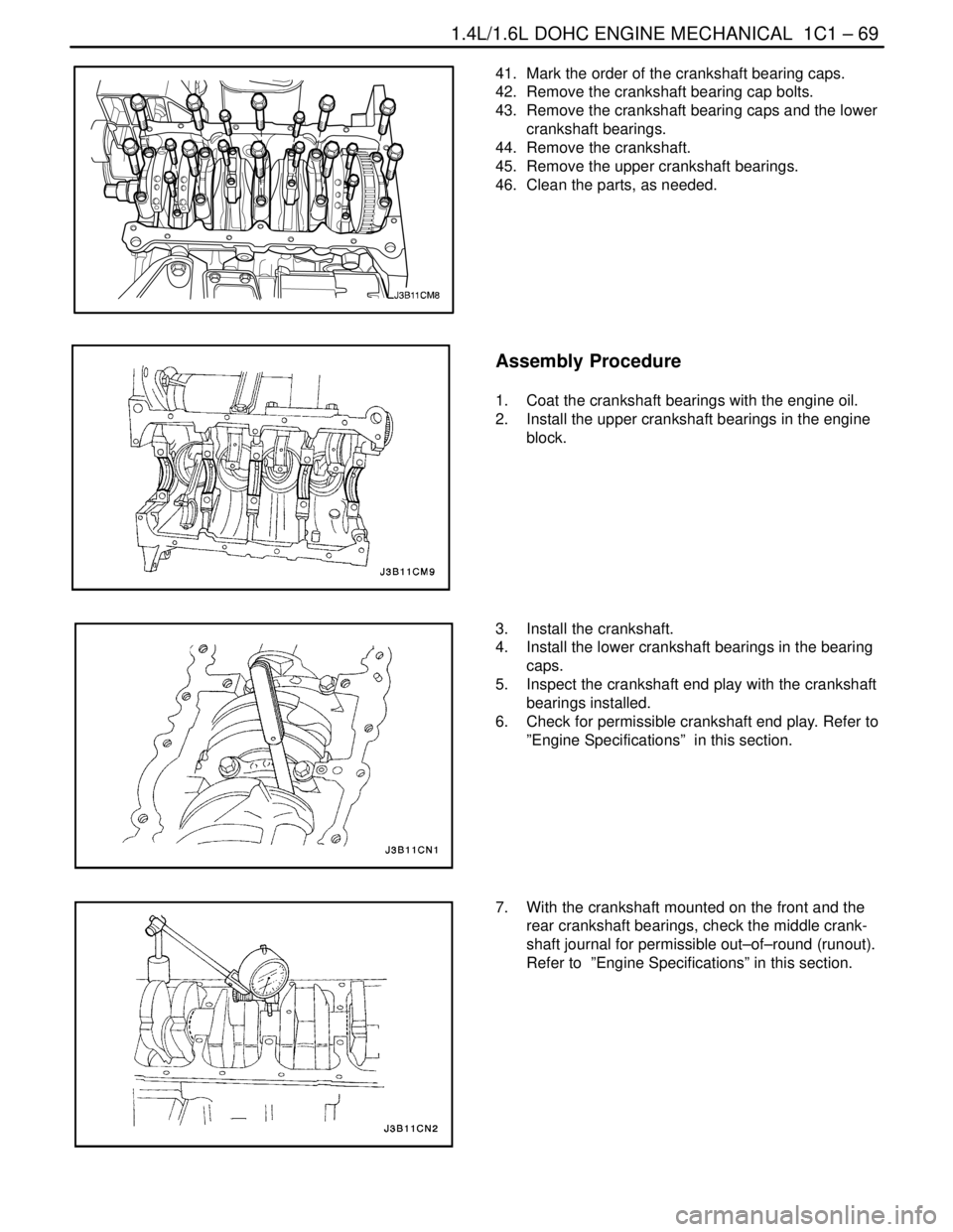
41. Mark the order of the crankshaft bearing caps.
42. Remove the crankshaft bearing cap bolts.
43. Remove the crankshaft bearing caps and the lower
crankshaft bearings.
44. Remove the crankshaft.
45. Remove the upper crankshaft bearings.
46. Clean the parts, as needed.
Assembly Procedure
1. Coat the crankshaft bearings with the engine oil.
2. Install the upper crankshaft bearings in the engine
block.
3. Install the crankshaft.
4. Install the lower crankshaft bearings in the bearing
caps.
5. Inspect the crankshaft end play with the crankshaft
bearings installed.
6. Check for permissible crankshaft end play. Refer to
”Engine Specifications” in this section.
7. With the crankshaft mounted on the front and the
rear crankshaft bearings, check the middle crank-
shaft journal for permissible out–of–round (runout).
Refer to ”Engine Specifications” in this section.
Page 116 of 2643
1.4L/1.6L DOHC ENGINE MECHANICAL 1C1 – 73
DAEWOO V–121 BL4
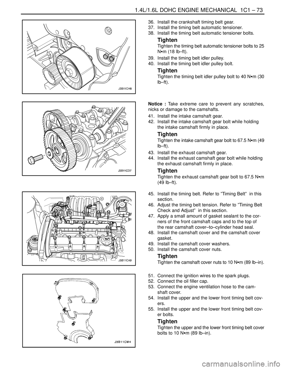
36. Install the crankshaft timing belt gear.
37. Install the timing belt automatic tensioner.
38. Install the timing belt automatic tensioner bolts.
Tighten
Tighten the timing belt automatic tensioner bolts to 25
NSm (18 lb–ft).
39. Install the timing belt idler pulley.
40. Install the timing belt idler pulley bolt.
Tighten
Tighten the timing belt idler pulley bolt to 40 NSm (30
lb–ft).
Notice : Take extreme care to prevent any scratches,
nicks or damage to the camshafts.
41. Install the intake camshaft gear.
42. Install the intake camshaft gear bolt while holding
the intake camshaft firmly in place.
Tighten
Tighten the intake camshaft gear bolt to 67.5 NSm (49
lb–ft).
43. Install the exhaust camshaft gear.
44. Install the exhaust camshaft gear bolt while holding
the exhaust camshaft firmly in place.
Tighten
Tighten the exhaust camshaft gear bolt to 67.5 NSm
(49 lb–ft).
45. Install the timing belt. Refer to ”Timing Belt” in this
section.
46. Adjust the timing belt tension. Refer to ”Timing Belt
Check and Adjust” in this section.
47. Apply a small amount of gasket sealant to the cor-
ners of the front camshaft caps and to the top of
the rear camshaft cover–to–cylinder head seal.
48. Install the camshaft cover and the camshaft cover
gasket.
49. Install the camshaft cover washers.
50. Install the camshaft cover nuts.
Tighten
Tighten the camshaft cover nuts to 10 NSm (89 lb–in).
51. Connect the ignition wires to the spark plugs.
52. Connect the oil filler cap.
53. Connect the engine ventilation hose to the cam-
shaft cover.
54. Install the upper and the lower front timing belt cov-
ers.
55. Install the upper and the lower front timing belt cov-
er bolts.
Tighten
Tighten the upper and the lower front timing belt cover
bolts to 10 NSm (89 lb–in).
Page 118 of 2643
1.4L/1.6L DOHC ENGINE MECHANICAL 1C1 – 75
DAEWOO V–121 BL4
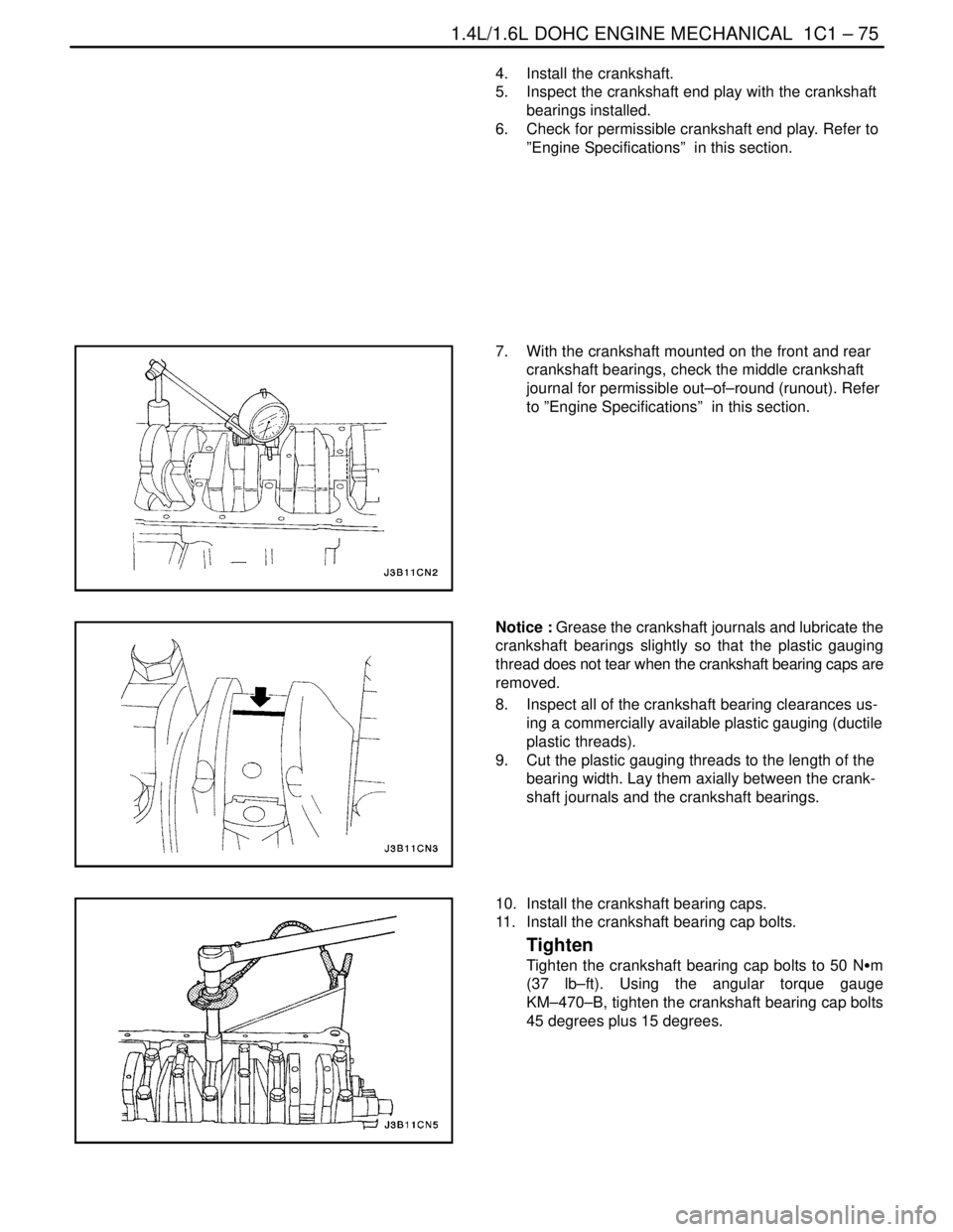
4. Install the crankshaft.
5. Inspect the crankshaft end play with the crankshaft
bearings installed.
6. Check for permissible crankshaft end play. Refer to
”Engine Specifications” in this section.
7. With the crankshaft mounted on the front and rear
crankshaft bearings, check the middle crankshaft
journal for permissible out–of–round (runout). Refer
to ”Engine Specifications” in this section.
Notice : Grease the crankshaft journals and lubricate the
crankshaft bearings slightly so that the plastic gauging
thread does not tear when the crankshaft bearing caps are
removed.
8. Inspect all of the crankshaft bearing clearances us-
ing a commercially available plastic gauging (ductile
plastic threads).
9. Cut the plastic gauging threads to the length of the
bearing width. Lay them axially between the crank-
shaft journals and the crankshaft bearings.
10. Install the crankshaft bearing caps.
11. Install the crankshaft bearing cap bolts.
Tighten
Tighten the crankshaft bearing cap bolts to 50 NSm
(37 lb–ft). Using the angular torque gauge
KM–470–B, tighten the crankshaft bearing cap bolts
45 degrees plus 15 degrees.
Page 124 of 2643

1C2 – 4I1.8L DOHC ENGINE MECHANICAL
DAEWOO V–121 BL4
FASTENER TIGHTENING SPECIFCATIONS
ApplicationNSmLb–FtLb–In
Air Cleaner Housing Bolts10–89
Automatic Tensioner Bolt2518–
Camshaft Bearing Bridge and Oil Pan Scraper Bolts20 + 45°15 + 45°–
Camshaft Bearing Cap Bolts8–71
Camshaft Cover Bolts8–71
Charcoal Canister Purge and Exhaust Gas Recirculation Sole-
noid Bracket Bolt5–44
Connecting Rod Bearing Cap Bolts35
+ 45° + 15°26
+ 45° + 15°–
Coolant Bypass Housing and Mounting Bolts1511–
Crankshaft Bearing Cap Bolts50
+ 45° + 15°37
+ 45° + 15°–
Crankshaft Pulley Bolts2015–
Crankshaft Gear Bolt145
+ 30° + 15°107
+ 30° + 15°–
Cylinder Head Bolts25 + 90°
+ 90° + 90°18 + 90°
+ 90° + 90°–
Direct Ignition System Coil and Exhaust Gas Recirculation
Mounting Bracket Bolts2518–
Engine Mount Bracket Retaining Bolts and Nuts5541–
Engine Mount Retaining Bolts4533–
Engine–to–Intake Manifold Support Bracket Bolts2015–
Exhaust Camshaft Gear Bolt50
+ 60° + 15°37
+ 60° + 15°–
Exhaust Flex Pipe–to–Catalytic Converter or Connecting Pipe
Retaining Nuts3526–
Exhaust Flex Pipe–to–Exhaust Manifold Retaining Nuts3526–
Exhaust Manifold Heat Shield Bolts8–71
Exhaust Manifold Retaining Nuts2216–
Flexible Plate Bolts4533–
Flywheel Bolts65
+ 30° + 15°48
+ 30° + 15°–
Front Timing Belt Cover Bolts6–53
Generator–to–Intake Manifold Strap Bracket Bolt2216–
Generator–to–Intake Manifold Support Bracket Bolts3727–
Intake Camshaft Gear Bolt50
+ 60° + 15°37
+ 60° + 15°–
Intake Manifold Retaining Bolt and Nuts2216–
Intake Manifold Support Bracket Lower Bolt2518–
Intake Manifold Support Bracket Upper Bolts2518–
Lower Block Support Bracket and Splash Shield Bolts3526–
Oil Pan Drain Plug3526–
Oil Pan Flange–to–Transaxle Bolts4030–
Page 129 of 2643

1.8L DOHC ENGINE MECHANICAL 1C2 – 9
DAEWOO V–121 BL4
1. Bolt
2. Spark Plug Cover
3. Oil Filler Cap
4. Oil Filler Cap Seal
5. Bolt
6. Camshaft Cover
7. Camshaft Cover Gasket
8. Tappet Adjuster
9. Valve Key
10. Valve Spring Cap
11. Valve Spring
12. Valve Stem Seal
13. Valve Spring Seat
14. Valve Guide
15. Intake Valve Seat Ring
16. Exhaust Valve Seat Ring
17. Intake Valve
18. Exhaust Valve
19. Bolt
20. Front Camshaft Cap
21. Head Bolt
22. Bolt
23. Intermediate Camshaft Cap
24. Exhaust Gas Recirculation Adapter
25. Exhaust Gas Recirculation Adapter Gasket
26. Cylinder Head
27. Exhaust Manifold Gasket28. Exhaust Manifold
29. Nut
30. Exhaust Manifold Heat Shield
31. Cylinder Head Gasket
32. Bolt
33. Thermostat Housing
34. Thermostat Housing Gasket
35. Stud
36. Sleeve
37. Plug
38. Bolt
39. Camshaft Position Sensor
40. Oil Gallery Plug
41. Exhaust Camshaft
42. Seal Ring
43. Camshaft Gear
44. Washer
45. Camshaft Gear Bolt
46. Intake Camshaft
47. Intake Manifold Gasket
48. Intake Manifold
49. Throttle Body Gasket
50. Throttle Body
51. Nut
52. Charcoal Canister Purge Solenoid
53. Exhaust Gas Recirculation Solenoid
Page 131 of 2643

1.8L DOHC ENGINE MECHANICAL 1C2 – 11
DAEWOO V–121 BL4
1. Connecting Rod
2. Bearing Set
3. Connecting Rod Bolt
4. Piston Ring Set
5. Piston Pin
6. Piston
7. Engine Block
8. Sleeve
9. Water Jacket Cap
10. Bolt (Manual Transaxle)
11. Flywheel (Manual Transaxle)
12. Flexible Plate (Automatic Transaxle)
13. Bolt (Automatic Transaxle)
14. Clamp
15. Hose
16. Clamp
17. Engine Ventilation Pipe
18. Bolt
19. Gasket
20. Needle Sleeve
21. Crankshaft Rear Seal
22. Crankshaft
23. Transmitter Disk
24. Bolt
25. Oil Pan Scraper
26. Oil Pan
27. Drain Plug
28. Washer
29. Bolt
30. Sleeve
31. Gasket
32. Bolt
33. Oil Pump Cover
34. Ring Gear
35. Gear
36. Oil Pressure Switch
37. Washer
38. Washer
39. Oil Duct Outlet Plug
40. Connecting Piece
41. Seal Ring
42. Oil Filter43. Bypass Valve
44. Pressure Relief Valve Plunger
45. Pressure Relief Valve Spring
46. Seal Ring
47. Pressure Relief Valve Plug
48. Seal Ring
49. Bolt
50. Oil Suction Pipe
51. Bolt
52. Rear Timing Belt Cover
53. Bolt
54. Special Bolt
55. Idler Pulley
56. Stud
57. Nut
58. Bolt
59. Tensioner
60. Bolt
61. Thrust Inner Washer
62. Woodruff Key
63. Crankshaft Gear
64. Thrust Outer Washer
65. Bolt
66. Camshaft Drive Belt
67. Gasket
68. Front Timing Belt Cover
69. Bolt
70. Bushing Plug
71. Bushing
72. Oil Gallery Plug
73. Bolt
74. Water Pump
75. Seal Ring
76. Crankshaft Position Sensor
77. Bolt
78. Knock Sensor*
79. Bolt
80. Bolt
81. Crankshaft Bearing Bridge
* : 2.0L DOHC Engine
Page 133 of 2643
1.8L DOHC ENGINE MECHANICAL 1C2 – 13
DAEWOO V–121 BL4
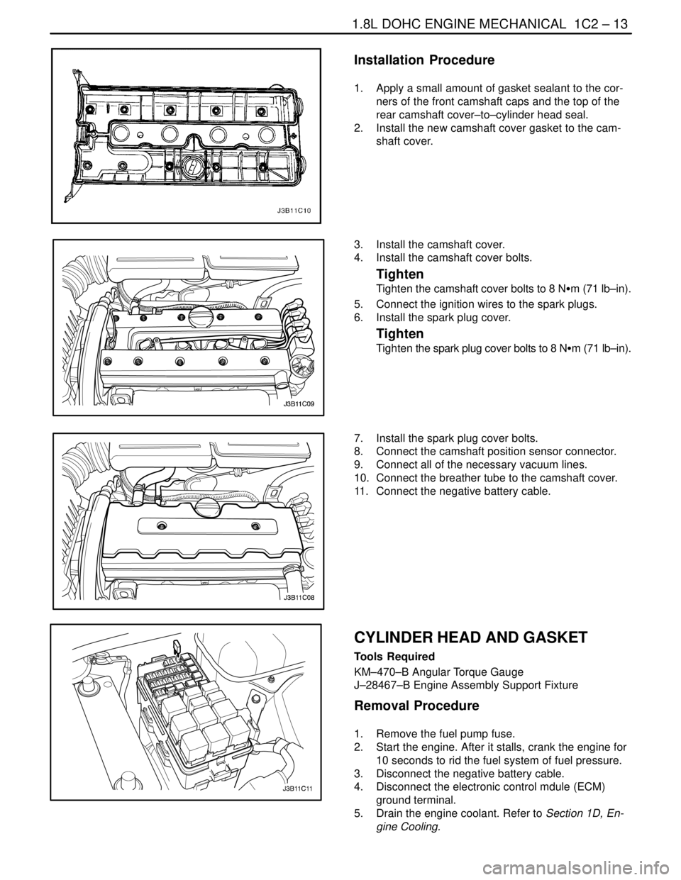
Installation Procedure
1. Apply a small amount of gasket sealant to the cor-
ners of the front camshaft caps and the top of the
rear camshaft cover–to–cylinder head seal.
2. Install the new camshaft cover gasket to the cam-
shaft cover.
3. Install the camshaft cover.
4. Install the camshaft cover bolts.
Tighten
Tighten the camshaft cover bolts to 8 NSm (71 lb–in).
5. Connect the ignition wires to the spark plugs.
6. Install the spark plug cover.
Tighten
Tighten the spark plug cover bolts to 8 NSm (71 lb–in).
7. Install the spark plug cover bolts.
8. Connect the camshaft position sensor connector.
9. Connect all of the necessary vacuum lines.
10. Connect the breather tube to the camshaft cover.
11. Connect the negative battery cable.
CYLINDER HEAD AND GASKET
Tools Required
KM–470–B Angular Torque Gauge
J–28467–B Engine Assembly Support Fixture
Removal Procedure
1. Remove the fuel pump fuse.
2. Start the engine. After it stalls, crank the engine for
10 seconds to rid the fuel system of fuel pressure.
3. Disconnect the negative battery cable.
4. Disconnect the electronic control mdule (ECM)
ground terminal.
5. Drain the engine coolant. Refer to Section 1D, En-
gine Cooling.
Page 134 of 2643
1C2 – 14I1.8L DOHC ENGINE MECHANICAL
DAEWOO V–121 BL4
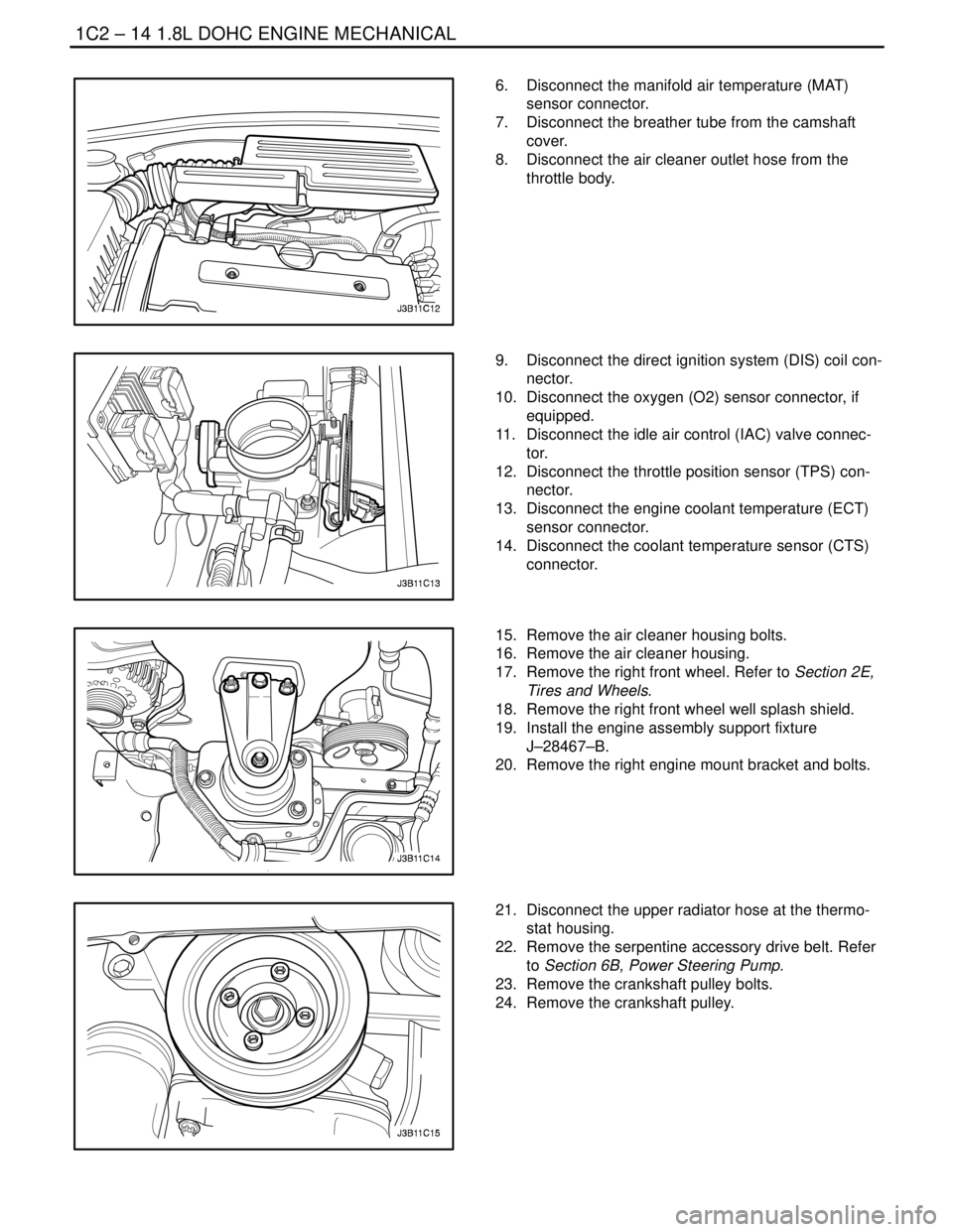
6. Disconnect the manifold air temperature (MAT)
sensor connector.
7. Disconnect the breather tube from the camshaft
cover.
8. Disconnect the air cleaner outlet hose from the
throttle body.
9. Disconnect the direct ignition system (DIS) coil con-
nector.
10. Disconnect the oxygen (O2) sensor connector, if
equipped.
11. Disconnect the idle air control (IAC) valve connec-
tor.
12. Disconnect the throttle position sensor (TPS) con-
nector.
13. Disconnect the engine coolant temperature (ECT)
sensor connector.
14. Disconnect the coolant temperature sensor (CTS)
connector.
15. Remove the air cleaner housing bolts.
16. Remove the air cleaner housing.
17. Remove the right front wheel. Refer to Section 2E,
Tires and Wheels.
18. Remove the right front wheel well splash shield.
19. Install the engine assembly support fixture
J–28467–B.
20. Remove the right engine mount bracket and bolts.
21. Disconnect the upper radiator hose at the thermo-
stat housing.
22. Remove the serpentine accessory drive belt. Refer
to Section 6B, Power Steering Pump.
23. Remove the crankshaft pulley bolts.
24. Remove the crankshaft pulley.
Page 135 of 2643
1.8L DOHC ENGINE MECHANICAL 1C2 – 15
DAEWOO V–121 BL4
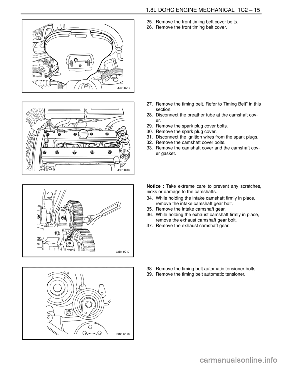
25. Remove the front timing belt cover bolts.
26. Remove the front timing belt cover.
27. Remove the timing belt. Refer to Timing Belt” in this
section.
28. Disconnect the breather tube at the camshaft cov-
er.
29. Remove the spark plug cover bolts.
30. Remove the spark plug cover.
31. Disconnect the ignition wires from the spark plugs.
32. Remove the camshaft cover bolts.
33. Remove the camshaft cover and the camshaft cov-
er gasket.
Notice : Take extreme care to prevent any scratches,
nicks or damage to the camshafts.
34. While holding the intake camshaft firmly in place,
remove the intake camshaft gear bolt.
35. Remove the intake camshaft gear.
36. While holding the exhaust camshaft firmly in place,
remove the exhaust camshaft gear bolt.
37. Remove the exhaust camshaft gear.
38. Remove the timing belt automatic tensioner bolts.
39. Remove the timing belt automatic tensioner.