light DAEWOO LACETTI 2004 Service User Guide
[x] Cancel search | Manufacturer: DAEWOO, Model Year: 2004, Model line: LACETTI, Model: DAEWOO LACETTI 2004Pages: 2643, PDF Size: 80.54 MB
Page 78 of 2643
1.4L/1.6L DOHC ENGINE MECHANICAL 1C1 – 35
DAEWOO V–121 BL4
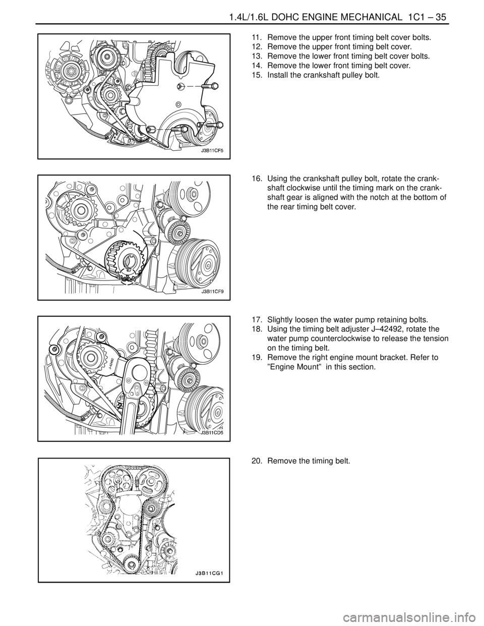
11. Remove the upper front timing belt cover bolts.
12. Remove the upper front timing belt cover.
13. Remove the lower front timing belt cover bolts.
14. Remove the lower front timing belt cover.
15. Install the crankshaft pulley bolt.
16. Using the crankshaft pulley bolt, rotate the crank-
shaft clockwise until the timing mark on the crank-
shaft gear is aligned with the notch at the bottom of
the rear timing belt cover.
17. Slightly loosen the water pump retaining bolts.
18. Using the timing belt adjuster J–42492, rotate the
water pump counterclockwise to release the tension
on the timing belt.
19. Remove the right engine mount bracket. Refer to
”Engine Mount” in this section.
20. Remove the timing belt.
Page 98 of 2643
1.4L/1.6L DOHC ENGINE MECHANICAL 1C1 – 55
DAEWOO V–121 BL4
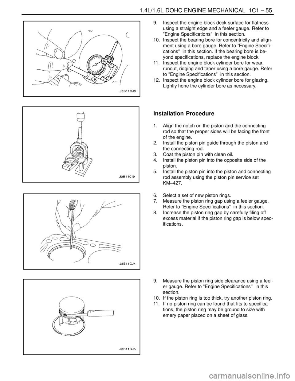
9. Inspect the engine block deck surface for flatness
using a straight edge and a feeler gauge. Refer to
”Engine Specifications” in this section.
10. Inspect the bearing bore for concentricity and align-
ment using a bore gauge. Refer to ”Engine Specifi-
cations” in this section. If the bearing bore is be-
yond specifications, replace the engine block.
11. Inspect the engine block cylinder bore for wear,
runout, ridging and taper using a bore gauge. Refer
to ”Engine Specifications” in this section.
12. Inspect the engine block cylinder bore for glazing.
Lightly hone the cylinder bore as necessary.
Installation Procedure
1. Align the notch on the piston and the connecting
rod so that the proper sides will be facing the front
of the engine.
2. Install the piston pin guide through the piston and
the connecting rod.
3. Coat the piston pin with clean oil.
4. Install the piston pin into the opposite side of the
piston.
5. Install the piston pin into the piston and connecting
rod assembly using the piston pin service set
KM–427.
6. Select a set of new piston rings.
7. Measure the piston ring gap using a feeler gauge.
Refer to ”Engine Specifications” in this section.
8. Increase the piston ring gap by carefully filing off
excess material if the piston ring gap is below spec-
ifications.
9. Measure the piston ring side clearance using a feel-
er gauge. Refer to ”Engine Specifications’’ in this
section.
10. If the piston ring is too thick, try another piston ring.
11. If no piston ring can be found that fits to specifica-
tions, the piston ring may be ground to size with
emery paper placed on a sheet of glass.
Page 109 of 2643
1C1 – 66I1.4L/1.6L DOHC ENGINE MECHANICAL
DAEWOO V–121 BL4
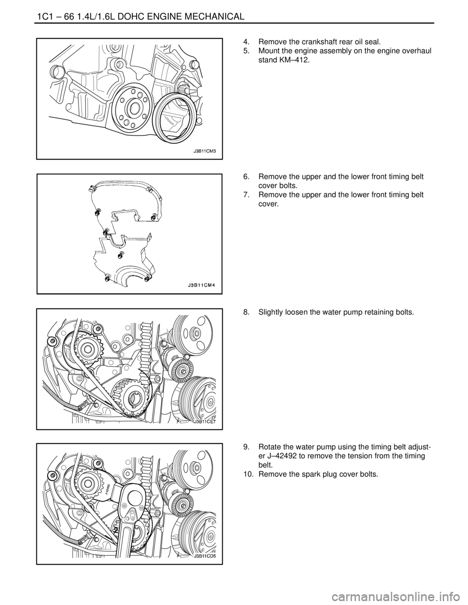
4. Remove the crankshaft rear oil seal.
5. Mount the engine assembly on the engine overhaul
stand KM–412.
6. Remove the upper and the lower front timing belt
cover bolts.
7. Remove the upper and the lower front timing belt
cover.
8. Slightly loosen the water pump retaining bolts.
9. Rotate the water pump using the timing belt adjust-
er J–42492 to remove the tension from the timing
belt.
10. Remove the spark plug cover bolts.
Page 113 of 2643
1C1 – 70I1.4L/1.6L DOHC ENGINE MECHANICAL
DAEWOO V–121 BL4
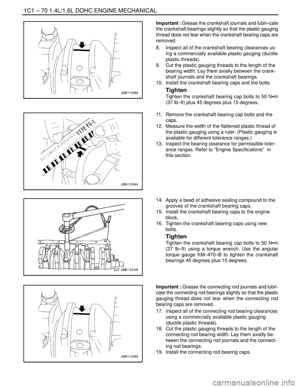
Important : Grease the crankshaft journals and lubri–cate
the crankshaft bearings slightly so that the plastic gauging
thread does not tear when the crankshaft bearing caps are
removed.
8. Inspect all of the crankshaft bearing clearances us-
ing a commercially available plastic gauging (ductile
plastic threads).
9. Cut the plastic gauging threads to the length of the
bearing width. Lay them axially between the crank-
shaft journals and the crankshaft bearings.
10. Install the crankshaft bearing caps and the bolts.
Tighten
Tighten the crankshaft bearing cap bolts to 50 NSm
(37 lb–ft) plus 45 degrees plus 15 degrees.
11. Remove the crankshaft bearing cap bolts and the
caps.
12. Measure the width of the flattened plastic thread of
the plastic gauging using a ruler. (Plastic gauging is
available for different tolerance ranges.)
13. Inspect the bearing clearance for permissible toler-
ance ranges. Refer to ”Engine Specifications” in
this section.
14. Apply a bead of adhesive sealing compound to the
grooves of the crankshaft bearing caps.
15. Install the crankshaft bearing caps to the engine
block.
16. Tighten the crankshaft bearing caps using new
bolts.
Tighten
Tighten the crankshaft bearing cap bolts to 50 NSm
(37 lb–ft) using a torque wrench. Use the angular
torque gauge KM–470–B to tighten the crankshaft
bearings 45 degrees plus 15 degrees.
Important : Grease the connecting rod journals and lubri-
cate the connecting rod bearings slightly so that the plastic
gauging thread does not tear when the connecting rod
bearing caps are removed.
17. Inspect all of the connecting rod bearing clearances
using a commercially available plastic gauging
(ductile plastic threads).
18. Cut the plastic gauging threads to the length of the
connecting rod bearing width. Lay them axially be-
tween the connecting rod journals and the connect-
ing rod bearings.
19. Install the connecting rod bearing caps.
Page 118 of 2643
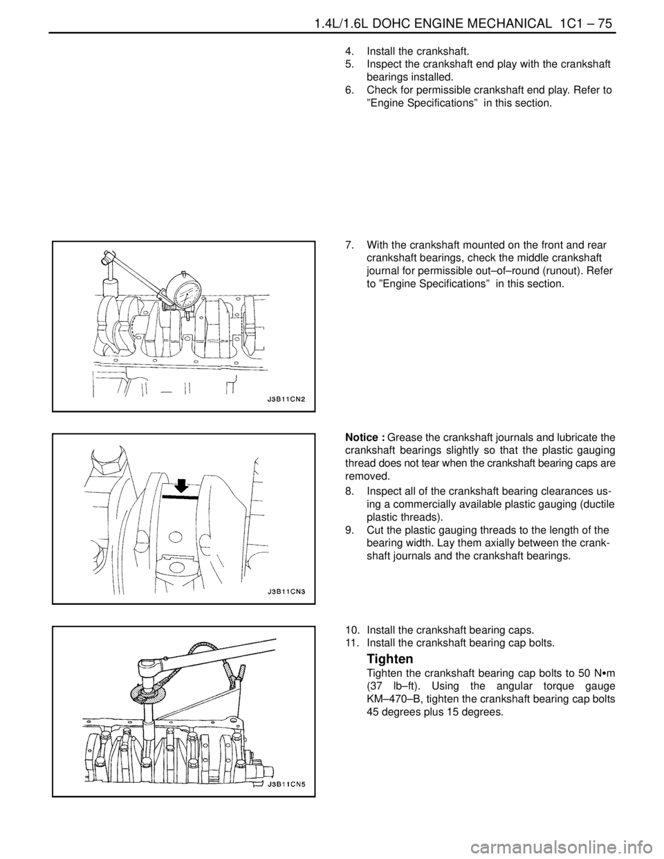
1.4L/1.6L DOHC ENGINE MECHANICAL 1C1 – 75
DAEWOO V–121 BL4
4. Install the crankshaft.
5. Inspect the crankshaft end play with the crankshaft
bearings installed.
6. Check for permissible crankshaft end play. Refer to
”Engine Specifications” in this section.
7. With the crankshaft mounted on the front and rear
crankshaft bearings, check the middle crankshaft
journal for permissible out–of–round (runout). Refer
to ”Engine Specifications” in this section.
Notice : Grease the crankshaft journals and lubricate the
crankshaft bearings slightly so that the plastic gauging
thread does not tear when the crankshaft bearing caps are
removed.
8. Inspect all of the crankshaft bearing clearances us-
ing a commercially available plastic gauging (ductile
plastic threads).
9. Cut the plastic gauging threads to the length of the
bearing width. Lay them axially between the crank-
shaft journals and the crankshaft bearings.
10. Install the crankshaft bearing caps.
11. Install the crankshaft bearing cap bolts.
Tighten
Tighten the crankshaft bearing cap bolts to 50 NSm
(37 lb–ft). Using the angular torque gauge
KM–470–B, tighten the crankshaft bearing cap bolts
45 degrees plus 15 degrees.
Page 119 of 2643
1C1 – 76I1.4L/1.6L DOHC ENGINE MECHANICAL
DAEWOO V–121 BL4
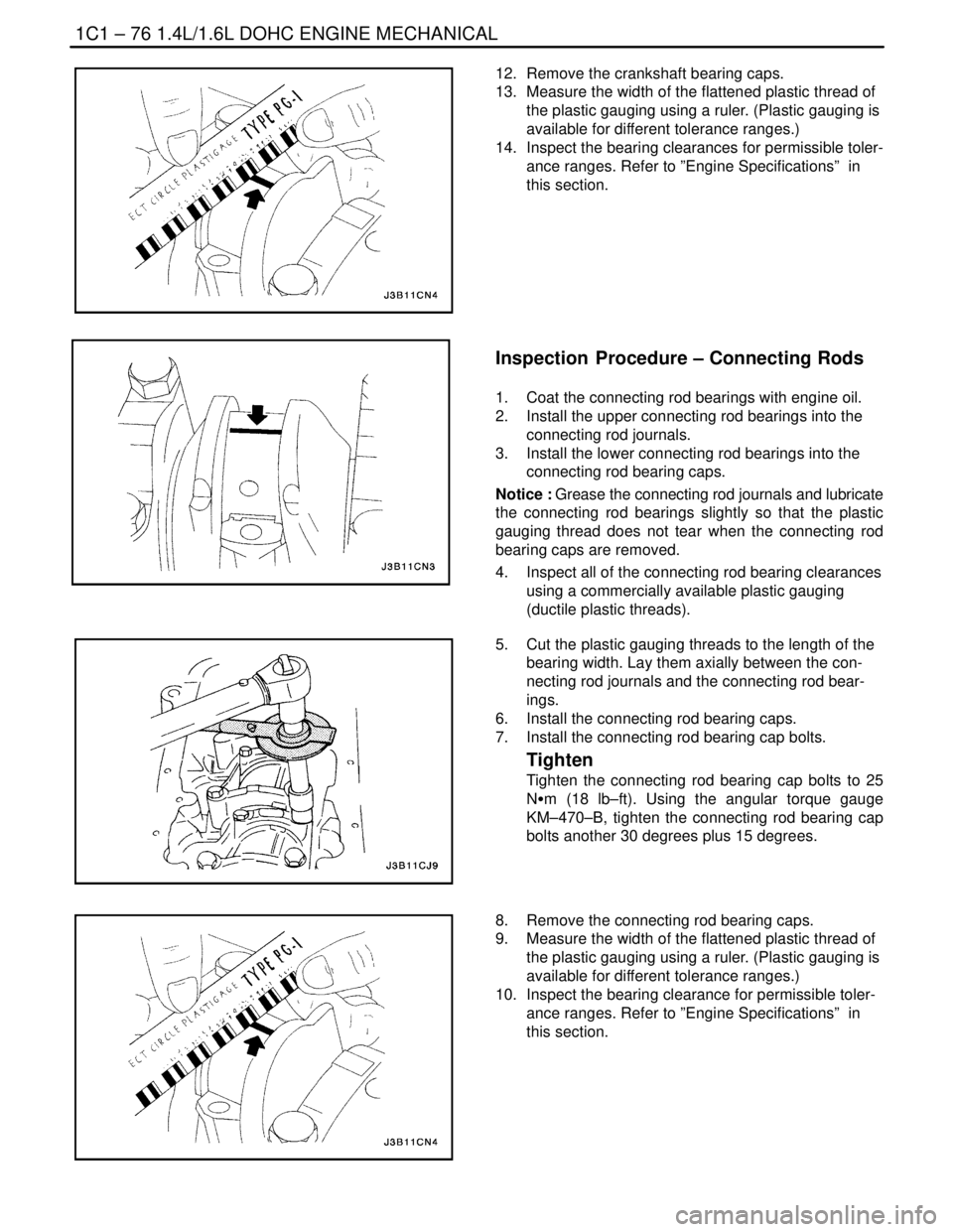
12. Remove the crankshaft bearing caps.
13. Measure the width of the flattened plastic thread of
the plastic gauging using a ruler. (Plastic gauging is
available for different tolerance ranges.)
14. Inspect the bearing clearances for permissible toler-
ance ranges. Refer to ”Engine Specifications” in
this section.
Inspection Procedure – Connecting Rods
1. Coat the connecting rod bearings with engine oil.
2. Install the upper connecting rod bearings into the
connecting rod journals.
3. Install the lower connecting rod bearings into the
connecting rod bearing caps.
Notice : Grease the connecting rod journals and lubricate
the connecting rod bearings slightly so that the plastic
gauging thread does not tear when the connecting rod
bearing caps are removed.
4. Inspect all of the connecting rod bearing clearances
using a commercially available plastic gauging
(ductile plastic threads).
5. Cut the plastic gauging threads to the length of the
bearing width. Lay them axially between the con-
necting rod journals and the connecting rod bear-
ings.
6. Install the connecting rod bearing caps.
7. Install the connecting rod bearing cap bolts.
Tighten
Tighten the connecting rod bearing cap bolts to 25
NSm (18 lb–ft). Using the angular torque gauge
KM–470–B, tighten the connecting rod bearing cap
bolts another 30 degrees plus 15 degrees.
8. Remove the connecting rod bearing caps.
9. Measure the width of the flattened plastic thread of
the plastic gauging using a ruler. (Plastic gauging is
available for different tolerance ranges.)
10. Inspect the bearing clearance for permissible toler-
ance ranges. Refer to ”Engine Specifications” in
this section.
Page 173 of 2643
1.8L DOHC ENGINE MECHANICAL 1C2 – 53
DAEWOO V–121 BL4
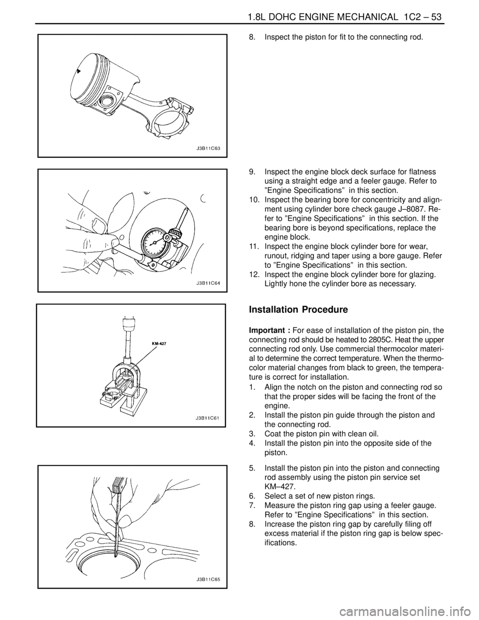
8. Inspect the piston for fit to the connecting rod.
9. Inspect the engine block deck surface for flatness
using a straight edge and a feeler gauge. Refer to
”Engine Specifications” in this section.
10. Inspect the bearing bore for concentricity and align-
ment using cylinder bore check gauge J–8087. Re-
fer to ”Engine Specifications” in this section. If the
bearing bore is beyond specifications, replace the
engine block.
11. Inspect the engine block cylinder bore for wear,
runout, ridging and taper using a bore gauge. Refer
to ”Engine Specifications” in this section.
12. Inspect the engine block cylinder bore for glazing.
Lightly hone the cylinder bore as necessary.
Installation Procedure
Important : For ease of installation of the piston pin, the
connecting rod should be heated to 2805C. Heat the upper
connecting rod only. Use commercial thermocolor materi-
al to determine the correct temperature. When the thermo-
color material changes from black to green, the tempera-
ture is correct for installation.
1. Align the notch on the piston and connecting rod so
that the proper sides will be facing the front of the
engine.
2. Install the piston pin guide through the piston and
the connecting rod.
3. Coat the piston pin with clean oil.
4. Install the piston pin into the opposite side of the
piston.
5. Install the piston pin into the piston and connecting
rod assembly using the piston pin service set
KM–427.
6. Select a set of new piston rings.
7. Measure the piston ring gap using a feeler gauge.
Refer to ”Engine Specifications” in this section.
8. Increase the piston ring gap by carefully filing off
excess material if the piston ring gap is below spec-
ifications.
Page 181 of 2643
1.8L DOHC ENGINE MECHANICAL 1C2 – 61
DAEWOO V–121 BL4
4. Inspect the dimension for the valve seat width.
S Intake: 1.2 to 1.4 mm (0.047 to 0.055 inch).
S Exhaust: 1.4 to 1.8 mm (0.055 to 0.070 inch).
5. Inspect the assembly height of the intake valves
and the exhaust valves. If the dimension is exceed-
ed, install new valves. Inspect the assembly height
of the intake valves and the exhaust valves again. If
the valve assembly height is still too large despite
replacing the valves, replace the cylinder head.
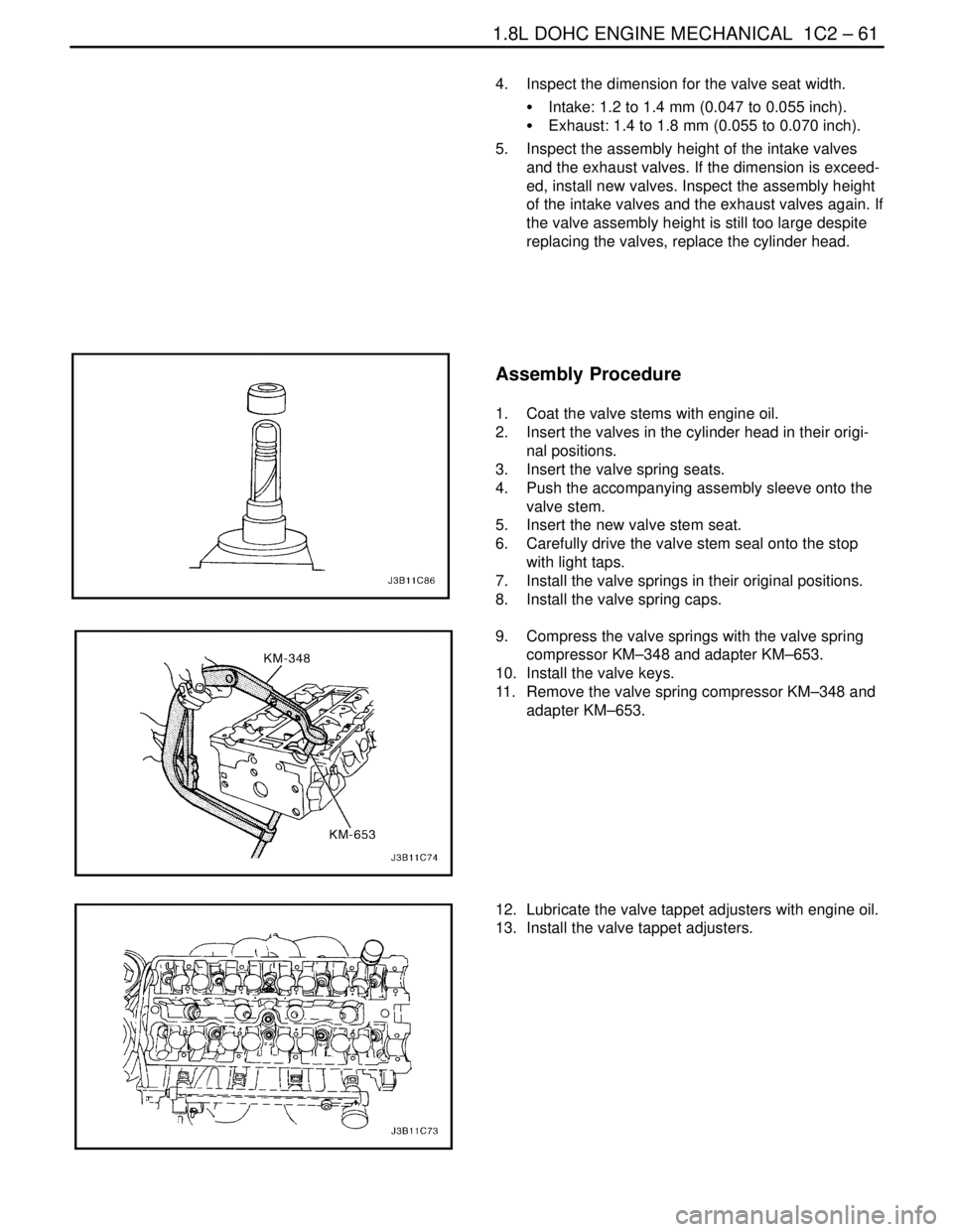
Assembly Procedure
1. Coat the valve stems with engine oil.
2. Insert the valves in the cylinder head in their origi-
nal positions.
3. Insert the valve spring seats.
4. Push the accompanying assembly sleeve onto the
valve stem.
5. Insert the new valve stem seat.
6. Carefully drive the valve stem seal onto the stop
with light taps.
7. Install the valve springs in their original positions.
8. Install the valve spring caps.
9. Compress the valve springs with the valve spring
compressor KM–348 and adapter KM–653.
10. Install the valve keys.
11. Remove the valve spring compressor KM–348 and
adapter KM–653.
12. Lubricate the valve tappet adjusters with engine oil.
13. Install the valve tappet adjusters.
Page 187 of 2643
1.8L DOHC ENGINE MECHANICAL 1C2 – 67
DAEWOO V–121 BL4
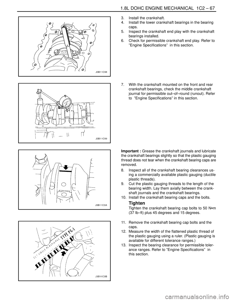
3. Install the crankshaft.
4. Install the lower crankshaft bearings in the bearing
caps.
5. Inspect the crankshaft end play with the crankshaft
bearings installed.
6. Check for permissible crankshaft end play. Refer to
”Engine Specifications” in this section.
7. With the crankshaft mounted on the front and rear
crankshaft bearings, check the middle crankshaft
journal for permissible out–of–round (runout). Refer
to ”Engine Specifications” in this section.
Important : Grease the crankshaft journals and lubricate
the crankshaft bearings slightly so that the plastic gauging
thread does not tear when the crankshaft bearing caps are
removed.
8. Inspect all of the crankshaft bearing clearances us-
ing a commercially available plastic gauging (ductile
plastic threads).
9. Cut the plastic gauging threads to the length of the
bearing width. Lay them axially between the crank-
shaft journals and the crankshaft bearings.
10. Install the crankshaft bearing caps and the bolts.
Tighten
Tighten the crankshaft bearing cap bolts to 50 NSm
(37 lb–ft) plus 45 degrees and 15 degrees.
11. Remove the crankshaft bearing cap bolts and the
caps.
12. Measure the width of the flattened plastic thread of
the plastic gauging using a ruler. (Plastic gauging is
available for different tolerance ranges.)
13. Inspect the bearing clearance for permissible toler-
ance ranges. Refer to ”Engine Specifications” in
this section.
Page 188 of 2643
1C2 – 68I1.8L DOHC ENGINE MECHANICAL
DAEWOO V–121 BL4
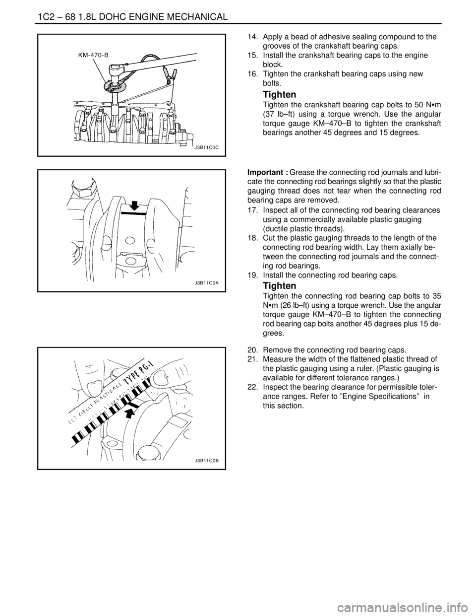
14. Apply a bead of adhesive sealing compound to the
grooves of the crankshaft bearing caps.
15. Install the crankshaft bearing caps to the engine
block.
16. Tighten the crankshaft bearing caps using new
bolts.
Tighten
Tighten the crankshaft bearing cap bolts to 50 NSm
(37 lb–ft) using a torque wrench. Use the angular
torque gauge KM–470–B to tighten the crankshaft
bearings another 45 degrees and 15 degrees.
Important : Grease the connecting rod journals and lubri-
cate the connecting rod bearings slightly so that the plastic
gauging thread does not tear when the connecting rod
bearing caps are removed.
17. Inspect all of the connecting rod bearing clearances
using a commercially available plastic gauging
(ductile plastic threads).
18. Cut the plastic gauging threads to the length of the
connecting rod bearing width. Lay them axially be-
tween the connecting rod journals and the connect-
ing rod bearings.
19. Install the connecting rod bearing caps.
Tighten
Tighten the connecting rod bearing cap bolts to 35
NSm (26 lb–ft) using a torque wrench. Use the angular
torque gauge KM–470–B to tighten the connecting
rod bearing cap bolts another 45 degrees plus 15 de-
grees.
20. Remove the connecting rod bearing caps.
21. Measure the width of the flattened plastic thread of
the plastic gauging using a ruler. (Plastic gauging is
available for different tolerance ranges.)
22. Inspect the bearing clearance for permissible toler-
ance ranges. Refer to ”Engine Specifications” in
this section.