window DAEWOO LACETTI 2004 Service User Guide
[x] Cancel search | Manufacturer: DAEWOO, Model Year: 2004, Model line: LACETTI, Model: DAEWOO LACETTI 2004Pages: 2643, PDF Size: 80.54 MB
Page 1990 of 2643
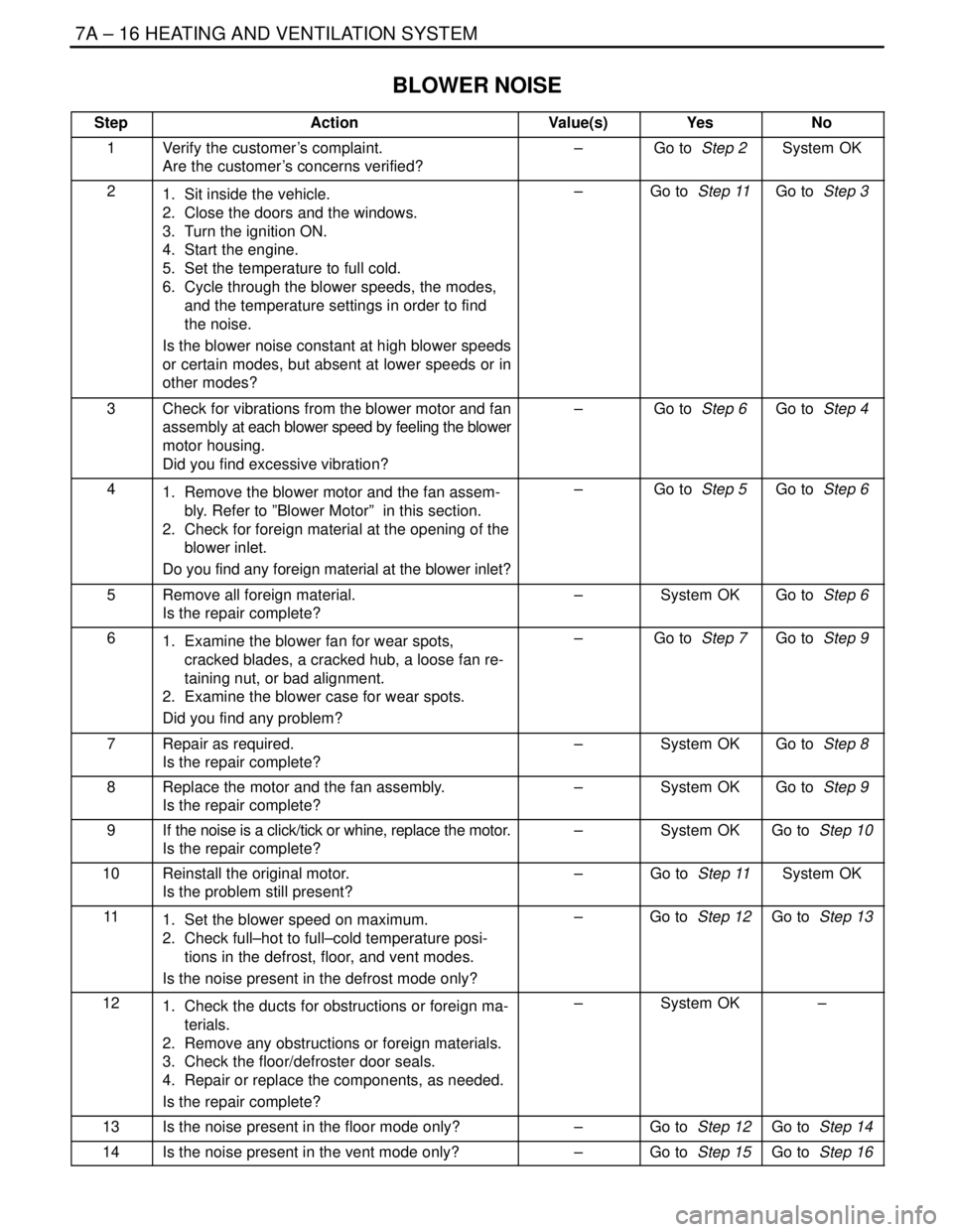
7A – 16IHEATING AND VENTILATION SYSTEM
DAEWOO V–121 BL4
BLOWER NOISE
StepActionValue(s)YesNo
1Verify the customer’s complaint.
Are the customer’s concerns verified?–Go to Step 2System OK
21. Sit inside the vehicle.
2. Close the doors and the windows.
3. Turn the ignition ON.
4. Start the engine.
5. Set the temperature to full cold.
6. Cycle through the blower speeds, the modes,
and the temperature settings in order to find
the noise.
Is the blower noise constant at high blower speeds
or certain modes, but absent at lower speeds or in
other modes?–Go to Step 11Go to Step 3
3Check for vibrations from the blower motor and fan
assembly at each blower speed by feeling the blower
motor housing.
Did you find excessive vibration?–Go to Step 6Go to Step 4
41. Remove the blower motor and the fan assem-
bly. Refer to ”Blower Motor” in this section.
2. Check for foreign material at the opening of the
blower inlet.
Do you find any foreign material at the blower inlet?–Go to Step 5Go to Step 6
5Remove all foreign material.
Is the repair complete?–System OKGo to Step 6
61. Examine the blower fan for wear spots,
cracked blades, a cracked hub, a loose fan re-
taining nut, or bad alignment.
2. Examine the blower case for wear spots.
Did you find any problem?–Go to Step 7Go to Step 9
7Repair as required.
Is the repair complete?–System OKGo to Step 8
8Replace the motor and the fan assembly.
Is the repair complete?–System OKGo to Step 9
9If the noise is a click/tick or whine, replace the motor.
Is the repair complete?–System OKGo to Step 10
10Reinstall the original motor.
Is the problem still present?–Go to Step 11System OK
111. Set the blower speed on maximum.
2. Check full–hot to full–cold temperature posi-
tions in the defrost, floor, and vent modes.
Is the noise present in the defrost mode only?–Go to Step 12Go to Step 13
121. Check the ducts for obstructions or foreign ma-
terials.
2. Remove any obstructions or foreign materials.
3. Check the floor/defroster door seals.
4. Repair or replace the components, as needed.
Is the repair complete?–System OK–
13Is the noise present in the floor mode only?–Go to Step 12Go to Step 14
14Is the noise present in the vent mode only?–Go to Step 15Go to Step 16
Page 2002 of 2643
7A – 28IHEATING AND VENTILATION SYSTEM
DAEWOO V–121 BL4
GENERAL DESCRIPTION
AND SYSTEM OPERATION
HEATING AND VENTILATION
SYSTEMS
The base heater system is designed to provide heating,
ventilation, windshield defrosting, side window defogging,
and on some vehicles, heating directly to the rear seat
area.
The heater and fan assembly blower regulates the airflow
from the air inlet for further processing and distribution.
The heater core transfers the heat from the engine coolant
to the inlet air.
The temperature door regulates the amount of the air that
passes through the heater core. The temperature door
also controls the temperature of the air by controlling the
mix of the heated air and the ambient air.
The mode door regulates the flow and the distribution of
the processed air to the heater ducts and to the defroster
ducts.
This console–mounted heating and ventilation panel con-
tains the following:
The Rotary Temperature Control Knob
1. The Rotary Temperature Control Knob
S Actuates by cable.
S Raises the temperature of the air entering the
vehicle by rotation toward the right, or the red
portion of the knob.
2. The Rotary Blower Control Knob
S Turns ON to operate the blower motor at four
speeds.
S Turns OFF to stop the blower.
S Operates completely independently both from
the mode control that regulates the defroster
door and from the temperature control knob.S Changes the fan speed in any mode and at any
temperature setting.
3. The Rotary Mode Control Knob
S Actuates by cable.
S Regulates the air distribution between the wind-
shield, the instrument panel, and the floor vents.
Two Push Knobs
1. The Rear Window Defogger Push Knob
S Controls the rear window defogger.
S Turns ON the rear window defogger when the
push knob is pressed and the indicator lamp is
illuminated.
2. The A/C Push Knob (if the vehicle is equipped with
air conditioning)
S Controls the A/C.
S Turns the A/C ON when the push knob is down.
However, if the blower control knob is OFF, the
A/C system is OFF, regardless of the position of
the A/C knob.
Fresh Air Control Level Or Push Knob
1. The Fresh Air Control Level
S Operates by cable.
S Switches between recirculating passenger
compartment air and bringing outside air into the
passenger compartment.
S Draws in outside air when the lever is moved to
the right.
S Recirculates inside air when the lever is moved
to the left.
2. The Fresh Air Control Push Knob
S Operates by cable.
S Switches between recirculating passenger
compartment air and bringing outside air into the
passenger compartment.
S Draws in outside air when knob is off.
S Recirculates inside air when the knob is down
with the indicator lamp illuminated.
Page 2015 of 2643

MANUAL CONTROL HEATING, VENTILATION AND AIR CONDITIONING SYSTEM 7B – 13
DAEWOO V–121 BL4
StepNo Yes Value(s) Action
81. Check for a knocking noise from the A/C com-
pressor.
2. Cycle the A/C compressor ON and OFF in or-
der to verify the source of the noise.
Do you hear a loud knocking noise?–Go to Step 9Go to Step 13
91. Recover the A/C system refrigerant.
2. Replace the A/C compressor.
3. Evacuate and recharge the A/C system.
4. Check the A/C system for leaks.
Is the compressor running normally?–Go to Step 13–
101. Turn the ignition switch to LOCK.
2. Disconnect the A/C compressor clutch coil con-
nector.
3. Connect a jumper wire from ground to one A/C
compressor clutch coil terminal.
4. Connect a fused jumper wire from the positive
battery terminal to the other A/C compressor
clutch coil terminal.
Does the A/C clutch engage?–Go to Step 11Go to Step 12
11Repair the electrical circuit to the A/C compressor
clutch coil.
Does the A/C clutch engage?–Go to Step 8–
12Replace the A/C compressor clutch coil.
Does the A/C clutch engage?–Go to Step 8–
131. Close all of the vehicle’s windows and doors.
2. Set the A/C controls to the following positions:
S The A/C switch to the ON position.
S The fresh air control switch to fresh air.
S The blower motor to 4.
S The temperature to full cold.
3. Start the engine and allow it to run at idle for 5
minutes.
4. Feel the evaporator inlet and outlet pipes.
Is there a noticeable difference in the temperature of
the evaporator inlet and outlet pipes?–Go to Step 15Go to Step 14
141. Turn the ignition switch to LOCK.
2. Recover the A/C system refrigerant.
3. Examine the high–pressure pipe for an ob-
struction.
4. Examine the expansion valve for an obstruction
or a malfunction.
5. Repair the obstruction or replace the expansion
valve as needed.
6. Evacuate and recharge the A/C system.
7. Check the A/C system for leaks.
8. Note the discharge air temperature with the
A/C ON.
Is the discharge temperature normal?At least 7°C
(12°F) below
ambient air
temperatureGo to Step 15Go to Step 13
Page 2016 of 2643
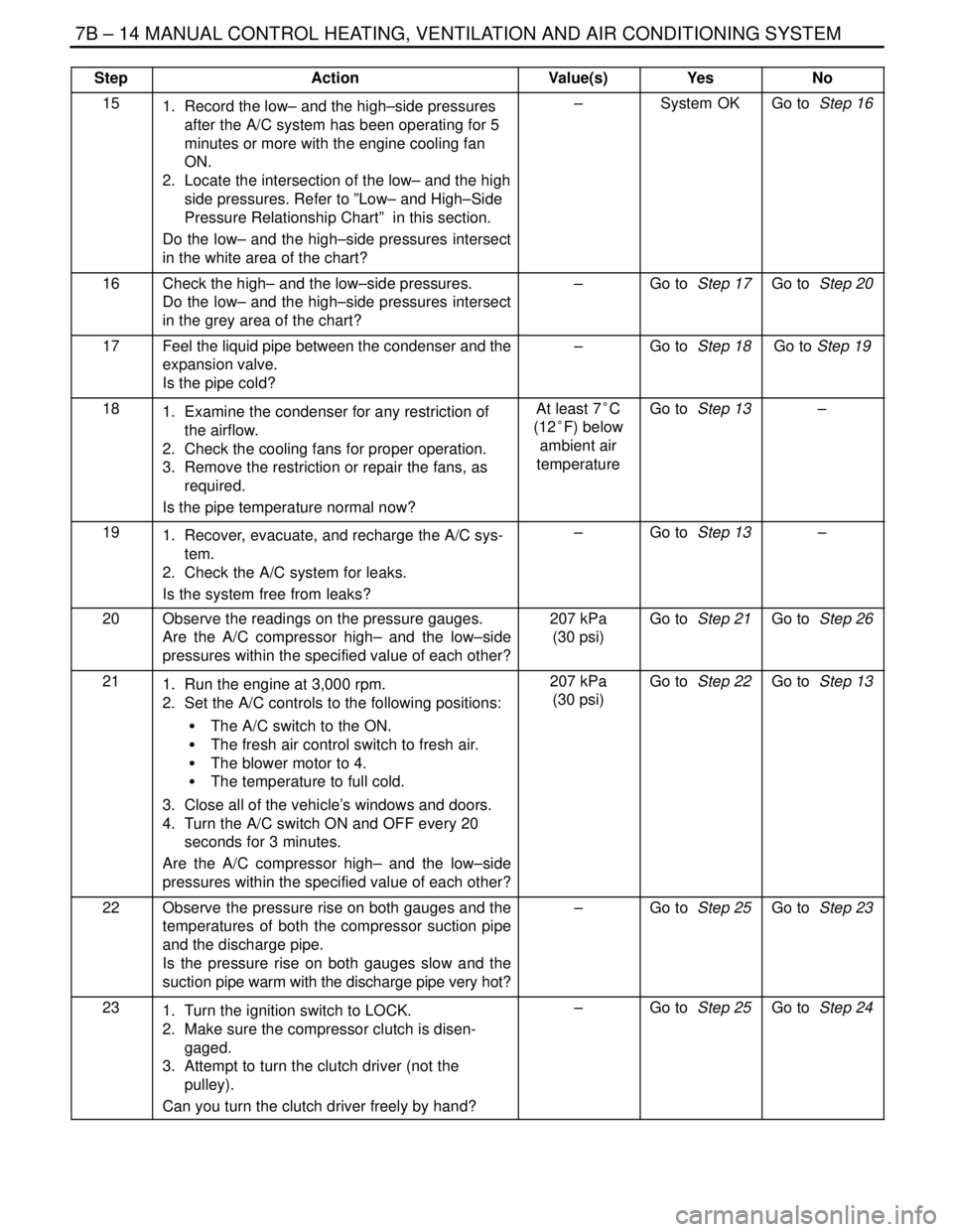
7B – 14IMANUAL CONTROL HEATING, VENTILATION AND AIR CONDITIONING SYSTEM
DAEWOO V–121 BL4
StepNo Yes Value(s) Action
151. Record the low– and the high–side pressures
after the A/C system has been operating for 5
minutes or more with the engine cooling fan
ON.
2. Locate the intersection of the low– and the high
side pressures. Refer to ”Low– and High–Side
Pressure Relationship Chart” in this section.
Do the low– and the high–side pressures intersect
in the white area of the chart?–System OKGo to Step 16
16Check the high– and the low–side pressures.
Do the low– and the high–side pressures intersect
in the grey area of the chart?–Go to Step 17Go to Step 20
17Feel the liquid pipe between the condenser and the
expansion valve.
Is the pipe cold?–Go to Step 18Go to Step 19
181. Examine the condenser for any restriction of
the airflow.
2. Check the cooling fans for proper operation.
3. Remove the restriction or repair the fans, as
required.
Is the pipe temperature normal now?At least 7°C
(12°F) below
ambient air
temperatureGo to Step 13–
191. Recover, evacuate, and recharge the A/C sys-
tem.
2. Check the A/C system for leaks.
Is the system free from leaks?–Go to Step 13–
20Observe the readings on the pressure gauges.
Are the A/C compressor high– and the low–side
pressures within the specified value of each other?207 kPa
(30 psi)Go to Step 21Go to Step 26
211. Run the engine at 3,000 rpm.
2. Set the A/C controls to the following positions:
S The A/C switch to the ON.
S The fresh air control switch to fresh air.
S The blower motor to 4.
S The temperature to full cold.
3. Close all of the vehicle’s windows and doors.
4. Turn the A/C switch ON and OFF every 20
seconds for 3 minutes.
Are the A/C compressor high– and the low–side
pressures within the specified value of each other?207 kPa
(30 psi)Go to Step 22Go to Step 13
22Observe the pressure rise on both gauges and the
temperatures of both the compressor suction pipe
and the discharge pipe.
Is the pressure rise on both gauges slow and the
suction pipe warm with the discharge pipe very hot?–Go to Step 25Go to Step 23
231. Turn the ignition switch to LOCK.
2. Make sure the compressor clutch is disen-
gaged.
3. Attempt to turn the clutch driver (not the
pulley).
Can you turn the clutch driver freely by hand?–Go to Step 25Go to Step 24
Page 2017 of 2643
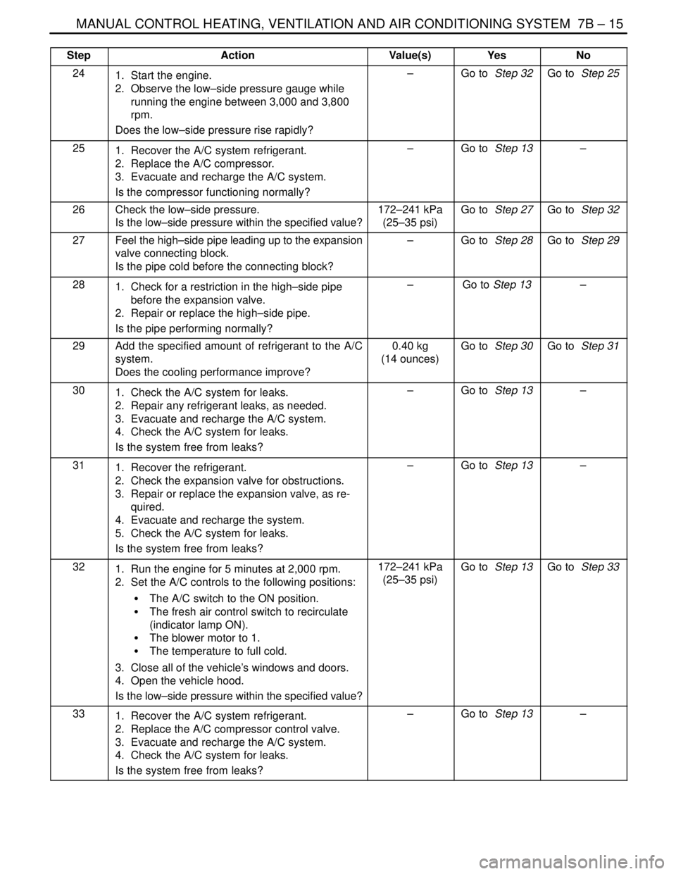
MANUAL CONTROL HEATING, VENTILATION AND AIR CONDITIONING SYSTEM 7B – 15
DAEWOO V–121 BL4
StepNo Yes Value(s) Action
241. Start the engine.
2. Observe the low–side pressure gauge while
running the engine between 3,000 and 3,800
rpm.
Does the low–side pressure rise rapidly?–Go to Step 32Go to Step 25
251. Recover the A/C system refrigerant.
2. Replace the A/C compressor.
3. Evacuate and recharge the A/C system.
Is the compressor functioning normally?–Go to Step 13–
26Check the low–side pressure.
Is the low–side pressure within the specified value?172–241 kPa
(25–35 psi)Go to Step 27Go to Step 32
27Feel the high–side pipe leading up to the expansion
valve connecting block.
Is the pipe cold before the connecting block?–Go to Step 28Go to Step 29
281. Check for a restriction in the high–side pipe
before the expansion valve.
2. Repair or replace the high–side pipe.
Is the pipe performing normally?–Go to Step 13–
29Add the specified amount of refrigerant to the A/C
system.
Does the cooling performance improve?0.40 kg
(14 ounces)Go to Step 30Go to Step 31
301. Check the A/C system for leaks.
2. Repair any refrigerant leaks, as needed.
3. Evacuate and recharge the A/C system.
4. Check the A/C system for leaks.
Is the system free from leaks?–Go to Step 13–
311. Recover the refrigerant.
2. Check the expansion valve for obstructions.
3. Repair or replace the expansion valve, as re-
quired.
4. Evacuate and recharge the system.
5. Check the A/C system for leaks.
Is the system free from leaks?–Go to Step 13–
321. Run the engine for 5 minutes at 2,000 rpm.
2. Set the A/C controls to the following positions:
S The A/C switch to the ON position.
S The fresh air control switch to recirculate
(indicator lamp ON).
S The blower motor to 1.
S The temperature to full cold.
3. Close all of the vehicle’s windows and doors.
4. Open the vehicle hood.
Is the low–side pressure within the specified value?172–241 kPa
(25–35 psi)Go to Step 13Go to Step 33
331. Recover the A/C system refrigerant.
2. Replace the A/C compressor control valve.
3. Evacuate and recharge the A/C system.
4. Check the A/C system for leaks.
Is the system free from leaks?–Go to Step 13–
Page 2095 of 2643
7D – 40IAUTOMATIC TEMPERATURE CONTROL HEATING, VENTILATION, AND AIR CONDITIONING SYSTEM
DAEWOO V–121 BL4
GENERAL DESCRIPTION
AND SYSTEM OPERATION
GENERAL INFORMATION
THE V5 SYSTEM
Refer to Section 7B, Manual Control Heating, Ventilation,
and Air Conditioning System,for general information de-
tails for the following:
S System Components – Functional.
S The V5 A/C System.
S V5 Compressor – Description of Operation.
S V5 Compressor – General Description.
SYSTEM COMPONENTS–CONTROL
Controller
The operation of the A/C system is controlled by the
switches on the control head. This console–mounted
heating and ventilation system contains the following
knobs and display:
Temperature Control Push Knobs
1. Raise the temperature of the air entering the ve-
hicle by pressing the top switch, with the red arrow
pointing upward.
2. Lower the temperature by pressing the bottom
switch, with the blue arrow pointing downward.
3. Actuate the air mix door by an electric motor.
4. Vary the mix of the air passing through the heater
core with the air bypassing the core.
Each press of a switch changes the set temperature by in-
crements of 0.5°C (1°F). This is shown in the temperature
window on the function display.
The Function Display
This is an LCD display indicating the status of the control
settings selected. Starting from the left end of the display,
the sections are as follows:
1. Temperature setting – Indicates the temperature set
with the temperature control knob.
2. Auto status – Indicates whether the system is oper-
ating in the full auto mode or the manual mode.
3. Defroster icon – Indicates manual selection of full
defrost mode.
4. Mode – Indicated by icon, the mode chosen by the
system in auto (or by the operator in manual) is
shown by an illumination arrow indicating the air
path.
5. A/C – A snowflake icon indicating whether the A/C
is ON or OFF.
6. Fan speed – Indicates the fan speed by illuminating
a bar based on the segment at the front, for low
speed, and adding additional segments in order up
to the fifth, for high speed.Eight Additional Push Knobs
1. Full defrost – Causes the mode motors to direct all
air to the windshield and aide window outlets for
maximum defrosting.
2. Air intake – Switches between fresh air intake, the
default, and recirculating air. Airflow arrows on the
display indicate the mode in effect.
3. Full Auto Switch – Maintains the set temperature
automatically. In this mode, the fully automatic tem-
perature control (FATC) system controls the follow-
ing:
S The air mix door motor.
S The mode door motor.
S The blower motor speed.
S The inlet air door motor.
S A/C ON/OFF.
4. OFF Switch – Turns the automatic air conditioning
and fan control off.
5. Mode Switch – Allows manual selection of the air-
flow direction.
S Selection is shown on the function display.
S Each time the mode switch is pressed, the next
function is displayed.
6. A/C Switch – Allows manual selection and control
of the air conditioning function.
7. Fan Control Switch – Allows manual selection
among five fan speeds.
8. Defogger Switch – Turns on the electric defogging
heater in the rear window and the outside rearview
mirrors, if the vehicle is equipped with heated mir-
rors.
Pressure Transducer
Pressure transducer switching incorporates the functions
of the high–pressure and the low–pressure cutout
switches along with the fan cycling switch. The pressure
transducer is located in the high–side liquid refrigerant line
behind the right strut tower, between the right strut tower
and the fire wall. The output from this pressure transducer
goes to the electronic control module (ECM), which con-
trols the compressor function based on the pressure sig-
nal.
Wide–Open Throttle (WOT) Compressor
Cutoff
During full–throttle acceleration, the throttle position sen-
sor (TPS) sends a signal to the ECM, which then controls
the compressor clutch.
High RPM Cutoff
As engine rpm approaches the maximum limit, the ECM
will disengage the compressor clutch until the engine
slows to a lower rpm.
Page 2199 of 2643
SUPPLEMENTAL INFLATABLE RESTRAINTS (SIR) 8B – 95
DAEWOO V–121 BL4
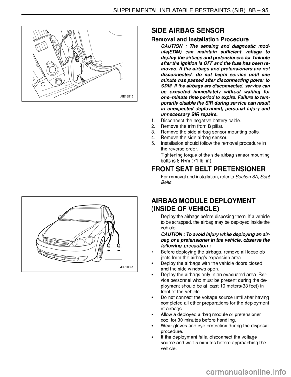
SIDE AIRBAG SENSOR
Removal and Installation Procedure
CAUTION : The sensing and diagnostic mod-
ule(SDM) can maintain sufficient voltage to
deploy the airbags and pretensioners for 1minute
after the ignition is OFF and the fuse has been re-
moved. If the airbags and pretensioners are not
disconnected, do not begin service until one
minute has passed after disconnecting power to
SDM. If the airbags are disconnected, service can
be executed immediately without waiting for
one–minute time period to expire. Failure to tem-
porarily disable the SIR during service can result
in unexpected deployment, personal injury and
unnecessary SIR repairs.
1. Disconnect the negative battery cable.
2. Remove the trim from B pillar.
3. Remove the side airbag sensor mounting bolts.
4. Remove the side airbag sensor.
5. Installation should follow the removal procedure in
the reverse order.
Tightening torque of the side airbag sensor mounting
bolts is 8 NSm (71 lb–in).
FRONT SEAT BELT PRETENSIONER
For removal and installation, refer to Section 8A, Seat
Belts.
AIRBAG MODULE DEPLOYMENT
(INSIDE OF VEHICLE)
Deploy the airbags before disposing them. If a vehicle
to be scrapped, the airbag may be deployed inside the
vehicle.
CAUTION : To avoid injury while deploying an air-
bag or a pretensioner in the vehicle, observe the
following precaution :
S Before deploying the airbags, remove all loose ob-
jects from the airbag’s expansion area.
S Deploy the airbags with the vehicle doors closed
and the side windows open.
S Deploy the airbags only in an evacuated area. Ser-
vice personnel who must be present during the de-
ployment should be at least 10 meters(33 feet) in
front of the vehicle.
S Do not connect the voltage source until after having
completed all other preparations for the deployment
of airbags.
S Allow a deployed airbag module or pretensioner
cool for 30 minutes before handling.
S Wear gloves and eye protection during the disposal
procedure.
S If the deployment fails, disconnect the voltage
source and wait 5 minutes before approaching the
vehicle.
Page 2219 of 2643
BODY WIRING SYSTEM 9A – 13
DAEWOO V–121 BL4
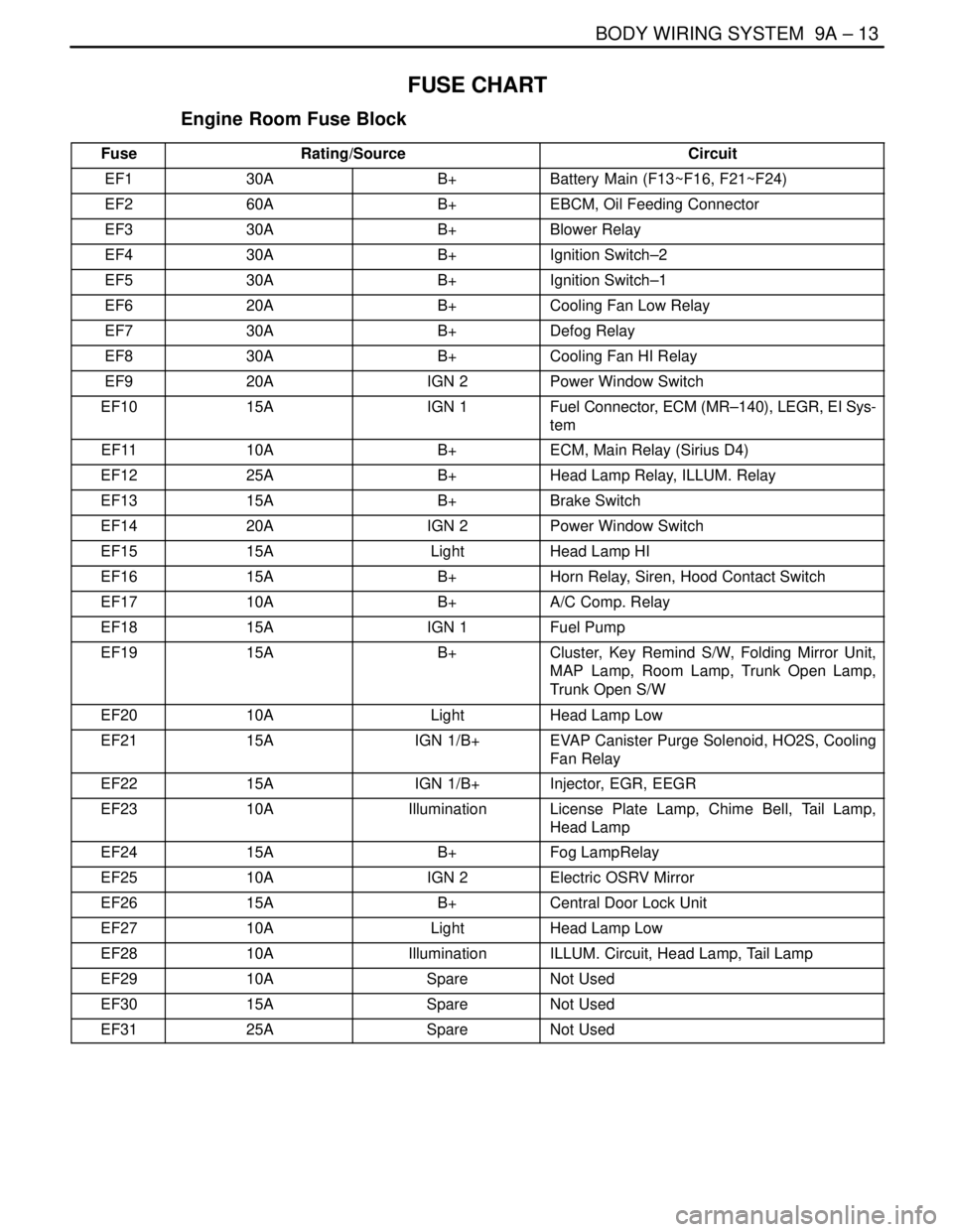
FUSE CHART
Engine Room Fuse Block
FuseRating/SourceCircuit
EF130AB+Battery Main (F13~F16, F21~F24)
EF260AB+EBCM, Oil Feeding Connector
EF330AB+Blower Relay
EF430AB+Ignition Switch–2
EF530AB+Ignition Switch–1
EF620AB+Cooling Fan Low Relay
EF730AB+Defog Relay
EF830AB+Cooling Fan HI Relay
EF920AIGN 2Power Window Switch
EF1015AIGN 1Fuel Connector, ECM (MR–140), LEGR, EI Sys-
tem
EF1110AB+ECM, Main Relay (Sirius D4)
EF1225AB+Head Lamp Relay, ILLUM. Relay
EF1315AB+Brake Switch
EF1420AIGN 2Power Window Switch
EF1515ALightHead Lamp HI
EF1615AB+Horn Relay, Siren, Hood Contact Switch
EF1710AB+A/C Comp. Relay
EF1815AIGN 1Fuel Pump
EF1915AB+Cluster, Key Remind S/W, Folding Mirror Unit,
MAP Lamp, Room Lamp, Trunk Open Lamp,
Trunk Open S/W
EF2010ALightHead Lamp Low
EF2115AIGN 1/B+EVAP Canister Purge Solenoid, HO2S, Cooling
Fan Relay
EF2215AIGN 1/B+Injector, EGR, EEGR
EF2310AIlluminationLicense Plate Lamp, Chime Bell, Tail Lamp,
Head Lamp
EF2415AB+Fog LampRelay
EF2510AIGN 2Electric OSRV Mirror
EF2615AB+Central Door Lock Unit
EF2710ALightHead Lamp Low
EF2810AIlluminationILLUM. Circuit, Head Lamp, Tail Lamp
EF2910ASpareNot Used
EF3015ASpareNot Used
EF3125ASpareNot Used
Page 2220 of 2643
9A – 14IBODY WIRING SYSTEM
DAEWOO V–121 BL4
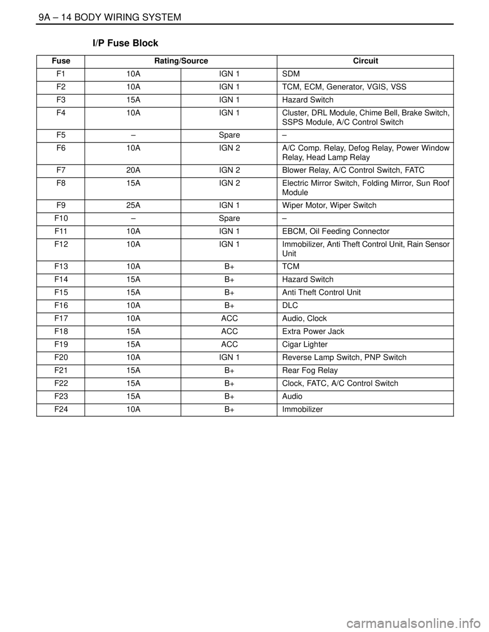
I/P Fuse Block
FuseRating/SourceCircuit
F110AIGN 1SDM
F210AIGN 1TCM, ECM, Generator, VGIS, VSS
F315AIGN 1Hazard Switch
F410AIGN 1Cluster, DRL Module, Chime Bell, Brake Switch,
SSPS Module, A/C Control Switch
F5–Spare–
F610AIGN 2A/C Comp. Relay, Defog Relay, Power Window
Relay, Head Lamp Relay
F720AIGN 2Blower Relay, A/C Control Switch, FATC
F815AIGN 2Electric Mirror Switch, Folding Mirror, Sun Roof
Module
F925AIGN 1Wiper Motor, Wiper Switch
F10–Spare–
F1110AIGN 1EBCM, Oil Feeding Connector
F1210AIGN 1Immobilizer, Anti Theft Control Unit, Rain Sensor
Unit
F1310AB+TCM
F1415AB+Hazard Switch
F1515AB+Anti Theft Control Unit
F1610AB+DLC
F1710AACCAudio, Clock
F1815AACCExtra Power Jack
F1915AACCCigar Lighter
F2010AIGN 1Reverse Lamp Switch, PNP Switch
F2115AB+Rear Fog Relay
F2215AB+Clock, FATC, A/C Control Switch
F2315AB+Audio
F2410AB+Immobilizer
Page 2272 of 2643
9B – 46ILITHING SYSTEMS
DAEWOO V–121 BL4
GENERAL DESCRIPTION
AND SYSTEM OPERATION
HEADLAMPS–ON REMINDER CHIME
When the headlamp switch is in the headlamps–on or
parking lamps–on position, voltage is applied to the chime
module. When the ignition is in ON, ACC or START, volt-
age is applied through the fuse block to the module. These
two voltages are sensed, and the chime module is not
sounded.
When the ignition is not in ON, ACC or START, the module
loses voltage. The chime module senses change. If the
voltage is still available, it is applied to sound the chime.
The chime can be turned off by turning the headlamp
switch off. The module no longer senses voltage from the
headlamp switch, so the chime module does not sound.
HEADLAMPS
The headlamps are controlled by the multifunction lever
located on the left side of the steering column. They will
come on with the ignition switch in any position. Turning
the headlamp switch to the first position turns on the park-
ing lamps, the license plate lamps and the instrument pan-
el illumination. Turning the switch to the second position
turns on all of the previous lamps and the headlamps.
Turning the switch to the OFF position turns off all the
lamps.
Headlamp high beams and low beams are also controlled
by this lever. When the headlamps are on, pushing the le-
ver away from the driver until the switch clicks changes the
lamp from low beam to high beam. An indicator lamp on
the instrument cluster assembly will come on when the
high beam headlamps are on. To return the headlamps to
low beam, pull the lever toward the driver.
The headlamps must be aimed for proper illumination of
the road. Headlamp aim should be checked whenever a
new headlamp assembly is installed, or whenever service
repairs to the front end area may have disturbed the head-
lamp assembly or its mountings.
DAYTIME RUNNING LAMPS
The Daytime Running Lamps (DRL) will come on when:
S The ignition is ON.
S The light is OFF.
S The parking brake is released.
When the exterior lights are on, the DRL will turn off. To
turn the DRL off when idling, apply the parking brake.
PARKING AND TURN SIGNAL LAMPS
The parking lamps can be turned on by turning the lighting
switch to the first position. The parking lamps can be
turned off by turning the switch to the OFF position.When the turn signals are activated, the front and rear turn
signal lamps flash to signal a turn. The turn signals work
only when the ignition is ON.
The turn signals are controlled by the light switch on the
left side of the steering column. Moving the lever all the
way up or down (past the detent) will turn on the front and
rear turn signals. When the turn is completed, the lever will
return to horizontal and the turn signals will stop flashing.
For changing lanes, or for shallow turns in which the steer-
ing wheel does not turn far enough to cancel the signal,
move the signal lever only to the first detent and hold it
there. When the lever is released, it will return to horizontal
and the turn signals will cancel.
FOG LAMPS
The fog lamp switch is on the instrument panel to the right
of the steering column. To use the fog lamps, first turn on
the headlamps or the parking lamps. Then push the fog
lamp switch. The indicator light in the switch will illuminate
to indicate that the fog lamps are on. Push the switch again
to turn off the fog lamps. The indicator light will then go off.
The fog lamps should not be used as a substitute for the
headlamps.
The fog lamps must be aimed for proper illumination of the
road. Fog lamp aim should be checked when a new bulb
is installed or if service or repairs in the front end area may
have disturbed the fog lamp mountings.
REAR COMBINATION LAMPS
The taillamps, stoplamps, turn signal lamps and backup
lamp are one assembly.
Turning on either the headlamps or the parking lamps will
also turn on the taillamps. When the brake pedal is
pushed, the taillamps will glow brighter to serve as sto-
plamps.
The center high–mounted stoplamp is located in the rear
window and will come on when the brake pedal is pressed.
LICENSE PLATE LAMP
The license plate lamps will come on when the headlamps
or the parking lamps are on. The license plate lamps are
mounted above the license plate.
INTERIOR COURTESY LAMP
The courtesy lamp is located on the headliner just behind
the front seats. The lamp switch has three positions. If the
switch is left in the center position, the lamp will go on
whenever a door is opened and go off when it is closed.
In the ON position, the lamp will stay on until it is turned off.
In the OFF position, the lamp will not come on, even when
a door is opened.
LUGGAGE COMPARTMENT LAMP
The luggage compartment lamp is located under the deck
lid sill plate on the notchback. The lamp is located on the
left–side wheelhouse trim panel on the hatchback. It will
come on whenever the luggage compartment is opened.