DAEWOO NUBIRA 2004 Service Repair Manual
Manufacturer: DAEWOO, Model Year: 2004, Model line: NUBIRA, Model: DAEWOO NUBIRA 2004Pages: 2643, PDF Size: 80.54 MB
Page 2411 of 2643

9N – 8IFRAME AND UNDERBODY
DAEWOO V–121 BL4
GENERAL DESCRIPTION
AND SYSTEM OPERATION
GENERAL BODY CONSTRUCTION
This vehicle is constructed with a unitized body which in-
corporates integral front and rear frame side rails.
The front suspension lower control arms are bolted to and
retained by supports, one each on the right and left sides.
The front suspension lower control arm supports are at-
tached to the underbody with three bolts at two locations.
The engine is bolted to the integral front side rails. The
suspension strut towers must be dimensionally correct in
relation to the remainder of the underbody in order to main-
tain specified suspension strut and caster/ camber angles.Since the individual underbody parts contribute directly to
the overall strength of the body, it is essential to observe
proper welding techniques during service repair opera-
tions. The underbody parts should be properly sealed and
rustproofed whenever body repair operations destroy or
damage the original sealing and rustproofing. When rust-
proofing critical underbody parts, use a good–quality type
of air–dry primer, such as a corrosion–resistant chromate
or an equivalent material. Combination–type primer/sur-
facers are not recommended.
ENGINE UNDER COVERS
The engine under covers are molded pieces of plastic that
serve as shields for the underside of the engine. The cov-
ers help protect the engine from small rocks, gravel and
other objects that would otherwise come into contact with
the engine during normal driving conditions.
Page 2412 of 2643

SECTION : 9O
BUMPERS AND FASCIAS
CAUTION : Disconnect the negative battery cable before removing or installing any electrical unit or when a tool
or equipment could easily come in contact with exposed electrical terminals. Disconnecting this cable will help
prevent personal injury and damage to the vehicle. The ignition must also be in LOCK unless otherwise noted.
TABLE OF CONTENTS
SPECIFICATIONS9O–1 . . . . . . . . . . . . . . . . . . . . . . . . . .
Fastener Tightening Specifications 9O–1. . . . . . . . . . .
MAINTENANCE AND REPAIR9O–2 . . . . . . . . . . . . . . .
ON–VEHICLE SERVICE 9O–2. . . . . . . . . . . . . . . . . . . . .
Front Bumper Fascia 9O–2. . . . . . . . . . . . . . . . . . . . . . .
Front Bumper Energy Absorber 9O–3. . . . . . . . . . . . . . Front Bumper Impact Bar 9O–4. . . . . . . . . . . . . . . . . . .
Notchback Rear Bumper Fascia 9O–4. . . . . . . . . . . . .
Hatchback Rear Bumper Fascia 9O–6. . . . . . . . . . . . .
Rear Bumper Impact Bar 9O–7. . . . . . . . . . . . . . . . . . .
GENERAL DESCRIPTION AND SYSTEM
OPERATION9O–9 . . . . . . . . . . . . . . . . . . . . . . . . . . . . . .
Bumpers 9O–9. . . . . . . . . . . . . . . . . . . . . . . . . . . . . . . . .
SPECIFICATIONS
FASTENER TIGHTENING SPECIFICATIONS
ApplicationNSmLb–FtLb–In
Fender–to–Fascia Bolts10–89
Fender–to–Fascia Screws2–18
Front Impact Bar Bolts3929–
Lower Fascia Screws2–18
Luggage Compartment Fascia Bolts10–89
Luggage Compartment Fascia Screws2–18
Rear Wheel Well Fascia Bolts2–18
Page 2413 of 2643
9O – 2IBUMPERS AND FASCIAS
DAEWOO V–121 BL4
MAINTENANCE AND REPAIR
ON–VEHICLE SERVICE
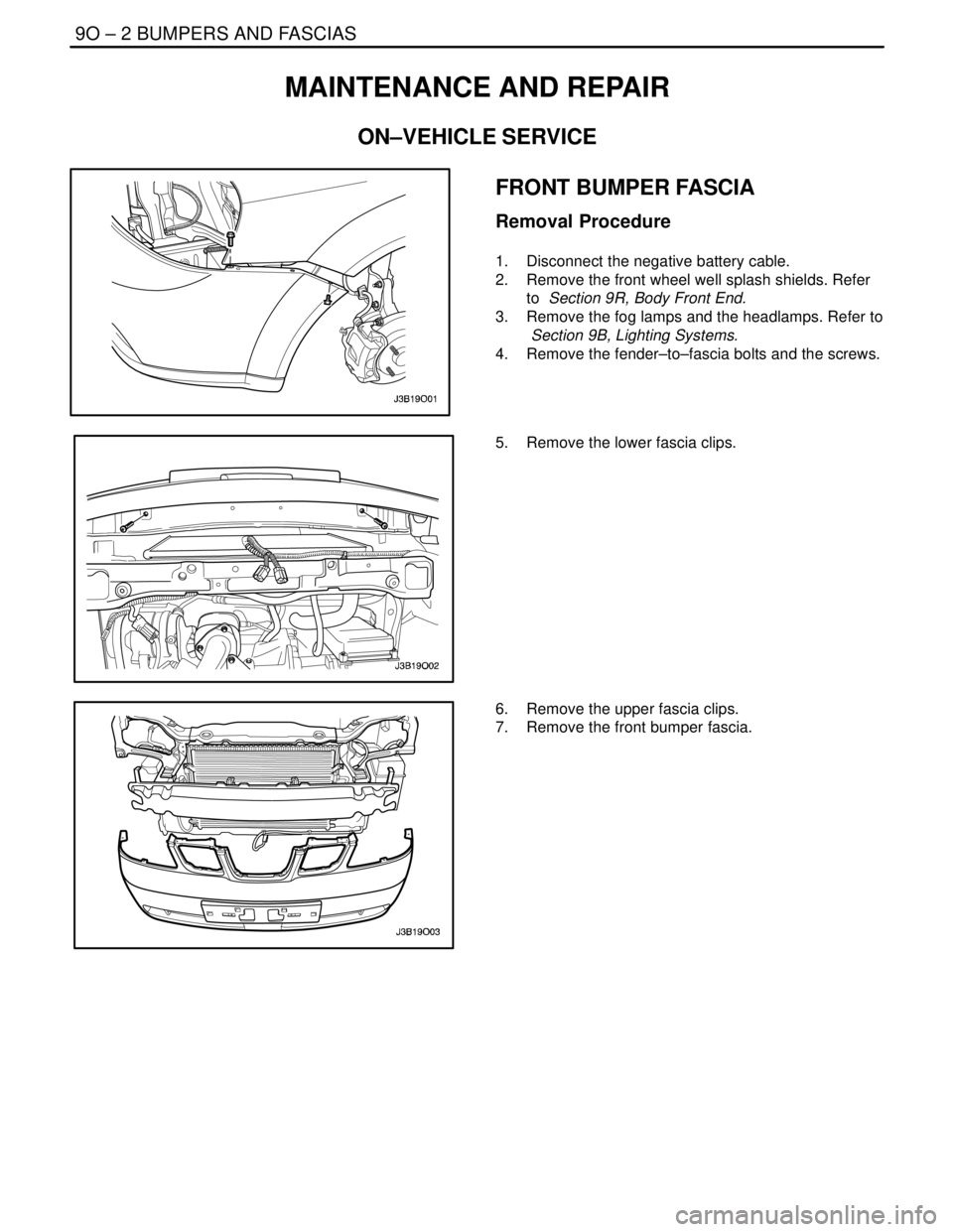
FRONT BUMPER FASCIA
Removal Procedure
1. Disconnect the negative battery cable.
2. Remove the front wheel well splash shields. Refer
to Section 9R, Body Front End.
3. Remove the fog lamps and the headlamps. Refer to
Section 9B, Lighting Systems.
4. Remove the fender–to–fascia bolts and the screws.
5. Remove the lower fascia clips.
6. Remove the upper fascia clips.
7. Remove the front bumper fascia.
Page 2414 of 2643
BUMPERS AND FASCIAS 9O – 3
DAEWOO V–121 BL4
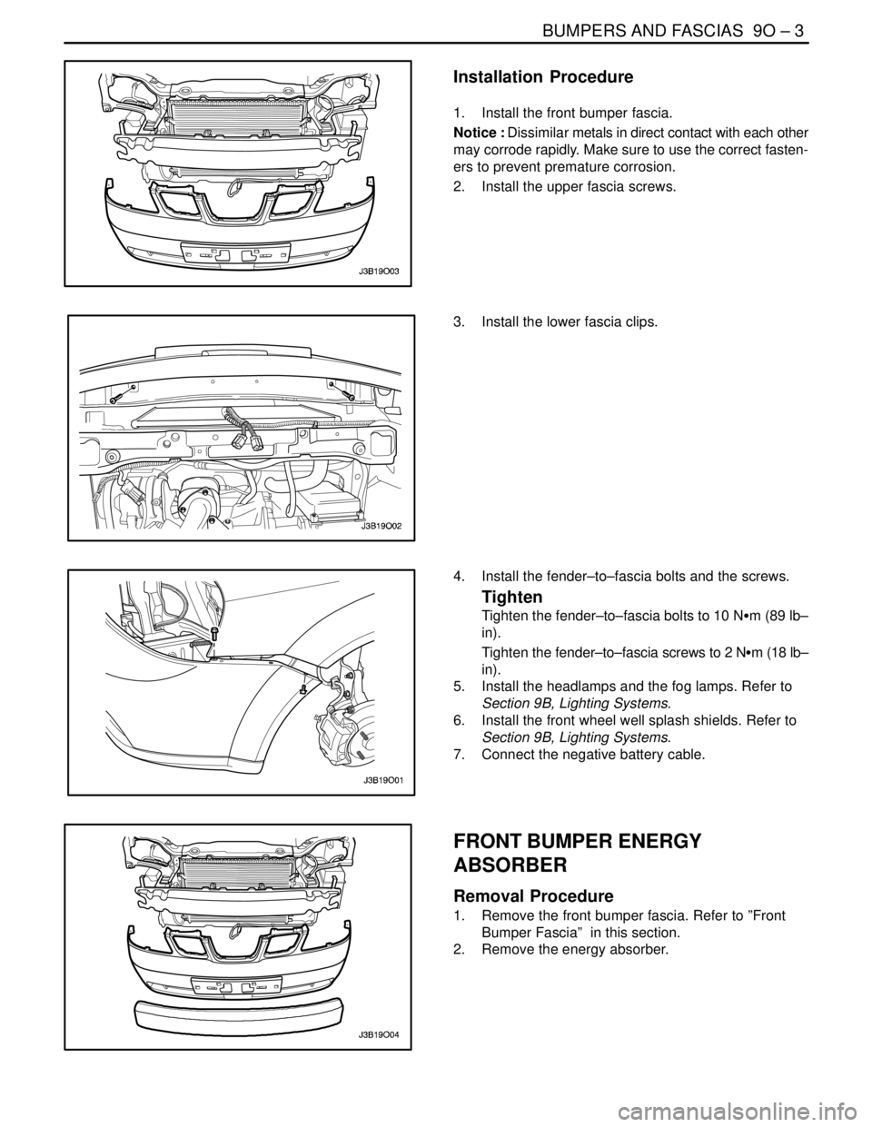
Installation Procedure
1. Install the front bumper fascia.
Notice : Dissimilar metals in direct contact with each other
may corrode rapidly. Make sure to use the correct fasten-
ers to prevent premature corrosion.
2. Install the upper fascia screws.
3. Install the lower fascia clips.
4. Install the fender–to–fascia bolts and the screws.
Tighten
Tighten the fender–to–fascia bolts to 10 NSm (89 lb–
in).
Tighten the fender–to–fascia screws to 2 NSm (18 lb–
in).
5. Install the headlamps and the fog lamps. Refer to
Section 9B, Lighting Systems.
6. Install the front wheel well splash shields. Refer to
Section 9B, Lighting Systems.
7. Connect the negative battery cable.
FRONT BUMPER ENERGY
ABSORBER
Removal Procedure
1. Remove the front bumper fascia. Refer to ”Front
Bumper Fascia” in this section.
2. Remove the energy absorber.
Page 2415 of 2643
9O – 4IBUMPERS AND FASCIAS
DAEWOO V–121 BL4
Installation Procedure
1. Install the energy absorber.
2. Install the front bumper fascia. Refer to ”Front
Bumper Fascia” in this section.
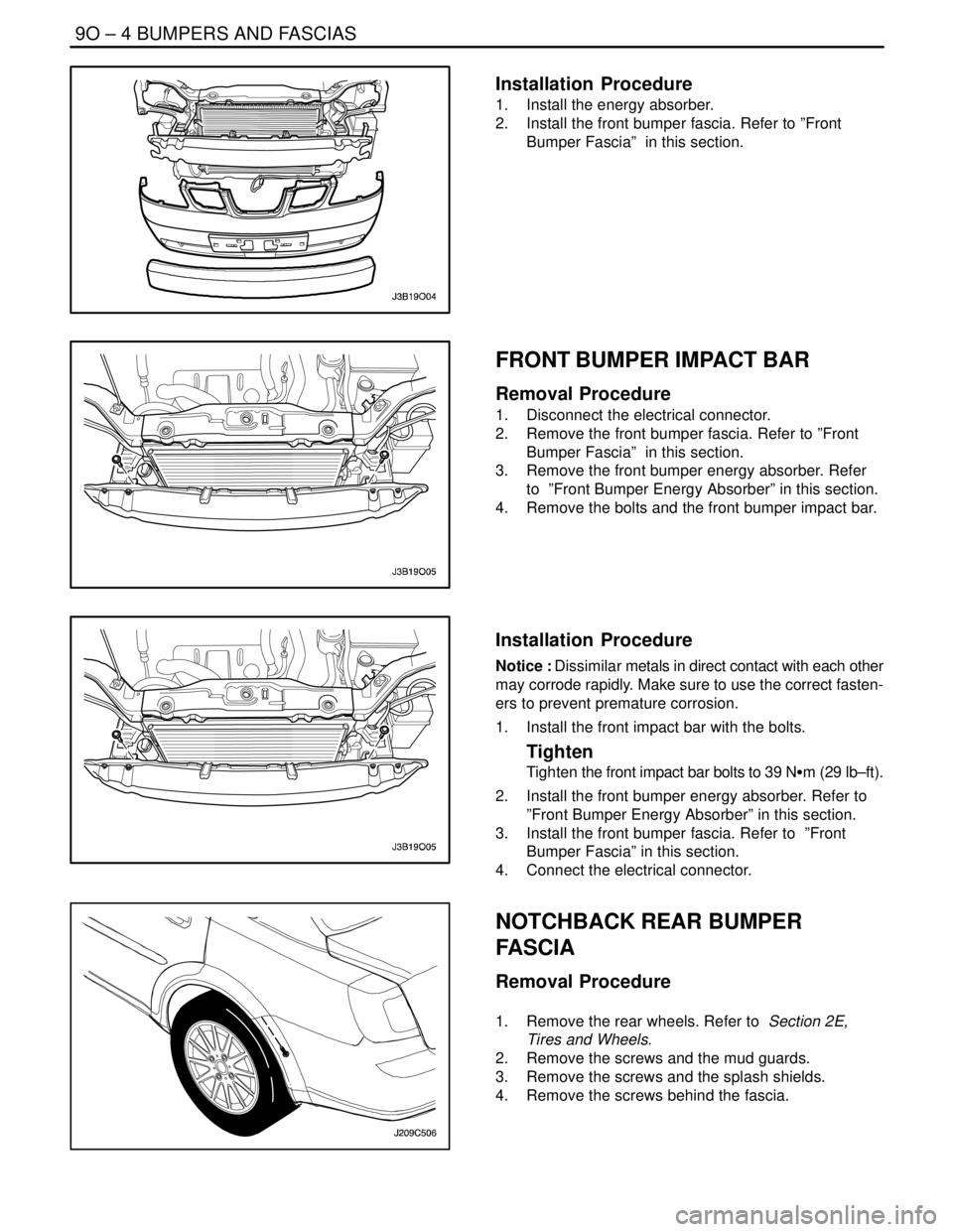
FRONT BUMPER IMPACT BAR
Removal Procedure
1. Disconnect the electrical connector.
2. Remove the front bumper fascia. Refer to ”Front
Bumper Fascia” in this section.
3. Remove the front bumper energy absorber. Refer
to ”Front Bumper Energy Absorber” in this section.
4. Remove the bolts and the front bumper impact bar.
Installation Procedure
Notice : Dissimilar metals in direct contact with each other
may corrode rapidly. Make sure to use the correct fasten-
ers to prevent premature corrosion.
1. Install the front impact bar with the bolts.
Tighten
Tighten the front impact bar bolts to 39 NSm (29 lb–ft).
2. Install the front bumper energy absorber. Refer to
”Front Bumper Energy Absorber” in this section.
3. Install the front bumper fascia. Refer to ”Front
Bumper Fascia” in this section.
4. Connect the electrical connector.
NOTCHBACK REAR BUMPER
FASCIA
Removal Procedure
1. Remove the rear wheels. Refer to Section 2E,
Tires and Wheels.
2. Remove the screws and the mud guards.
3. Remove the screws and the splash shields.
4. Remove the screws behind the fascia.
Page 2416 of 2643
BUMPERS AND FASCIAS 9O – 5
DAEWOO V–121 BL4
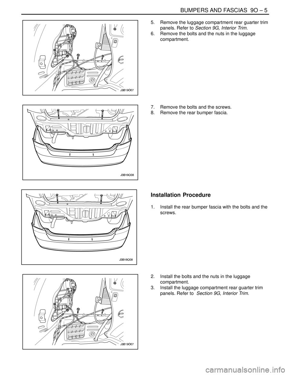
5. Remove the luggage compartment rear guarter trim
panels. Refer to Section 9G, Interior Trim.
6. Remove the bolts and the nuts in the luggage
compartment.
7. Remove the bolts and the screws.
8. Remove the rear bumper fascia.
Installation Procedure
1. Install the rear bumper fascia with the bolts and the
screws.
2. Install the bolts and the nuts in the luggage
compartment.
3. Install the luggage compartment rear guarter trim
panels. Refer to Section 9G, Interior Trim.
Page 2417 of 2643
9O – 6IBUMPERS AND FASCIAS
DAEWOO V–121 BL4
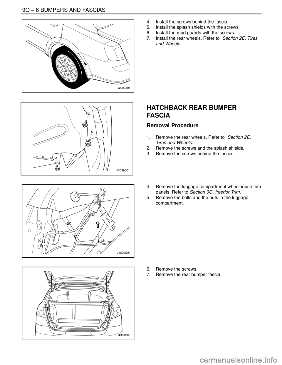
4. Install the screws behind the fascia.
5. Install the splash shields with the screws.
6. Install the mud guards with the screws.
7. Install the rear wheels. Refer to Section 2E, Tires
and Wheels.
HATCHBACK REAR BUMPER
FASCIA
Removal Procedure
1. Remove the rear wheels. Refer to Section 2E,
Tires and Wheels.
2. Remove the screws and the splash shields.
3. Remove the screws behind the fascia.
4. Remove the luggage compartment wheelhouse trim
panels. Refer to Section 9G, Interior Trim.
5. Remove the bolts and the nuts in the luggage
compartment.
6. Remove the screws.
7. Remove the rear bumper fascia.
Page 2418 of 2643
BUMPERS AND FASCIAS 9O – 7
DAEWOO V–121 BL4
Installation Procedure
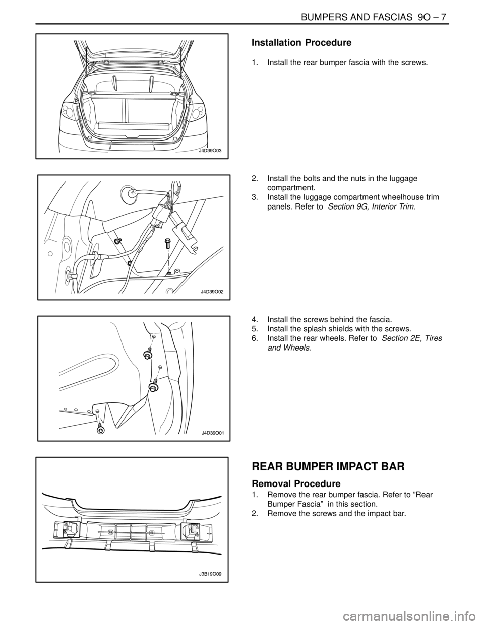
1. Install the rear bumper fascia with the screws.
2. Install the bolts and the nuts in the luggage
compartment.
3. Install the luggage compartment wheelhouse trim
panels. Refer to Section 9G, Interior Trim.
4. Install the screws behind the fascia.
5. Install the splash shields with the screws.
6. Install the rear wheels. Refer to Section 2E, Tires
and Wheels.
REAR BUMPER IMPACT BAR
Removal Procedure
1. Remove the rear bumper fascia. Refer to ”Rear
Bumper Fascia” in this section.
2. Remove the screws and the impact bar.
Page 2419 of 2643

9O – 8IBUMPERS AND FASCIAS
DAEWOO V–121 BL4
Installation Procedure
1. Install the impact bar with the screws.
2. Install the rear bumper fascia. Refer to ”Rear
Bumper Fascia” in this section.
Page 2420 of 2643

BUMPERS AND FASCIAS 9O – 9
DAEWOO V–121 BL4
GENERAL DESCRIPTION
AND SYSTEM OPERATION
BUMPERS
The bumper systems are designed to sustain a collision
into a fixed barrier at either 8 km/h (5 mph) or 4 km/h (2.5
mph) without damage. After absorbing the energy of a col-lision, the bumper systems restore themselves to their
original positions. The bumpers feature an internal foam
energy absorber and a polymer fascia cover.