seats DAEWOO NUBIRA 2004 Service Owner's Guide
[x] Cancel search | Manufacturer: DAEWOO, Model Year: 2004, Model line: NUBIRA, Model: DAEWOO NUBIRA 2004Pages: 2643, PDF Size: 80.54 MB
Page 2362 of 2643
9H – 6ISEATS
DAEWOO V–121 BL4
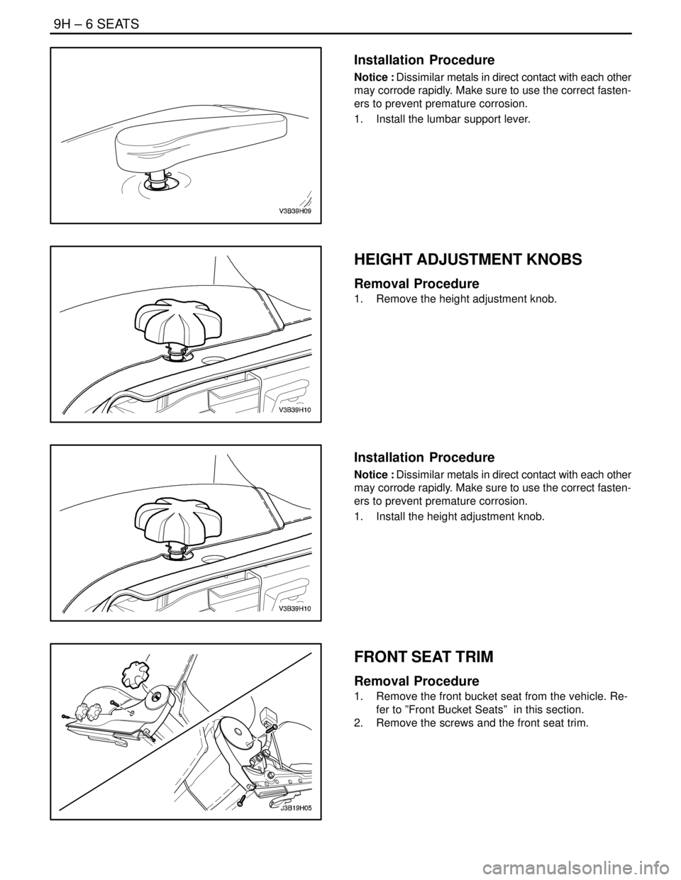
Installation Procedure
Notice : Dissimilar metals in direct contact with each other
may corrode rapidly. Make sure to use the correct fasten-
ers to prevent premature corrosion.
1. Install the lumbar support lever.
HEIGHT ADJUSTMENT KNOBS
Removal Procedure
1. Remove the height adjustment knob.
Installation Procedure
Notice : Dissimilar metals in direct contact with each other
may corrode rapidly. Make sure to use the correct fasten-
ers to prevent premature corrosion.
1. Install the height adjustment knob.
FRONT SEAT TRIM
Removal Procedure
1. Remove the front bucket seat from the vehicle. Re-
fer to ”Front Bucket Seats” in this section.
2. Remove the screws and the front seat trim.
Page 2363 of 2643
SEATS 9H – 7
DAEWOO V–121 BL4
Installation Procedure
Notice : Dissimilar metals in direct contact with each other
may corrode rapidly. Make sure to use the correct fasten-
ers to prevent premature corrosion.
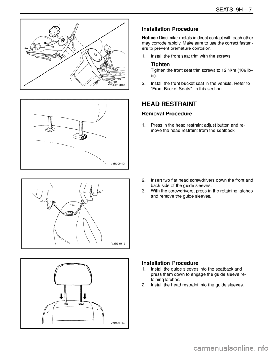
1. Install the front seat trim with the screws.
Tighten
Tighten the front seat trim screws to 12 NSm (106 lb–
in).
2. Install the front bucket seat in the vehicle. Refer to
”Front Bucket Seats” in this section.
HEAD RESTRAINT
Removal Procedure
1. Press in the head restraint adjust button and re-
move the head restraint from the seatback.
2. Insert two flat head screwdrivers down the front and
back side of the guide sleeves.
3. With the screwdrivers, press in the retaining latches
and remove the guide sleeves.
Installation Procedure
1. Install the guide sleeves into the seatback and
press them down to engage the guide sleeve re-
taining latches.
2. Install the head restraint into the guide sleeves.
Page 2364 of 2643
9H – 8ISEATS
DAEWOO V–121 BL4
REAR SEAT CUSHION
Removal Procedure
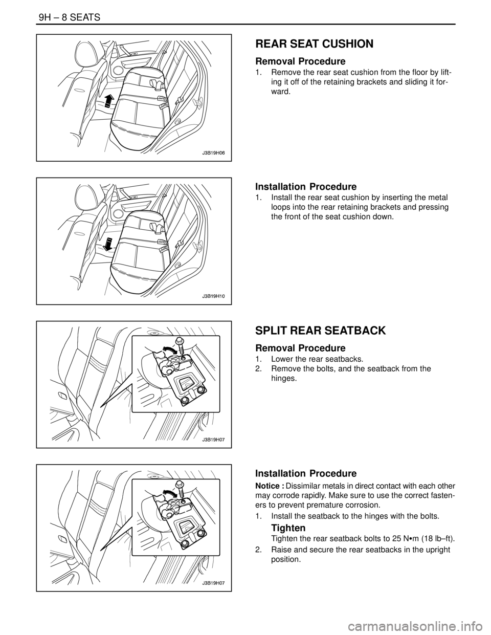
1. Remove the rear seat cushion from the floor by lift-
ing it off of the retaining brackets and sliding it for-
ward.
Installation Procedure
1. Install the rear seat cushion by inserting the metal
loops into the rear retaining brackets and pressing
the front of the seat cushion down.
SPLIT REAR SEATBACK
Removal Procedure
1. Lower the rear seatbacks.
2. Remove the bolts, and the seatback from the
hinges.
Installation Procedure
Notice : Dissimilar metals in direct contact with each other
may corrode rapidly. Make sure to use the correct fasten-
ers to prevent premature corrosion.
1. Install the seatback to the hinges with the bolts.
Tighten
Tighten the rear seatback bolts to 25 NSm (18 lb–ft).
2. Raise and secure the rear seatbacks in the upright
position.
Page 2365 of 2643
SEATS 9H – 9
DAEWOO V–121 BL4
SPLIT REAR SEATBACK HINGE
Removal Procedure
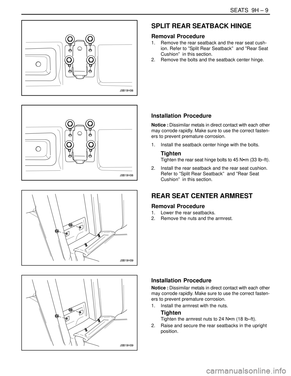
1. Remove the rear seatback and the rear seat cush-
ion. Refer to ”Split Rear Seatback” and ”Rear Seat
Cushion” in this section.
2. Remove the bolts and the seatback center hinge.
Installation Procedure
Notice : Dissimilar metals in direct contact with each other
may corrode rapidly. Make sure to use the correct fasten-
ers to prevent premature corrosion.
1. Install the seatback center hinge with the bolts.
Tighten
Tighten the rear seat hinge bolts to 45 NSm (33 lb–ft).
2. Install the rear seatback and the rear seat cushion.
Refer to ”Split Rear Seatback” and ”Rear Seat
Cushion” in this section.
REAR SEAT CENTER ARMREST
Removal Procedure
1. Lower the rear seatbacks.
2. Remove the nuts and the armrest.
Installation Procedure
Notice : Dissimilar metals in direct contact with each other
may corrode rapidly. Make sure to use the correct fasten-
ers to prevent premature corrosion.
1. Install the armrest with the nuts.
Tighten
Tighten the armrest nuts to 24 NSm (18 lb–ft).
2. Raise and secure the rear seatbacks in the upright
position.
Page 2366 of 2643
9H – 10ISEATS
DAEWOO V–121 BL4
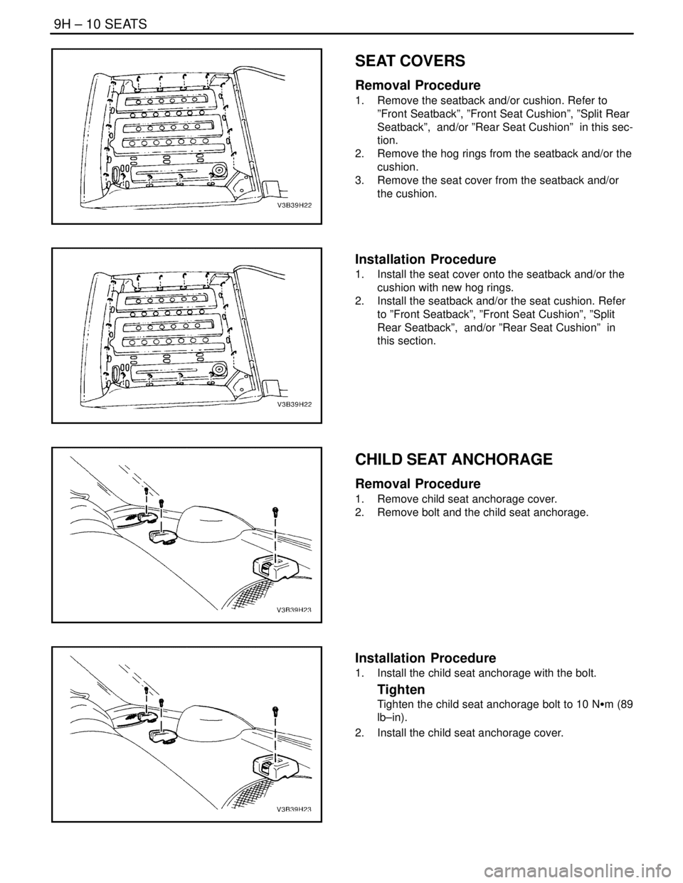
SEAT COVERS
Removal Procedure
1. Remove the seatback and/or cushion. Refer to
”Front Seatback”, ”Front Seat Cushion”, ”Split Rear
Seatback”, and/or ”Rear Seat Cushion” in this sec-
tion.
2. Remove the hog rings from the seatback and/or the
cushion.
3. Remove the seat cover from the seatback and/or
the cushion.
Installation Procedure
1. Install the seat cover onto the seatback and/or the
cushion with new hog rings.
2. Install the seatback and/or the seat cushion. Refer
to ”Front Seatback”, ”Front Seat Cushion”, ”Split
Rear Seatback”, and/or ”Rear Seat Cushion” in
this section.
CHILD SEAT ANCHORAGE
Removal Procedure
1. Remove child seat anchorage cover.
2. Remove bolt and the child seat anchorage.
Installation Procedure
1. Install the child seat anchorage with the bolt.
Tighten
Tighten the child seat anchorage bolt to 10 NSm (89
lb–in).
2. Install the child seat anchorage cover.
Page 2367 of 2643
SEATS 9H – 11
DAEWOO V–121 BL4
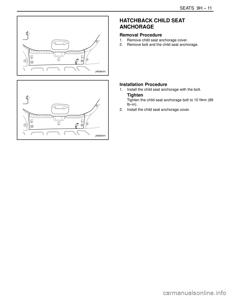
HATCHBACK CHILD SEAT
ANCHORAGE
Removal Procedure
1. Remove child seat anchorage cover.
2. Remove bolt and the child seat anchorage.
Installation Procedure
1. Install the child seat anchorage with the bolt.
Tighten
Tighten the child seat anchorage bolt to 10 NSm (89
lb–in).
2. Install the child seat anchorage cover.
Page 2368 of 2643

9H – 12ISEATS
DAEWOO V–121 BL4
GENERAL DESCRIPTION
AND SYSTEM OPERATION
SEATS
Do not attempt to change the designed seat position by al-
tering the designed seat adjuster–to–floor pan anchor pro-
visions or the seat adjuster–to–seat frame anchor provi-
sions. Changing the seat position could affect the
performance of the seat system.This vehicle is equipped with front bucket seats with sepa-
rate, adjustable head restraints, and a three–passenger
rear bench seat with an optional split folding rear seat. The
front bucket seats also have a recline, a height, and a lum-
bar adjustment. A power driver seat is optional. Seat cush-
ions and seatbacks have formed foam pads, which fit the
contours of the full panel seatback frame assembly and
the designed contour of the seat cushion frame.
Page 2458 of 2643
ROOF 9Q – 9
DAEWOO V–121 BL4
6. Remove the power sunroof control switch, if
equipped. Refer to ”Power Sunroof Control Switch”
in this section.
7. Remove the A–, B–, and C–pillar trim panels. Refer
to Section 9G, Interior Trim.
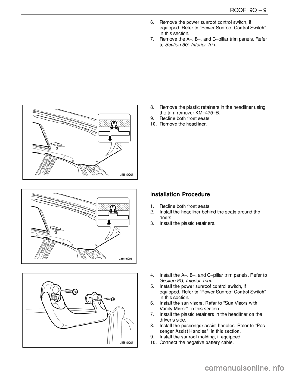
8. Remove the plastic retainers in the headliner using
the trim remover KM–475–B.
9. Recline both front seats.
10. Remove the headliner.
Installation Procedure
1. Recline both front seats.
2. Install the headliner behind the seats around the
doors.
3. Install the plastic retainers.
4. Install the A–, B–, and C–pillar trim panels. Refer to
Section 9G, Interior Trim.
5. Install the power sunroof control switch, if
equipped. Refer to ”Power Sunroof Control Switch”
in this section.
6. Install the sun visors. Refer to ”Sun Visors with
Vanity Mirror” in this section.
7. Install the plastic retainers in the headliner on the
driver’s side.
8. Install the passenger assist handles. Refer to ”Pas-
senger Assist Handles” in this section.
9. Install the sunroof molding, if equipped.
10. Connect the negative battery cable.
Page 2474 of 2643
BODY REAR END 9S – 3
DAEWOO V–121 BL4
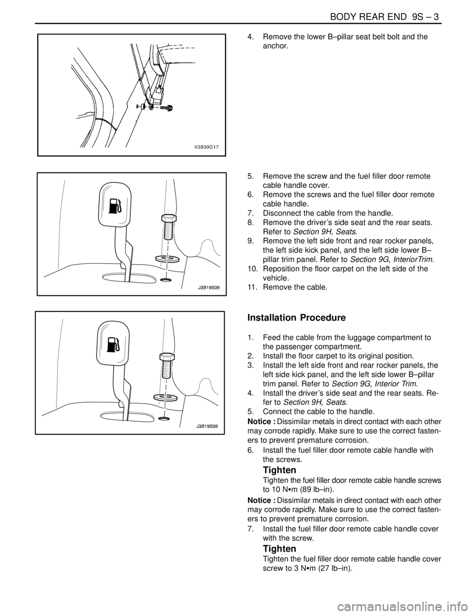
4. Remove the lower B–pillar seat belt bolt and the
anchor.
5. Remove the screw and the fuel filler door remote
cable handle cover.
6. Remove the screws and the fuel filler door remote
cable handle.
7. Disconnect the cable from the handle.
8. Remove the driver’s side seat and the rear seats.
Refer to Section 9H, Seats.
9. Remove the left side front and rear rocker panels,
the left side kick panel, and the left side lower B–
pillar trim panel. Refer to Section 9G, InteriorTrim.
10. Reposition the floor carpet on the left side of the
vehicle.
11. Remove the cable.
Installation Procedure
1. Feed the cable from the luggage compartment to
the passenger compartment.
2. Install the floor carpet to its original position.
3. Install the left side front and rear rocker panels, the
left side kick panel, and the left side lower B–pillar
trim panel. Refer to Section 9G, Interior Trim.
4. Install the driver’s side seat and the rear seats. Re-
fer to Section 9H, Seats.
5. Connect the cable to the handle.
Notice : Dissimilar metals in direct contact with each other
may corrode rapidly. Make sure to use the correct fasten-
ers to prevent premature corrosion.
6. Install the fuel filler door remote cable handle with
the screws.
Tighten
Tighten the fuel filler door remote cable handle screws
to 10 NSm (89 lb–in).
Notice : Dissimilar metals in direct contact with each other
may corrode rapidly. Make sure to use the correct fasten-
ers to prevent premature corrosion.
7. Install the fuel filler door remote cable handle cover
with the screw.
Tighten
Tighten the fuel filler door remote cable handle cover
screw to 3 NSm (27 lb–in).
Page 2510 of 2643
1–2 GENERAL INFORMATIONNUBIRA/LACETTI
1. GENERAL INSTRUCTION
This publication is designed to help you the body repair
technician with your specialized work. Vehicle bodywork
has changed a great deal over the years. As vehicles
have developed technically, vehicle bodywork has also
had to meet new requirements with design, changes to
reconcile apparently conflicting demands to name just a
few examples:
S strength and safety ; low weight
S spaciousness ; good aerodynamices
S high quality ; low price
.
The durability and ease of repair of the bodywork also
plays an important part.
.
Nowadays, the use of highly automated production
equipment makes it possible to maintain the tightest
tolerances and thus ensure a high level of quality.
.
When bodywork is damaged, the customer rightly ex-
pects it to be expertly repaired to the same quality stan-
dards.
.
At the same time, for his safety, the customer expects
you to have comprehensive knowledge of materials,
measuring and straightening methods, possible distor-
tion, optimum corrosion prevention and much more be-
sides.
.
This publication is designed to help you update your
knowledge and give you an idea of what you require to
rectify moderate or severe accident damage, for your
own safety and for the satisfaction of your customers.
2. IMPORTANT SAFETY NOTICE
2–1. BEFORE BEGINNING WORK
S Disconnect the battery to reduce the possibility of fire
caused by electrical shorts.
S Check for fuel leaks and repair as necessary.
S Remove the fuel tank and/or fuel lines if welding equip-
ment is to be used near the fuel system.
S Before welding, sanding or cutting, protect carpets and
seats with fire–proof covers.
S Follow standard safety practices when using toxic or
flammable liquids.
S Use standard safety equipment when spraying paint,
welding, cutting, sanding or grinding. Standard safety
equipment includes.
S Respirator and filter masks: Designed to filter out toxic
fumes, mist, dust or other airborn particles. Use a respi-
rator or filter mask designed to protect you from the haz-
ards of the particular job; some respirators, for example,
are designed to filter out only dust and airborn particles,
not toxic fumes.
S Safety goggles or glasses: Designed to protect your
eyes from projectiles, dust particles or splashing liquid.
S Gloves: Rubber gloves protect against corrosive chemi-
cals. Welding gloves protect against burns and abra-
sions caused by welding, sanding or grinding.
S Safety shoes: Non–slip soles protect against slipping.
Metal toe inserts protect against falling objects.
S Ear plugs: Protect eardrums from harmful noise levels.
.
2–2. DURING WORK
S Do not smoke while working near the fuel system.
S Deposit gas or solvent–soaked shop towels in an ap-
proved container.
S Brake lining contains asbestos, which can cause cancer.
Do not use an air hose to blow off brake assemblies: use
only an approved vacuum cleaner, and wear an ap-
proved filter mask or respirator.
S Always attach a safety cable when using a hydraulic ram
or a frame straightening table: do not stand in direct line
with the chains used on such equipment.