intake manifold DAEWOO NUBIRA 2004 Service Manual PDF
[x] Cancel search | Manufacturer: DAEWOO, Model Year: 2004, Model line: NUBIRA, Model: DAEWOO NUBIRA 2004Pages: 2643, PDF Size: 80.54 MB
Page 464 of 2643
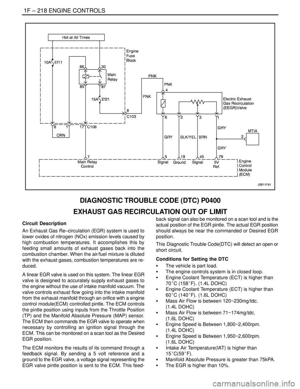
1F – 218IENGINE CONTROLS
DAEWOO V–121 BL4
DIAGNOSTIC TROUBLE CODE (DTC) P0400
EXHAUST GAS RECIRCULATION OUT OF LIMIT
Circuit Description
An Exhaust Gas Re–circulation (EGR) system is used to
lower oxides of nitrogen (NOx) emission levels caused by
high combustion temperatures. It accomplishes this by
feeding small amounts of exhaust gases back into the
combustion chamber. When the air/fuel mixture is diluted
with the exhaust gases, combustion temperatures are re-
duced.
A linear EGR valve is used on this system. The linear EGR
valve is designed to accurately supply exhaust gases to
the engine without the use of intake manifold vacuum. The
valve controls exhaust flow going into the intake manifold
from the exhaust manifold through an orifice with a engine
control module(ECM) controlled pintle. The ECM controls
the pintle position using inputs from the Throttle Position
(TP) and the Manifold Absolute Pressure (MAP) sensor.
The ECM then commands the EGR valve to operate when
necessary by controlling an ignition signal through the
ECM. This can be monitored on a scan tool as the Desired
EGR position.
The ECM monitors the results of its command through a
feedback signal. By sending a 5 volt reference and a
ground to the EGR valve, a voltage signal representing the
EGR valve pintle position is sent to the ECM. This feed-back signal can also be monitored on a scan tool and is the
actual position of the EGR pintle. The actual EGR position
should always be near the commanded or Desired EGR
position.
This Diagnostic Trouble Code(DTC) will detect an open or
short circuit.
Conditions for Setting the DTC
S The vehicle is part load.
S The engine controls system is in closed loop.
S Engine Coolant Temperature (ECT) is higher than
70°C (158°F). (1.4L DOHC)
S Engine Coolant Temperature (ECT) is higher than
60°C (140°F). (1.6L DOHC)
S Mass Air Flow is between 120~230mg/tdc.
(1.4L DOHC)
S Mass Air Flow is between 71~174mg/tdc.
(1.6L DOHC)
S Engine Speed is Between 1,800~2,400rpm.
(1.4L DOHC)
S Engine Speed is Between 1,950~2,600rpm.
(1.6L DOHC)
S Intake Air Temperature(IAT) is higher than
15°C(59°F).
S Manifold Absolute Pressure is greater than 75kPA.
S The EGR is higher than 10%.
Page 467 of 2643
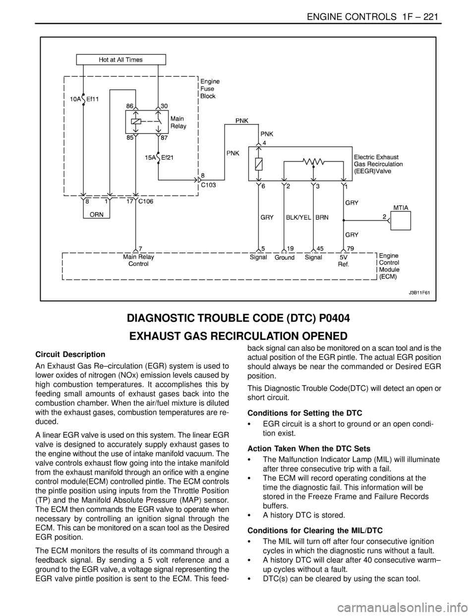
ENGINE CONTROLS 1F – 221
DAEWOO V–121 BL4
DIAGNOSTIC TROUBLE CODE (DTC) P0404
EXHAUST GAS RECIRCULATION OPENED
Circuit Description
An Exhaust Gas Re–circulation (EGR) system is used to
lower oxides of nitrogen (NOx) emission levels caused by
high combustion temperatures. It accomplishes this by
feeding small amounts of exhaust gases back into the
combustion chamber. When the air/fuel mixture is diluted
with the exhaust gases, combustion temperatures are re-
duced.
A linear EGR valve is used on this system. The linear EGR
valve is designed to accurately supply exhaust gases to
the engine without the use of intake manifold vacuum. The
valve controls exhaust flow going into the intake manifold
from the exhaust manifold through an orifice with a engine
control module(ECM) controlled pintle. The ECM controls
the pintle position using inputs from the Throttle Position
(TP) and the Manifold Absolute Pressure (MAP) sensor.
The ECM then commands the EGR valve to operate when
necessary by controlling an ignition signal through the
ECM. This can be monitored on a scan tool as the Desired
EGR position.
The ECM monitors the results of its command through a
feedback signal. By sending a 5 volt reference and a
ground to the EGR valve, a voltage signal representing the
EGR valve pintle position is sent to the ECM. This feed-back signal can also be monitored on a scan tool and is the
actual position of the EGR pintle. The actual EGR position
should always be near the commanded or Desired EGR
position.
This Diagnostic Trouble Code(DTC) will detect an open or
short circuit.
Conditions for Setting the DTC
S EGR circuit is a short to ground or an open condi-
tion exist.
Action Taken When the DTC Sets
S The Malfunction Indicator Lamp (MIL) will illuminate
after three consecutive trip with a fail.
S The ECM will record operating conditions at the
time the diagnostic fail. This information will be
stored in the Freeze Frame and Failure Records
buffers.
S A history DTC is stored.
Conditions for Clearing the MIL/DTC
S The MIL will turn off after four consecutive ignition
cycles in which the diagnostic runs without a fault.
S A history DTC will clear after 40 consecutive warm–
up cycles without a fault.
S DTC(s) can be cleared by using the scan tool.
Page 470 of 2643
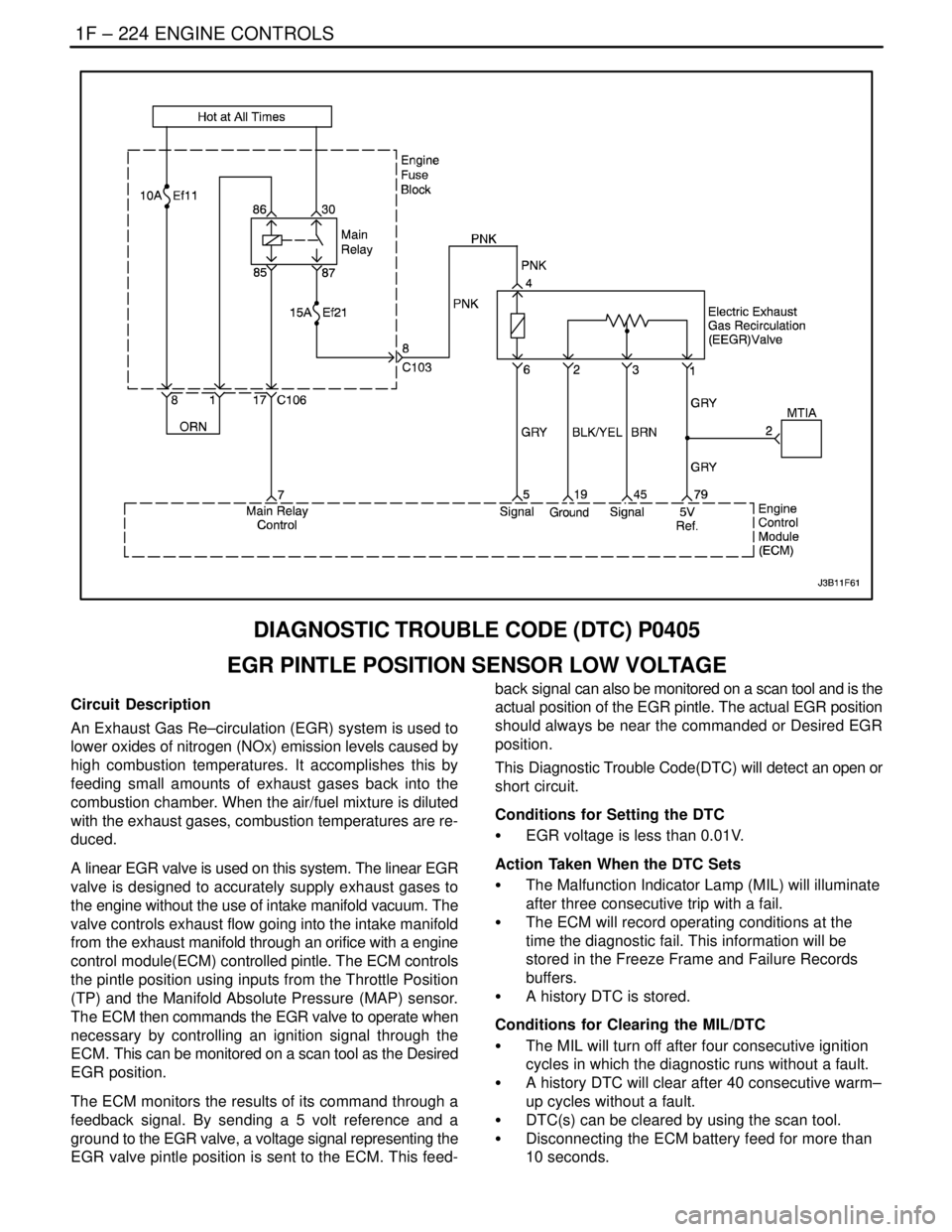
1F – 224IENGINE CONTROLS
DAEWOO V–121 BL4
DIAGNOSTIC TROUBLE CODE (DTC) P0405
EGR PINTLE POSITION SENSOR LOW VOLTAGE
Circuit Description
An Exhaust Gas Re–circulation (EGR) system is used to
lower oxides of nitrogen (NOx) emission levels caused by
high combustion temperatures. It accomplishes this by
feeding small amounts of exhaust gases back into the
combustion chamber. When the air/fuel mixture is diluted
with the exhaust gases, combustion temperatures are re-
duced.
A linear EGR valve is used on this system. The linear EGR
valve is designed to accurately supply exhaust gases to
the engine without the use of intake manifold vacuum. The
valve controls exhaust flow going into the intake manifold
from the exhaust manifold through an orifice with a engine
control module(ECM) controlled pintle. The ECM controls
the pintle position using inputs from the Throttle Position
(TP) and the Manifold Absolute Pressure (MAP) sensor.
The ECM then commands the EGR valve to operate when
necessary by controlling an ignition signal through the
ECM. This can be monitored on a scan tool as the Desired
EGR position.
The ECM monitors the results of its command through a
feedback signal. By sending a 5 volt reference and a
ground to the EGR valve, a voltage signal representing the
EGR valve pintle position is sent to the ECM. This feed-back signal can also be monitored on a scan tool and is the
actual position of the EGR pintle. The actual EGR position
should always be near the commanded or Desired EGR
position.
This Diagnostic Trouble Code(DTC) will detect an open or
short circuit.
Conditions for Setting the DTC
S EGR voltage is less than 0.01V.
Action Taken When the DTC Sets
S The Malfunction Indicator Lamp (MIL) will illuminate
after three consecutive trip with a fail.
S The ECM will record operating conditions at the
time the diagnostic fail. This information will be
stored in the Freeze Frame and Failure Records
buffers.
S A history DTC is stored.
Conditions for Clearing the MIL/DTC
S The MIL will turn off after four consecutive ignition
cycles in which the diagnostic runs without a fault.
S A history DTC will clear after 40 consecutive warm–
up cycles without a fault.
S DTC(s) can be cleared by using the scan tool.
S Disconnecting the ECM battery feed for more than
10 seconds.
Page 473 of 2643

ENGINE CONTROLS 1F – 227
DAEWOO V–121 BL4
DIAGNOSTIC TROUBLE CODE (DTC) P0406
EGR PINTLE POSITION SENSOR HIGH VOLTAGE
Circuit Description
An Exhaust Gas Re–circulation (EGR) system is used to
lower oxides of nitrogen (NOx) emission levels caused by
high combustion temperatures. It accomplishes this by
feeding small amounts of exhaust gases back into the
combustion chamber. When the air/fuel mixture is diluted
with the exhaust gases, combustion temperatures are re-
duced.
A linear EGR valve is used on this system. The linear EGR
valve is designed to accurately supply exhaust gases to
the engine without the use of intake manifold vacuum. The
valve controls exhaust flow going into the intake manifold
from the exhaust manifold through an orifice with a engine
control module(ECM) controlled pintle. The ECM controls
the pintle position using inputs from the Throttle Position
(TP) and the Manifold Absolute Pressure (MAP) sensor.
The ECM then commands the EGR valve to operate when
necessary by controlling an ignition signal through the
ECM. This can be monitored on a scan tool as the Desired
EGR position.
The ECM monitors the results of its command through a
feedback signal. By sending a 5 volt reference and a
ground to the EGR valve, a voltage signal representing the
EGR valve pintle position is sent to the ECM. This feed-back signal can also be monitored on a scan tool and is the
actual position of the EGR pintle. The actual EGR position
should always be near the commanded or Desired EGR
position.
This Diagnostic Trouble Code(DTC) will detect an open or
short circuit.
Conditions for Setting the DTC
S EGR voltage is higher than 4.99V.
Action Taken When the DTC Sets
S The Malfunction Indicator Lamp (MIL) will illuminate
after three consecutive trip with a fail.
S The ECM will record operating conditions at the
time the diagnostic fail. This information will be
stored in the Freeze Frame and Failure Records
buffers.
S A history DTC is stored.
Conditions for Clearing the MIL/DTC
S The MIL will turn off after four consecutive ignition
cycles in which the diagnostic runs without a fault.
S A history DTC will clear after 40 consecutive warm–
up cycles without a fault.
S DTC(s) can be cleared by using the scan tool.
S Disconnecting the ECM battery feed for more than
10 seconds.
Page 525 of 2643

ENGINE CONTROLS 1F – 279
DAEWOO V–121 BL4
DIAGNOSTIC TROUBLE CODE (DTC) P1181
VARIABLE INTAKE MANIFOLD SOLENOID LOW
VOLTAGE
Circuit Description
The Engine Control Module(ECM) operates a solenoid to
control the Variable Intake Manifold(VIM) solenoid electri-
cal. The solenoid is normally closed. By providing a ground
path, the ECM energizes the solenoid.
Conditions for Setting the DTC
S The VIM solenoid circuit is an open or a short to
ground condition exists.
Action Taken When the DTC Sets
S The Malfunction Indicator Lamp (MIL) will illumi-
nate.
S The ECM will record operating conditions at the
time the diagnostic fails. The information will be
stored in the freeze frame and failure records buff-
ers.S A history DTC is stored.
Conditions for Clearing the MIL/DTC
S The MIL will turn off after consecutive ignition
cycles in which the diagnostic runs without a fault.
S A history DTC will clear after 40 consecutive warm
up cycles without a fault.
S DTC(s) can be cleared by using the scan tool.
S Disconnecting the ECM battery feed for 10 sec-
onds.
Diagnostic Aids
An intermittent problem may be caused by a poor connec-
tion, rubbed–through wire insulation, or a wire that is bro-
ken inside the insulation.
Page 526 of 2643

1F – 280IENGINE CONTROLS
DAEWOO V–121 BL4
DTC P1181 – Variable Intake Manifold Solenoid Low Voltage
StepActionValue(s)YesNo
1Perform an On–Board Diagnostic (EOBD) System
Check.
Is the system check complete?–Go to Step 2Go to
”On–Board
Diagnostic Sys-
tem Check”
21. Turn the ignition switch to LOCK.
2. Disconnect the Variable Intake Manifold(VIM)
solenoid connector.
3. Measure the resistance of the VIM solenoid.
Does the resistance near the specified value?0 WGo to Step 3Go to Step 6
31. Disconnect the ignition relay connector.
2. Check for an open or a short to ground in the
wire between the VIM solenoid connector ter-
minal 2 and the engine connector terminal 13.
Is the problem found?–Go to Step 4Go to Step 5
4Repair the wire and the connector terminal.
Is the repair complete?–Go to Step 8–
51. Turn the ignition switch to LOCK.
2. Disconnect the Engine Control Module(ECM)
connector.
3. Check for an open or a short to ground in the
wire between the VIM solenoid connector ter-
minal 1 and the ECM connector terminal 37.
Is the problem found?–Go to Step 4Go to Step 7
6Replace the VIM solenoid.
Is the replacement complete?–Go to Step 8–
7Replace the ECM.
Is the replacement complete?–Go to Step 9–
81. Using the scan tool, clear the Diagnostic
Trouble Codes (DTCs).
2. Start the engine.
3. Run the engine until it reaches normal operat-
ing temperature at idle.
4. Operating the vehicle within the conditions for
setting this DTC as specified in the supporting
text.
Does the scan tool indicate that this diagnostic has
run and passed?–Go to Step 9Go to Step 2
9Check if any additional DTCs are set.
Are any DTCs displayed that have not been diag-
nosed?–Go to
applicable DTC
tableSystem OK
Page 527 of 2643

ENGINE CONTROLS 1F – 281
DAEWOO V–121 BL4
DIAGNOSTIC TROUBLE CODE (DTC) P1182
VARIABLE INTAKE MANIFOLD SOLENOID HIGH
VOLTAGE
Circuit Description
The Engine Control Module(ECM) operates a solenoid to
control the Variable Intake Manifold(VIM) solenoid electri-
cal. The solenoid is normally closed. By providing a ground
path, the ECM energizes the solenoid.
Conditions for Setting the DTC
S The VIM solenoid circuit is a short to battery condi-
tion exists.
Action Taken When the DTC Sets
S The Malfunction Indicator Lamp (MIL) will illumi-
nate.
S The ECM will record operating conditions at the
time the diagnostic fails. The information will be
stored in the freeze frame and failure records buff-
ers.S A history DTC is stored.
Conditions for Clearing the MIL/DTC
S The MIL will turn off after consecutive ignition
cycles in which the diagnostic runs without a fault.
S A history DTC will clear after 40 consecutive warm
up cycles without a fault.
S DTC(s) can be cleared by using the scan tool.
S Disconnecting the ECM battery feed for 10 sec-
onds.
Diagnostic Aids
An intermittent problem may be caused by a poor connec-
tion, rubbed–through wire insulation, or a wire that is bro-
ken inside the insulation.
Page 528 of 2643

1F – 282IENGINE CONTROLS
DAEWOO V–121 BL4
DTC P1182 – Variable Intake Manifold Solenoid High Voltage
StepActionValue(s)YesNo
1Perform an On–Board Diagnostic (EOBD) System
Check.
Is the system check complete?–Go to Step 2Go to
”On–Board
Diagnostic Sys-
tem Check”
21. Turn the ignition switch to LOCK.
2. Disconnect the Variable Intake Manifold(VIM)
solenoid connector.
3. Measure the resistance of the VIM solenoid.
Does the resistance near the specified value?0 WGo to Step 3Go to Step 6
31. Disconnect the ignition relay connector.
2. Check for a short to battery in the wire between
the VIM solenoid connector terminal 2 and the
engine connector terminal 13.
Is the problem found?–Go to Step 4Go to Step 5
4Repair the wire and the connector terminal.
Is the repair complete?–Go to Step 8–
51. Turn the ignition switch to LOCK.
2. Disconnect the Engine Control Module(ECM)
connector.
3. Check for a short to battery voltage in the wire
between the VIM solenoid connector terminal 1
and the ECM connector terminal 37.
Is the problem found?–Go to Step 4Go to Step 7
6Replace the VIM solenoid.
Is the replacement complete?–Go to Step 8–
7Replace the ECM.
Is the replacement complete?–Go to Step 9–
81. Using the scan tool, clear the Diagnostic
Trouble Codes (DTCs).
2. Start the engine.
3. Run the engine until it reaches normal operat-
ing temperature at idle.
4. Operating the vehicle within the conditions for
setting this DTC as specified in the supporting
text.
Does the scan tool indicate that this diagnostic has
run and passed?–Go to Step 9Go to Step 2
9Check if any additional DTCs are set.
Are any DTCs displayed that have not been diag-
nosed?–Go to
applicable DTC
tableSystem OK
Page 554 of 2643
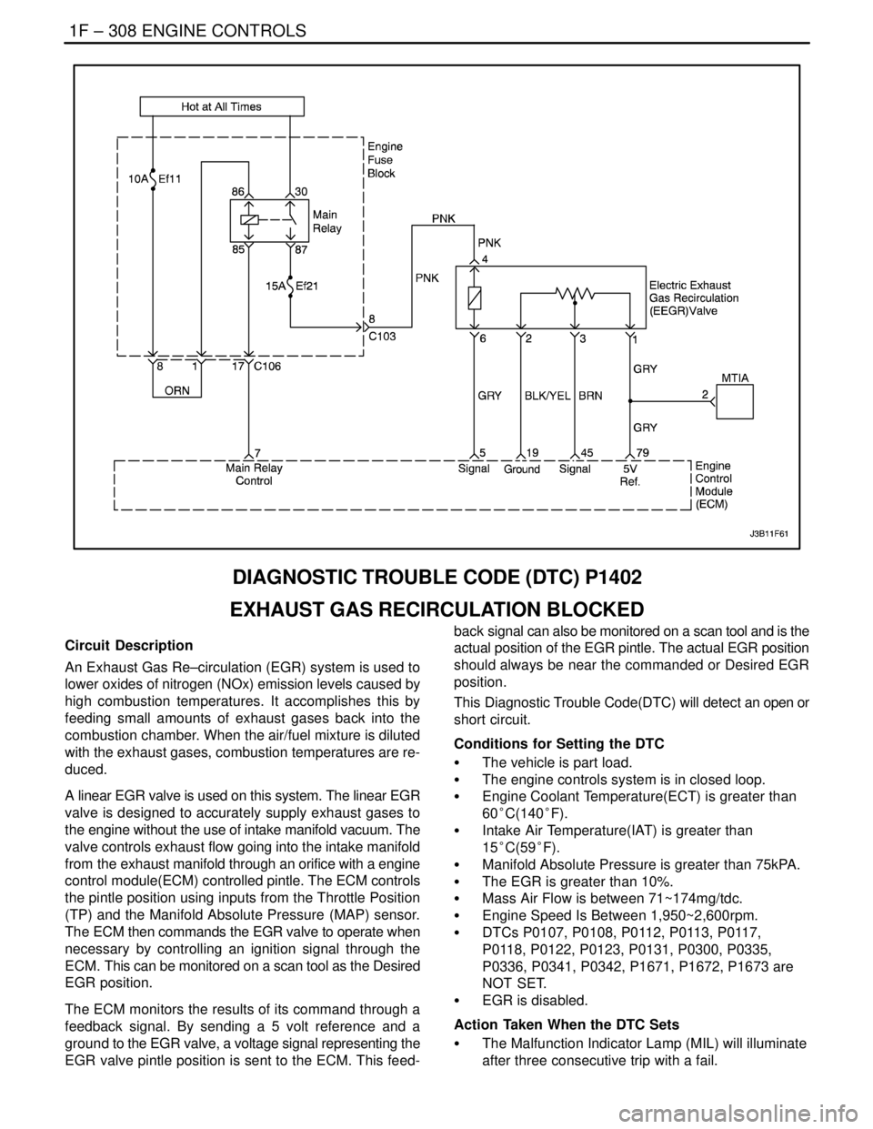
1F – 308IENGINE CONTROLS
DAEWOO V–121 BL4
DIAGNOSTIC TROUBLE CODE (DTC) P1402
EXHAUST GAS RECIRCULATION BLOCKED
Circuit Description
An Exhaust Gas Re–circulation (EGR) system is used to
lower oxides of nitrogen (NOx) emission levels caused by
high combustion temperatures. It accomplishes this by
feeding small amounts of exhaust gases back into the
combustion chamber. When the air/fuel mixture is diluted
with the exhaust gases, combustion temperatures are re-
duced.
A linear EGR valve is used on this system. The linear EGR
valve is designed to accurately supply exhaust gases to
the engine without the use of intake manifold vacuum. The
valve controls exhaust flow going into the intake manifold
from the exhaust manifold through an orifice with a engine
control module(ECM) controlled pintle. The ECM controls
the pintle position using inputs from the Throttle Position
(TP) and the Manifold Absolute Pressure (MAP) sensor.
The ECM then commands the EGR valve to operate when
necessary by controlling an ignition signal through the
ECM. This can be monitored on a scan tool as the Desired
EGR position.
The ECM monitors the results of its command through a
feedback signal. By sending a 5 volt reference and a
ground to the EGR valve, a voltage signal representing the
EGR valve pintle position is sent to the ECM. This feed-back signal can also be monitored on a scan tool and is the
actual position of the EGR pintle. The actual EGR position
should always be near the commanded or Desired EGR
position.
This Diagnostic Trouble Code(DTC) will detect an open or
short circuit.
Conditions for Setting the DTC
S The vehicle is part load.
S The engine controls system is in closed loop.
S Engine Coolant Temperature(ECT) is greater than
60°C(140°F).
S Intake Air Temperature(IAT) is greater than
15°C(59°F).
S Manifold Absolute Pressure is greater than 75kPA.
S The EGR is greater than 10%.
S Mass Air Flow is between 71~174mg/tdc.
S Engine Speed Is Between 1,950~2,600rpm.
S DTCs P0107, P0108, P0112, P0113, P0117,
P0118, P0122, P0123, P0131, P0300, P0335,
P0336, P0341, P0342, P1671, P1672, P1673 are
NOT SET.
S EGR is disabled.
Action Taken When the DTC Sets
S The Malfunction Indicator Lamp (MIL) will illuminate
after three consecutive trip with a fail.
Page 556 of 2643
1F – 310IENGINE CONTROLS
DAEWOO V–121 BL4
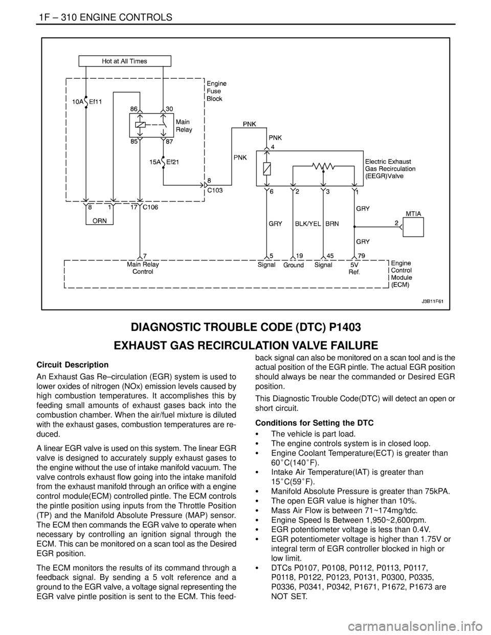
DIAGNOSTIC TROUBLE CODE (DTC) P1403
EXHAUST GAS RECIRCULATION VALVE FAILURE
Circuit Description
An Exhaust Gas Re–circulation (EGR) system is used to
lower oxides of nitrogen (NOx) emission levels caused by
high combustion temperatures. It accomplishes this by
feeding small amounts of exhaust gases back into the
combustion chamber. When the air/fuel mixture is diluted
with the exhaust gases, combustion temperatures are re-
duced.
A linear EGR valve is used on this system. The linear EGR
valve is designed to accurately supply exhaust gases to
the engine without the use of intake manifold vacuum. The
valve controls exhaust flow going into the intake manifold
from the exhaust manifold through an orifice with a engine
control module(ECM) controlled pintle. The ECM controls
the pintle position using inputs from the Throttle Position
(TP) and the Manifold Absolute Pressure (MAP) sensor.
The ECM then commands the EGR valve to operate when
necessary by controlling an ignition signal through the
ECM. This can be monitored on a scan tool as the Desired
EGR position.
The ECM monitors the results of its command through a
feedback signal. By sending a 5 volt reference and a
ground to the EGR valve, a voltage signal representing the
EGR valve pintle position is sent to the ECM. This feed-back signal can also be monitored on a scan tool and is the
actual position of the EGR pintle. The actual EGR position
should always be near the commanded or Desired EGR
position.
This Diagnostic Trouble Code(DTC) will detect an open or
short circuit.
Conditions for Setting the DTC
S The vehicle is part load.
S The engine controls system is in closed loop.
S Engine Coolant Temperature(ECT) is greater than
60°C(140°F).
S Intake Air Temperature(IAT) is greater than
15°C(59°F).
S Manifold Absolute Pressure is greater than 75kPA.
S The open EGR value is higher than 10%.
S Mass Air Flow is between 71~174mg/tdc.
S Engine Speed Is Between 1,950~2,600rpm.
S EGR potentiometer voltage is less than 0.4V.
S EGR potentiometer voltage is higher than 1.75V or
integral term of EGR controller blocked in high or
low limit.
S DTCs P0107, P0108, P0112, P0113, P0117,
P0118, P0122, P0123, P0131, P0300, P0335,
P0336, P0341, P0342, P1671, P1672, P1673 are
NOT SET.