intake manifold DAEWOO NUBIRA 2004 Service Service Manual
[x] Cancel search | Manufacturer: DAEWOO, Model Year: 2004, Model line: NUBIRA, Model: DAEWOO NUBIRA 2004Pages: 2643, PDF Size: 80.54 MB
Page 195 of 2643

1.8L DOHC ENGINE MECHANICAL 1C2 – 75
DAEWOO V–121 BL4
GENERAL DESCRIPTION
AND SYSTEM OPERATION
CYLINDER HEAD AND GASKET
The cylinder head is made of an aluminum alloy. The cylin-
der head uses cross–flow intake and exhaust ports. A
spark plug is located in the center of each combustion
chamber. The cylinder head houses the dual camshafts.
CRANKSHAFT
The crankshaft has eight integral weights which are cast
with it for balancing. Oil holes run through the center of the
crankshaft to supply oil to the connecting rods, the bear-
ings, the pistons, and the other components. The end
thrust load is taken by the thrust washers installed at the
center journal.
TIMING BELT
The timing belt coordinates the crankshaft and the dual
overhead camshafts and keeps them synchronized. The
timing belt also turns the coolant pump. The timing belt
and the pulleys are toothed so that there is no slippage be-
tween them. There are two idler pulleys. An automatic ten-
sioner pulley maintains the timing belt’s correct tension.
The timing belt is made of a tough reinforced rubber similar
to that used on the serpentine drive belt. The timing belt
requires no lubrication.
OIL PUMP
The oil pump draws engine oil from the oil pan and feeds
it under pressure to the various parts of the engine. An oil
strainer is mounted before the inlet of the oil pump to re-
move impurities which could clog or damage the oil pump
or other engine components. When the crankshaft ro-
tates, the oil pump driven gear rotates. This causes the
space between the gears to constantly open and narrow,
pulling oil in from the oil pan when the space opens and
pumping the oil out to the engine as it narrows.
At high engine speeds, the oil pump supplies a much high-
er amount of oil than required for lubrication of the engine.
The oil pressure regulator prevents too much oil from en-
tering the engine lubrication passages. During normal oil
supply, a coil spring and valve keep the bypass closed, di-
recting all of the oil pumped to the engine. When the
amount of oil being pumped increases, the pressure be-
comes high enough to overcome the force of the spring.This opens the valve of the oil pressure regulator, allowing
the excess oil to flow through the valve and drain back to
the oil pan.
OIL PAN
The engine oil pan is mounted to the bottom of the cylinder
block. The engine oil pan houses the crankcase and is
made of cast aluminum.
Engine oil is pumped from the oil pan by the oil pump. After
it passes through the oil filter, it is fed through two paths
to lubricate the cylinder block and cylinder head. In one
path, the oil is pumped through oil passages in the crank-
shaft to the connecting rods, then to the pistons and cylin-
ders. It then drains back to the oil pan. In the second path,
the oil is pumped through passages to the camshaft. The
oil passes through the internal passageways in the cam-
shafts to lubricate the valve assemblies before draining
back to the oil pan.
EXHAUST MANIFOLD
A single four–port, rear–takedown manifold is used with
this engine. The manifold is designed to direct escaping
exhaust gases out of the combustion chambers with a
minimum of back pressure. The oxygen sensor is
mounted to the exhaust manifold.
INTAKE MANIFOLD
The intake manifold has four independent long ports and
utilizes an inertial supercharging effect to improve engine
torque at low and moderate speeds.
CAMSHAFTS
This engine is a dual overhead camshaft (DOHC) type,
which means there are two camshafts. One camshaft op-
erates the intake valves, and the other camshaft operates
the exhaust valves. The camshafts sit in journals on the
top of the engine (in the cylinder head) and are held in
place by camshaft caps. The camshaft journals of the cyl-
inder head are drilled for oil passages. Engine oil travels
to the camshafts under pressure where it lubricates each
camshaft journal. The oil returns to the oil pan through
drain holes in the cylinder head. The camshaft lobes are
machined into the solid camshaft to precisely open and
close the intake and the exhaust valves the correct
amount at the correct time. The camshaft lobes are oiled
by splash action from pressurized oil escaping from the
camshaft journals.
Page 199 of 2643

1D – 4IENGINE COOLING
DAEWOO V–121 BL4
COOLING SYSTEM DIAGNOSIS
Engine Overheats
ChecksAction
Check for a loss of the coolant.Add the coolant.
Check for a weak coolant solution.Confirm that the coolant solution is a 50/50 mixture of eth-
ylene glycol and water.
Check the front of the radiator for any dirt, any leaves, or
any insects.Clean the front of the radiator.
Check for leakage from the hoses, the coolant pump, the
heater, the thermostat housing, the radiator, the core
plugs, or the head gasket.Replace any damaged components.
Check for a faulty thermostat.Replace a damaged thermostat.
Check for retarded ignition timing.Perform an ECM code diagnosis. Confirm the integrity of
the timing belt.
Check for an improperly operating electric cooling fan.Replace the electric cooling fan.
Check for radiator hoses that are plugged or rotted.Replace any damaged radiator hoses.
Check for a faulty water pump.Replace a faulty water pump.
Check for a faulty surge tank cap.Replace a faulty surge tank cap.
Check for a cylinder head or an engine block that is
cracked or plugged.Repair the damaged cylinder head or the damaged engine
block.
Loss of Coolant
ChecksAction
Check for a leak in the radiator.Replace a damaged radiator.
Check for a leak in the following locations:
S Surge tank.
S Hose.Replace the following parts, as needed:
S Surge tank.
S Hose.
Check for loose or damaged radiator hoses, heater hoses,
and connections.Reseat the hoses.
Replace the hoses or the clamps.
Check for leaks in the coolant pump seal.Replace the coolant pump seal.
Check for leaks in the coolant pump gasket.Replace the coolant pump gasket.
Check for an improper cylinder head torque.Tighten the cylinder head bolts to specifications.
Replace the cylinder head gasket, if needed.
Check for leaks in the following locations:
S Intake manifold.
S Cylinder head gasket.
S Cylinder block plug.
S Heater core.
S Radiator drain plug.Repair or replace any components, as needed, to correct
the leak.
Engine Fails to Reach Normal Operating Temperature or Cool Air
from the Heater
ChecksAction
Check to determine if the thermostat is stuck open or is the
wrong type of thermostat.Install a new thermostat of the correct type and heat range.
Check the coolant level to determine if it is below the MIN
mark on the surge tank.Add sufficient coolant to raise the fluid to the specified
mark on the surge tank.
Page 217 of 2643

ENGINE ELECTRICAL 1E – 3
DAEWOO V–121 BL4
FASTENER TIGHTENING SPECIFICATIONS
ApplicationNSmLb–FtLb–In
Battery Cable Nuts5–44
Battery Carrier Tray Lower, Side and Upper Bolts2015–
Battery Retainer Clamp–to–Battery Rod Nuts5–44
Generator Drive End Bearing Nut8160–
Generator Lower Bracket–to–Engine Block Bolts (1.8L Engine)3727–
Generator Lower Bracket–to–Generator Nut (1.4L/1.6L Engine)2518–
Generator Through–Bolts10–89
Generator–to–Intake Manifold and Cylinder Head Support
Bracket Bolts (1.8L Engine)3727–
Generator–to–Intake Manifold Strap Bracket Bolt (1.8L Engine)2216–
Generator Upper Support Bracket Bolt (1.4L/1.6L Engine)2015–
Intake Manifold–to–Cylinder Body Strap Bracket Bolts (Over
Starter)2216–
Starter Field Connector Nut12–106
Starter Lower Mounting Stud Ground Wire Nut12–106
Starter Mounting Studs/Nuts (1.4L/1.6L Engine)2518–
Starter Solenoid Assembly Screws8–71
Starter Solenoid Terminal–to–Battery Cable Terminal Nut5.5–49
Starter Solenoid Terminal–to–Ignition Solenoid Terminal Nut5.5–49
Starter Through–Bolts6–53
Starter–to–Engine Block Mounting Bolt (1.8L Engine)4533–
Starter–to–Engine Transaxle Mounting Bolt (1.8L Engine)5037–
Page 225 of 2643
ENGINE ELECTRICAL 1E – 11
DAEWOO V–121 BL4
MAINTENANCE AND REPAIR
ON–VEHICLE SERVICE
GENERATOR
Removal Procedure
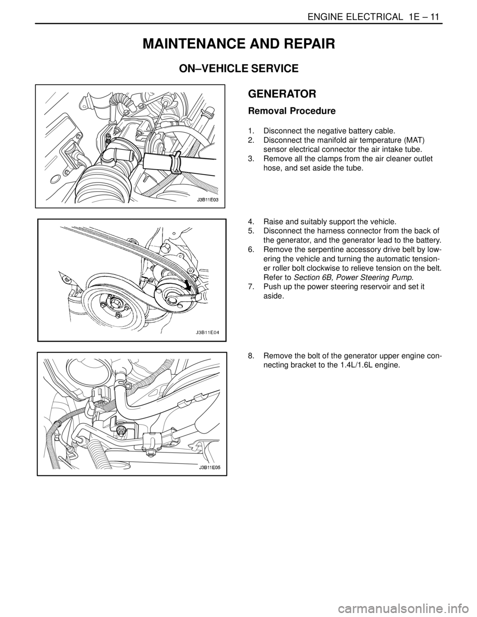
1. Disconnect the negative battery cable.
2. Disconnect the manifold air temperature (MAT)
sensor electrical connector the air intake tube.
3. Remove all the clamps from the air cleaner outlet
hose, and set aside the tube.
4. Raise and suitably support the vehicle.
5. Disconnect the harness connector from the back of
the generator, and the generator lead to the battery.
6. Remove the serpentine accessory drive belt by low-
ering the vehicle and turning the automatic tension-
er roller bolt clockwise to relieve tension on the belt.
Refer to Section 6B, Power Steering Pump.
7. Push up the power steering reservoir and set it
aside.
8. Remove the bolt of the generator upper engine con-
necting bracket to the 1.4L/1.6L engine.
Page 226 of 2643
1E – 12IENGINE ELECTRICAL
DAEWOO V–121 BL4
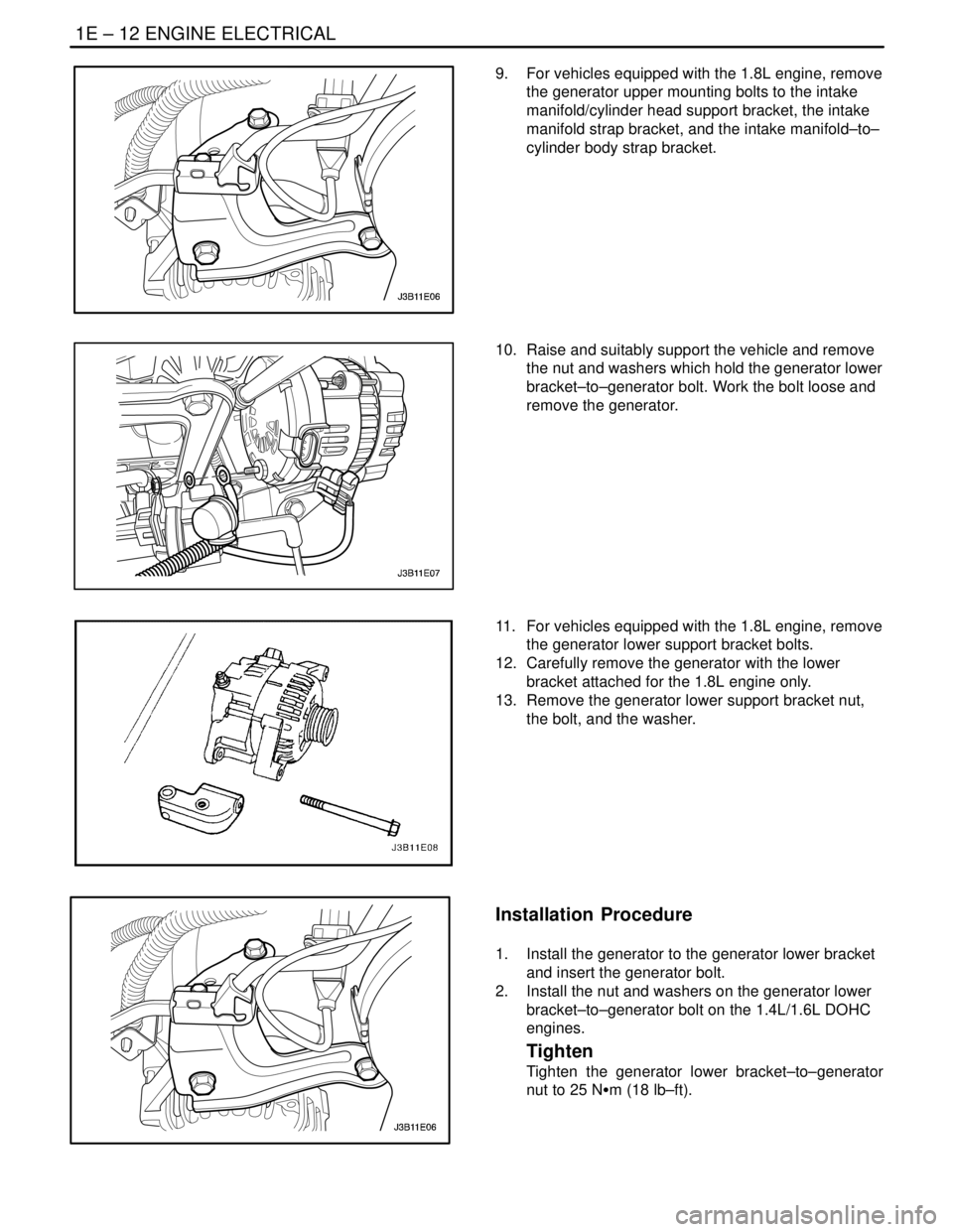
9. For vehicles equipped with the 1.8L engine, remove
the generator upper mounting bolts to the intake
manifold/cylinder head support bracket, the intake
manifold strap bracket, and the intake manifold–to–
cylinder body strap bracket.
10. Raise and suitably support the vehicle and remove
the nut and washers which hold the generator lower
bracket–to–generator bolt. Work the bolt loose and
remove the generator.
11. For vehicles equipped with the 1.8L engine, remove
the generator lower support bracket bolts.
12. Carefully remove the generator with the lower
bracket attached for the 1.8L engine only.
13. Remove the generator lower support bracket nut,
the bolt, and the washer.
Installation Procedure
1. Install the generator to the generator lower bracket
and insert the generator bolt.
2. Install the nut and washers on the generator lower
bracket–to–generator bolt on the 1.4L/1.6L DOHC
engines.
Tighten
Tighten the generator lower bracket–to–generator
nut to 25 NSm (18 lb–ft).
Page 227 of 2643
ENGINE ELECTRICAL 1E – 13
DAEWOO V–121 BL4
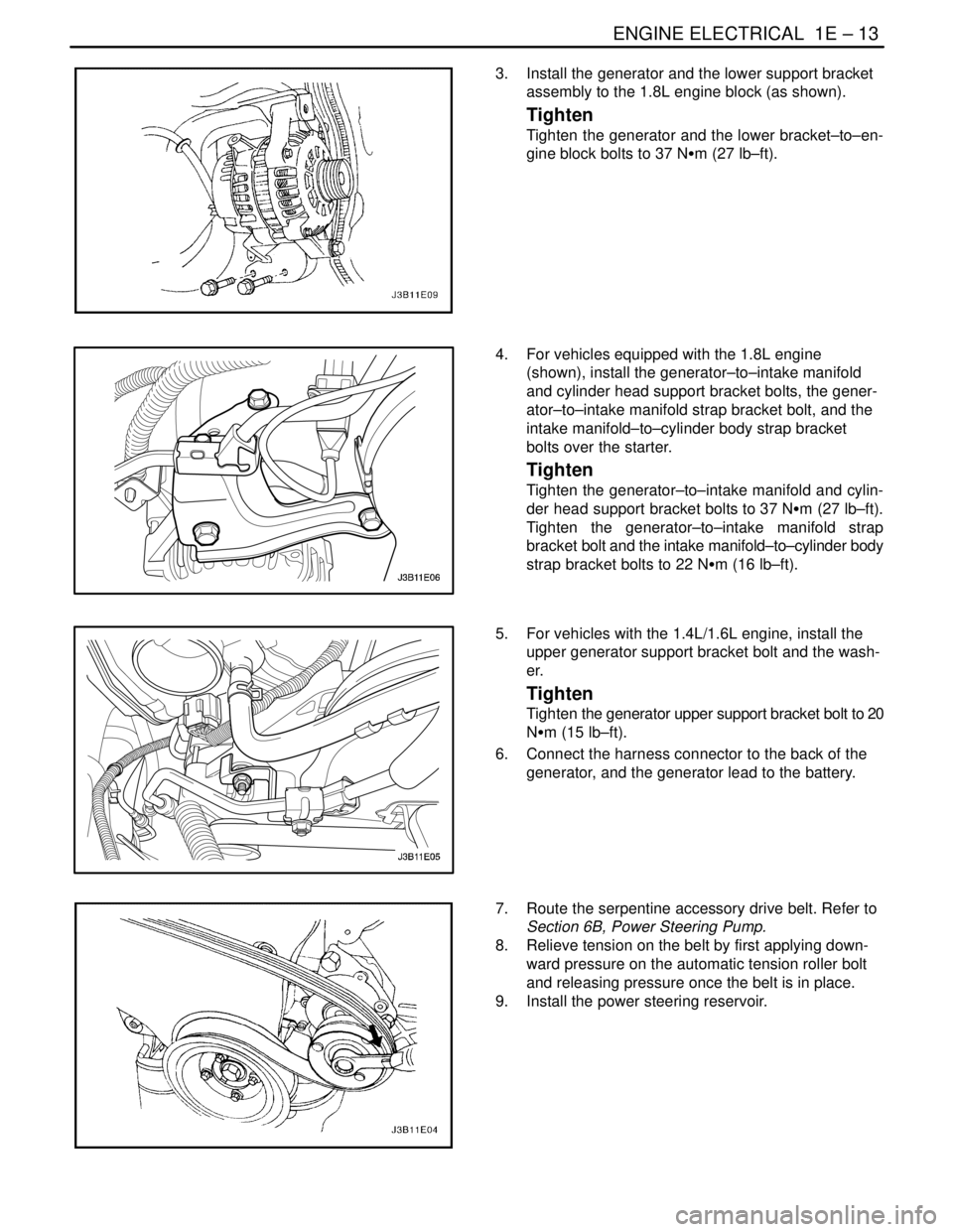
3. Install the generator and the lower support bracket
assembly to the 1.8L engine block (as shown).
Tighten
Tighten the generator and the lower bracket–to–en-
gine block bolts to 37 NSm (27 lb–ft).
4. For vehicles equipped with the 1.8L engine
(shown), install the generator–to–intake manifold
and cylinder head support bracket bolts, the gener-
ator–to–intake manifold strap bracket bolt, and the
intake manifold–to–cylinder body strap bracket
bolts over the starter.
Tighten
Tighten the generator–to–intake manifold and cylin-
der head support bracket bolts to 37 NSm (27 lb–ft).
Tighten the generator–to–intake manifold strap
bracket bolt and the intake manifold–to–cylinder body
strap bracket bolts to 22 NSm (16 lb–ft).
5. For vehicles with the 1.4L/1.6L engine, install the
upper generator support bracket bolt and the wash-
er.
Tighten
Tighten the generator upper support bracket bolt to 20
NSm (15 lb–ft).
6. Connect the harness connector to the back of the
generator, and the generator lead to the battery.
7. Route the serpentine accessory drive belt. Refer to
Section 6B, Power Steering Pump.
8. Relieve tension on the belt by first applying down-
ward pressure on the automatic tension roller bolt
and releasing pressure once the belt is in place.
9. Install the power steering reservoir.
Page 248 of 2643

1F – 2IENGINE CONTROLS
DAEWOO V–121 BL4
TROUBLE CODE DIAGNOSIS
(1.4L/1.6L DOHC) 1F–111. . . . . . . . . . . . . . . . . . . . . . . .
Clearing Trouble Codes 1F–111. . . . . . . . . . . . . . . . . . . .
Diagnostic Trouble Codes (1.4L/1.6L DOHC) 1F–111.
DTC P0107 Manifold Absolute Pressure Sensor
Low Voltage 1F–114. . . . . . . . . . . . . . . . . . . . . . . . . . .
DTC P0108 Manifold Absolute Pressure Sensor
High Voltage 1F–117. . . . . . . . . . . . . . . . . . . . . . . . . .
DTC P0112 Intake Air Temperature Sensor Low
Voltage 1F–120. . . . . . . . . . . . . . . . . . . . . . . . . . . . . . .
DTC P0113 Intake Air Temperature Sensor High
Voltage 1F–122. . . . . . . . . . . . . . . . . . . . . . . . . . . . . . .
DTC P0117 Engine Coolant Temperature
Sensor Low Voltage 1F–125. . . . . . . . . . . . . . . . . . . .
DTC P0118 Engine Coolant Temperature
Sensor High Voltage 1F–128. . . . . . . . . . . . . . . . . . . .
DTC P0122 Throttle Position Sensor Low
Voltage 1F–131. . . . . . . . . . . . . . . . . . . . . . . . . . . . . . .
DTC P0123 Throttle Position Sensor High
Voltage 1F–134. . . . . . . . . . . . . . . . . . . . . . . . . . . . . . .
DTC P0131 Front Heated Oxygen Sensor Low
Voltage 1F–137. . . . . . . . . . . . . . . . . . . . . . . . . . . . . . .
DTC P0132 Front Heated Oxygen Sensor High
Voltage 1F–140. . . . . . . . . . . . . . . . . . . . . . . . . . . . . . .
DTC P0133 Front Heated Oxygen Sensor No
Activity 1F–142. . . . . . . . . . . . . . . . . . . . . . . . . . . . . . .
DTC P0135 Front Heated Oxygen Sensor Heater
Circuit Not Functioning 1F–145. . . . . . . . . . . . . . . . . .
DTC P0137 Rear Heated Oxygen Sensor Low
Voltage 1F–148. . . . . . . . . . . . . . . . . . . . . . . . . . . . . . .
DTC P0138 Rear Heated Oxygen Sensor High
Voltage 1F–151. . . . . . . . . . . . . . . . . . . . . . . . . . . . . . .
DTC P0140 Rear Heated Oxygen Sensor No
Activity 1F–153. . . . . . . . . . . . . . . . . . . . . . . . . . . . . . .
DTC P0141 Rear Heated Oxygen Sensor Heater
Malfunction 1F–156. . . . . . . . . . . . . . . . . . . . . . . . . . .
DTC P0171 Fuel Trim System Too Lean 1F–158. . . .
DTC P0172 Fuel Trim System Too Rich 1F–162. . . . .
DTC P0222 Main Throttle Idle Actuator (MTIA)
Low Voltage 1F–165. . . . . . . . . . . . . . . . . . . . . . . . . . .
DTC P0223 Main Throttle Idle Actuator (MTIA)
High Voltage 1F–168. . . . . . . . . . . . . . . . . . . . . . . . . .
DTC P0261 Injector 1 Low Voltage 1F–171. . . . . . . . .
DTC P0262 Injector 1 High Voltage 1F–173. . . . . . . .
DTC P0264 Injector 2 Low Voltage 1F–175. . . . . . . . .
DTC P0265 Injector 2 High Voltage 1F–177. . . . . . . .
DTC P0267 Injector 3 Low Voltage 1F–179. . . . . . . . .
DTC P0268 Injector 3 High Voltage 1F–181. . . . . . . .
DTC P0270 Injector 4 Low Voltage 1F–183. . . . . . . . .
DTC P0271 Injector 4 High Voltage 1F–185. . . . . . . . DTC P0300 Multiple Cylinder Misfire(Catalyst
Damage) 1F–188. . . . . . . . . . . . . . . . . . . . . . . . . . . . .
DTC P0300 Multiple Cylinder Misfire(Increase
Emission) 1F–192. . . . . . . . . . . . . . . . . . . . . . . . . . . . .
DTC P0327 Knock Sensor Circuit Fault
(1.4L DOHC) 1F–195. . . . . . . . . . . . . . . . . . . . . . . . . .
DTC P0327 Knock Sensor Circuit Fault
(1.6L DOHC) 1F–198. . . . . . . . . . . . . . . . . . . . . . . . . .
DTC P0335 Magnetic Crankshaft Position
Sensor Electrical Error 1F–201. . . . . . . . . . . . . . . . . .
DTC P0336 58X Crankshaft Position Sensor
No Plausible Signal 1F–204. . . . . . . . . . . . . . . . . . . .
DTC P0337 58X Crankshaft Position Sensor
No Signal 1F–207. . . . . . . . . . . . . . . . . . . . . . . . . . . . .
DTC P0341 Camshaft Position Sensor
Rationality 1F–210. . . . . . . . . . . . . . . . . . . . . . . . . . . .
DTC P0342 Camshaft Position Sensor Signal 1F–212
DTC P0351 Ignition Signal Coil A Fault 1F–214. . . . .
DTC P0352 Ignition Signal Coil B Fault 1F–216. . . . .
DTC P0400 Exhaust Gas Recirculation Out
Of Limit 1F–218. . . . . . . . . . . . . . . . . . . . . . . . . . . . . . .
DTC P0404 Exhaust Gas Recirculation
Opened 1F–221. . . . . . . . . . . . . . . . . . . . . . . . . . . . . . .
DTC P0405 EGR Pintle Position Sensor Low
Voltage 1F–224. . . . . . . . . . . . . . . . . . . . . . . . . . . . . . .
DTC P0406 EGR Pintle Position Sensor High
Voltage 1F–227. . . . . . . . . . . . . . . . . . . . . . . . . . . . . . .
DTC P0420 Catalyst Low Efficiency 1F–230. . . . . . . .
DTC P0444 EVAP Purge Control Circuit No
Signal 1F–232. . . . . . . . . . . . . . . . . . . . . . . . . . . . . . . .
DTC P0445 EVAP Purge Control Circuit Fault 1F–235
DTC P0462 Fuel Level Sensor Low Voltage
(1.6L DOHC Only) 1F–238. . . . . . . . . . . . . . . . . . . . .
DTC P0463 Fuel Level Sensor High Voltage
(1.6L DOHC Only) 1F–241. . . . . . . . . . . . . . . . . . . . .
DTC P0480 Low Speed Cooling Fan Relay
Circuit Fault (1.4L DOHC) 1F–245. . . . . . . . . . . . . . .
DTC P0480 Low Speed Cooling Fan Relay
Circuit Fault (1.6L DOHC) 1F–248. . . . . . . . . . . . . . .
DTC P0481 High Speed Cooling Fan Relay
Circuit Fault (1.4L DOHC) 1F–251. . . . . . . . . . . . . . .
DTC P0481 High Speed Cooling Fan Relay
Circuit Fault (1.6L DOHC) 1F–254. . . . . . . . . . . . . . .
DTC P0501 Vehicle Speed No Signal
(M/T Only) 1F–257. . . . . . . . . . . . . . . . . . . . . . . . . . . .
DTC P0510 Throttle Position Switch Circuit Fault
(1.4L DOHC) 1F–260. . . . . . . . . . . . . . . . . . . . . . . . . .
DTC P0510 Throttle Position Switch Circuit
Fault (1.6L DOHC) 1F–262. . . . . . . . . . . . . . . . . . . . .
DTC P0532 A/C Pressure Sensor Low Voltage 1F–264
DTC P0533 A/C Pressure Sensor High
Voltage 1F–267. . . . . . . . . . . . . . . . . . . . . . . . . . . . . . .
Page 249 of 2643

ENGINE CONTROLS 1F – 3
DAEWOO V–121 BL4
DTC P0562 System Voltage(Engine Side) Too
Low 1F–270. . . . . . . . . . . . . . . . . . . . . . . . . . . . . . . . . .
DTC P0563 System Voltage(Engine Side) Too
High 1F–272. . . . . . . . . . . . . . . . . . . . . . . . . . . . . . . . . .
DTC P0601 Engine Control Module Checksum
Error 1F–274. . . . . . . . . . . . . . . . . . . . . . . . . . . . . . . . .
DTC P0604 Engine Control Module Internal/External
RAM Error 1F–275. . . . . . . . . . . . . . . . . . . . . . . . . . . .
DTC P0605 Engine Control Module INMVY Write
Error 1F–276. . . . . . . . . . . . . . . . . . . . . . . . . . . . . . . . .
DTC P0656 Fuel Level Gauge Circuit Fault 1F–277. .
DTC P1181 Variable Intake Manifold Solenoid
Low Voltage 1F–279. . . . . . . . . . . . . . . . . . . . . . . . . . .
DTC P1182 Variable Intake Manifold Solenoid
High Voltage 1F–281. . . . . . . . . . . . . . . . . . . . . . . . . .
DTC P1230 Fuel Pump Relay Low Voltage
(1.4L DOHC) 1F–283. . . . . . . . . . . . . . . . . . . . . . . . . .
DTC P1230 Fuel Pump Relay Low Voltage
(1.6L DOHC) 1F–286. . . . . . . . . . . . . . . . . . . . . . . . . .
DTC P1231 Fuel Pump Relay High Voltage
(1.4L DOHC) 1F–289. . . . . . . . . . . . . . . . . . . . . . . . . .
DTC P1231 Fuel Pump Relay High Voltage
(1.6L DOHC) 1F–292. . . . . . . . . . . . . . . . . . . . . . . . . .
DTC P1320 Crankshaft Segment Period
Segment Adaptation At Limit 1F–295. . . . . . . . . . . .
DTC P1321 Crankshaft Segment Period Tooth
Error 1F–297. . . . . . . . . . . . . . . . . . . . . . . . . . . . . . . . .
DTC P1382 Rough Road Data Invalid
(NON ABS) 1F–299. . . . . . . . . . . . . . . . . . . . . . . . . . .
DTC P1382 Rough Road Data Invalid (ABS) 1F–302
DTC P1385 Rough Road Sensor Circuit Fault
(NON ABS) 1F–305. . . . . . . . . . . . . . . . . . . . . . . . . . .
DTC P1402 Exhaust Gas Recirculation
Blocked 1F–308. . . . . . . . . . . . . . . . . . . . . . . . . . . . . . .
DTC P1403 Exhaust Gas Recirculation Valve
Failure 1F–310. . . . . . . . . . . . . . . . . . . . . . . . . . . . . . . .
DTC P1404 Exhaust Gas Recirculation Closed1F–313
DTC P1511 Idle Charge Actuator Circuit Fault 1F–316
DTC P1512 Idle Charge Actuator Mechanical
Error 1F–319. . . . . . . . . . . . . . . . . . . . . . . . . . . . . . . . .
DTC P1513 Idle Charge Actuator Functional
Error 1F–321. . . . . . . . . . . . . . . . . . . . . . . . . . . . . . . . .
DTC P1537 A/C Compressor Relay High
Voltage 1F–324. . . . . . . . . . . . . . . . . . . . . . . . . . . . . . .
DTC P1538 A/C Compressor Relay Low
Voltage 1F–326. . . . . . . . . . . . . . . . . . . . . . . . . . . . . . .
DTC P1610 Main Relay High Voltage
(1.4L DOCH) 1F–328. . . . . . . . . . . . . . . . . . . . . . . . . .
DTC P1610 Main Relay High Voltage
(1.6L DOHC) 1F–330. . . . . . . . . . . . . . . . . . . . . . . . . .
DTC P1611 Main Relay Low Voltage
(1.4L DOHC) 1F–332. . . . . . . . . . . . . . . . . . . . . . . . . . DTC P1611 Main Relay Low Voltage
(1.6L DOHC) 1F–334. . . . . . . . . . . . . . . . . . . . . . . . . .
DTC P1628 Immobilizer No Successful
Communication 1F–336. . . . . . . . . . . . . . . . . . . . . . . .
DTC P1629 Immobilizer Wrong Computation 1F–338
DTC P1660 Malfunction Indicator Lamp (MIL)
High Voltage 1F–340. . . . . . . . . . . . . . . . . . . . . . . . . .
DTC P1661 Malfunction Indicator Lamp (MIL)
Low Voltage 1F–342. . . . . . . . . . . . . . . . . . . . . . . . . . .
TROUBLE CODE DIAGNOSIS (1.8L DOHC) 1F–344.
Clearing Trouble Codes 1F–344. . . . . . . . . . . . . . . . . . .
Diagnostic Trouble Codes (1.8L DOHC) 1F–344. . . .
DTC P0106 Manifold Absolute Pressure
Rationality 1F–347. . . . . . . . . . . . . . . . . . . . . . . . . . . .
DTC P0107 Manifold Absolut Pressure Low
Voltage 1F–349. . . . . . . . . . . . . . . . . . . . . . . . . . . . . . .
DTC P0108 Manifold Absolut Pressure High
Voltage 1F–352. . . . . . . . . . . . . . . . . . . . . . . . . . . . . . .
DTC P0112 Intake Air Temperature Low
Voltage 1F–355. . . . . . . . . . . . . . . . . . . . . . . . . . . . . . .
DTC P0113 Intake Air Temperature High
Voltage 1F–358. . . . . . . . . . . . . . . . . . . . . . . . . . . . . . .
DTC P0117 Engine Coolant Temperature Low
Voltage 1F–361. . . . . . . . . . . . . . . . . . . . . . . . . . . . . . .
DTC P0118 Engine Coolant Temperature High
Voltage 1F–363. . . . . . . . . . . . . . . . . . . . . . . . . . . . . . .
DTC P0122 Throttle Position Sensor Low
Voltage 1F–366. . . . . . . . . . . . . . . . . . . . . . . . . . . . . . .
DTC P0123 Throttle Position Sensor High
Voltage 1F–369. . . . . . . . . . . . . . . . . . . . . . . . . . . . . . .
DTC P0131 Front Heated Oxygen Sensor
(HO2S1) Low Voltage 1F–372. . . . . . . . . . . . . . . . . .
DTC P0132 Front Heated Oxygen Sensor
(HO2S1) High Voltage 1F–375. . . . . . . . . . . . . . . . . .
DTC P0133 Front Heated Oxygen Sensor
(HO2S1) Slow Response 1F–378. . . . . . . . . . . . . . .
DTC P0134 Front Heated Oxygen Sensor
(HO2S1) No Activity or Open 1F–382. . . . . . . . . . . .
DTC P0135 Front Heated Oxygen Sensor
(HO2S1) Heater Circuit Not Functioning 1F–385. . .
DTC P0137 Rear Heated Oxygen Sensor
(HO2S2) Low Voltage 1F–388. . . . . . . . . . . . . . . . . .
DTC P0138 Rear Heated Oxygen Sensor
(HO2S2) High Voltage 1F–391. . . . . . . . . . . . . . . . . .
DTC P0140 Rear Heated Oxygen Sensor
(HO2S2) No Activity or Open 1F–394. . . . . . . . . . . .
DTC P0141 Rear Heated Oxygen Sensor
(HO2S2) Heater Circuit Not Functioning 1F–397. . .
DTC P0171 Fuel Trim System Too Lean 1F–400. . . .
DTC P0172 Fuel Trim System Too Rich 1F–404. . . . .
DTC P0201 Injector 1 Circuit Fault 1F–408. . . . . . . . .
DTC P0202 Injector 2 Circuit Fault 1F–411. . . . . . . . .
Page 250 of 2643

1F – 4IENGINE CONTROLS
DAEWOO V–121 BL4
DTC P0203 Injector 3 Circuit Fault 1F–414. . . . . . . . .
DTC P0204 Injector 4 Circuit Fault 1F–417. . . . . . . . .
DTC P0300 Multiple Cylinder Misfire Detected 1F–421
DTC P0301 Cylinder 1 Misfire 1F–426. . . . . . . . . . . . .
DTC P0302 Cylinder 2 Misfire 1F–431. . . . . . . . . . . . .
DTC P0303 Cylinder 3 Misfire 1F–436. . . . . . . . . . . . .
DTC P0304 Cylinder 4 Misfire 1F–441. . . . . . . . . . . . .
DTC P0317 Rough Road Sensor Source Not
Detected 1F–445. . . . . . . . . . . . . . . . . . . . . . . . . . . . . .
DTC P0325 Knock Sensor Internal
Malfunction 1F–447. . . . . . . . . . . . . . . . . . . . . . . . . . .
DTC P0327 Knock Sensor Circuit Fault 1F–449. . . . .
DTC P0336 58X Crank Position Extra/Missing
Pulses 1F–452. . . . . . . . . . . . . . . . . . . . . . . . . . . . . . . .
DTC P0337 58X Crank Position Sensor No
Signal 1F–455. . . . . . . . . . . . . . . . . . . . . . . . . . . . . . . .
DTC P0341 Camshaft Position Sensor
Rationality 1F–458. . . . . . . . . . . . . . . . . . . . . . . . . . . .
DTC P0342 Camshaft Position Sensor No
Signal 1F–461. . . . . . . . . . . . . . . . . . . . . . . . . . . . . . . .
DTC P0351 Ignition Control Circuit A Fault
(Cylinder 1 and 4) 1F–464. . . . . . . . . . . . . . . . . . . . . .
DTC P0352 Ignition Control Circuit B Fault
(Cylinder 2 and 3) 1F–466. . . . . . . . . . . . . . . . . . . . . .
DTC P0401 Exhaust Gas Recirculation Insufficient
Flow 1F–468. . . . . . . . . . . . . . . . . . . . . . . . . . . . . . . . .
DTC P0402 Exhaust Gas Recirculation Excessive
Flow 1F–470. . . . . . . . . . . . . . . . . . . . . . . . . . . . . . . . .
DTC P0404 Exhaust Gas Recirculation Open
Valve Position Error 1F–474. . . . . . . . . . . . . . . . . . . .
DTC P0405 Exhaust Gas Recirculation Pintle
Position Low Voltage 1F–478. . . . . . . . . . . . . . . . . . .
DTC P0406 Exhaust Gas Recirculation Pintle
Position High Voltage 1F–481. . . . . . . . . . . . . . . . . . .
DTC P0420 Catalyst Oxygen Sensor Low
Efficiency 1F–484. . . . . . . . . . . . . . . . . . . . . . . . . . . . .
DTC P0443 Evaporative Emission System Purge
Solenoid Control Circuit 1F–486. . . . . . . . . . . . . . . . .
DTC P0461 Fuel Level Struck 1F–489. . . . . . . . . . . . .
DTC P0462 Fuel Level Low Voltage 1F–492. . . . . . . .
DTC P0463 Fuel Level High Voltage 1F–495. . . . . . .
DTC P0502 Vehicle Speed Sensor No Signal
(Engine Side) 1F–498. . . . . . . . . . . . . . . . . . . . . . . . . .
DTC P0506 Idle Speed RPM Lower Than Desired
Idle Speed 1F–501. . . . . . . . . . . . . . . . . . . . . . . . . . . .
DTC P0507 Idle Speed RPM Higher Than Desired
Idle Speed 1F–504. . . . . . . . . . . . . . . . . . . . . . . . . . . .
DTC P0532 A/C Pressure Sensor Low Voltage 1F–507
DTC P0533 A/C Pressure Sensor High
Voltage 1F–510. . . . . . . . . . . . . . . . . . . . . . . . . . . . . . . DTC P0562 System Voltage Too Low
(Engine Side) 1F–513. . . . . . . . . . . . . . . . . . . . . . . . . .
DTC P0563 System Voltage Too High
(Engine Side) 1F–515. . . . . . . . . . . . . . . . . . . . . . . . . .
DTC P0601 ECM Checksum Fault
(Engine Side) 1F–517. . . . . . . . . . . . . . . . . . . . . . . . . .
DTC P0602 ECM Reprogrom Error 1F–518. . . . . . . .
DTC P0607 Lower Power Counter Error 1F–519. . . .
DTC P0700 Transaxle Control Module
Malfunction 1F–520. . . . . . . . . . . . . . . . . . . . . . . . . . .
DTC P1106 Manifold Abosolute Pressure
Intermittent High Voltage 1F–522. . . . . . . . . . . . . . . .
DTC P1107 Manifold Abosolute Pressure
Intermittent Low Voltage 1F–524. . . . . . . . . . . . . . . .
DTC P1111 Intake Air Temperature Intermittent
High Voltage 1F–526. . . . . . . . . . . . . . . . . . . . . . . . . .
DTC P1112 Intake Air Temperature Intermittent
Low Voltage 1F–529. . . . . . . . . . . . . . . . . . . . . . . . . . .
DTC P1114 Engine Coolant Temperature
Intermittent Low Voltage 1F–531. . . . . . . . . . . . . . . .
DTC P1115 Engine Coolant Temperature
Intermittent High Voltage 1F–533. . . . . . . . . . . . . . . .
DTC P1121 Throttle Position Sensor Intermittent
High Voltage 1F–535. . . . . . . . . . . . . . . . . . . . . . . . . .
DTC P1122 Throttle Position Sensor Intermittent
Low Voltage 1F–537. . . . . . . . . . . . . . . . . . . . . . . . . . .
DTC P1133 Front Heated Oxyzen Sensor
(HO2S1) Too Few Transitions 1F–539. . . . . . . . . . .
DTC P1134 Front Heated Oxyzen Sensor
(HO2S1) Transitions Ratio 1F–543. . . . . . . . . . . . . .
DTC P1167 Front Heated Oxyzen Sensor
(HO2S1) Rich in Decel Fuel Cutoff (DFCO) 1F–546
DTC P1171 Fuel Trim System Lean During Power
Enrichment 1F–548. . . . . . . . . . . . . . . . . . . . . . . . . . . .
DTC P1336 58X Crank Position Tooth Error Not
Learned 1F–550. . . . . . . . . . . . . . . . . . . . . . . . . . . . . .
DTC P1391 G Sensor Rough Road Rationality 1F–552
DTC P1392 G Sensor Rough Low Voltage 1F–555. .
DTC P1393 G Sensor Rough High Voltage 1F–558. .
DTC P1396 ABS WSS Signal Variation 1F–561. . . . .
DTC P1397 ABS WSS No Signal 1F–563. . . . . . . . . .
DTC P1404 Exhaust Gas Recirculation Closed
Valve Pintle Error 1F–565. . . . . . . . . . . . . . . . . . . . . .
DTC P1601 SPI Communications Between
ECM and TCM 1F–568. . . . . . . . . . . . . . . . . . . . . . . .
DTC P1607 Lower Power Counter Reset 1F–569. . .
DTC P1626 Immobilizer No Response 1F–570. . . . . .
DTC P1631 Immobilizer Invalid Response 1F–571. .
DTC P1650 SPI Communications Between Error
with SIDM Chip 1F–572. . . . . . . . . . . . . . . . . . . . . . . .
DTC P1655 SPI Communications Between Error
with PSVI Chip 1F–573. . . . . . . . . . . . . . . . . . . . . . . .
Page 251 of 2643

ENGINE CONTROLS 1F – 5
DAEWOO V–121 BL4
SYMPTOM DIAGNOSIS1F–574 . . . . . . . . . . . . . . . . . . .
Important Preliminary Checks 1F–574. . . . . . . . . . . . .
Intermittents 1F–574. . . . . . . . . . . . . . . . . . . . . . . . . . . .
Hard Start 1F–576. . . . . . . . . . . . . . . . . . . . . . . . . . . . . .
Surges or Chuggles 1F–579. . . . . . . . . . . . . . . . . . . . . .
Lack of Power, Sluggishness, or Sponginess 1F–581
Hesitation, Sag, Stumble 1F–583. . . . . . . . . . . . . . . . .
Cuts Out, Misses 1F–584. . . . . . . . . . . . . . . . . . . . . . . .
Poor Fuel Economy 1F–587. . . . . . . . . . . . . . . . . . . . . .
Rough, Unstable, or Incorrect Idle, Stalling 1F–588. .
Excessive Exhaust Emissions or Odors 1F–591. . . . .
Dieseling, Run–On 1F–592. . . . . . . . . . . . . . . . . . . . . . .
Backfire 1F–593. . . . . . . . . . . . . . . . . . . . . . . . . . . . . . . .
MAINTENANCE AND REPAIR1F–594 . . . . . . . . . . . . .
ON–VEHICLE SERVICE 1F–594. . . . . . . . . . . . . . . . . . .
Fuel System Pressure Relief 1F–594. . . . . . . . . . . . . .
Fuel Tank 1F–594. . . . . . . . . . . . . . . . . . . . . . . . . . . . . . .
Fuel Pump 1F–596. . . . . . . . . . . . . . . . . . . . . . . . . . . . . .
Fuel Filter 1F–597. . . . . . . . . . . . . . . . . . . . . . . . . . . . . .
Fuel Rail and Injectors (1.4L/1.6L DOHC) 1F–598. . .
Fuel Rail and Injectors (1.8L DOHC) 1F–600. . . . . . .
Engine Coolant Temperature Sensor
(1.4L/1.6L DOHC) 1F–602. . . . . . . . . . . . . . . . . . . . . .
Engine Coolant Temperature Sensor
(1.8L DOHC) 1F–602. . . . . . . . . . . . . . . . . . . . . . . . . .
Throttle Position Sensor (1.8L DOHC) 1F–603. . . . . .
Throttle Body (1.4L/1.6L DOHC) 1F–603. . . . . . . . . . .
Throttle Body (1.8L DOHC) 1F–604. . . . . . . . . . . . . . .
Front Heated Oxygen Sensor (HO2S 1)
(1.4L/1.6L DOHC) 1F–606. . . . . . . . . . . . . . . . . . . . . .
Front Heated Oxygen Sensor (HO2S 1)
(1.8L DOHC) 1F–607. . . . . . . . . . . . . . . . . . . . . . . . . .
Rear Heated Oxygen Sensor (HO2S 2) 1F–607. . . . .
Intake Air Temperature Sensor
(1.4L/1.6L DOHC) 1F–608. . . . . . . . . . . . . . . . . . . . . .
Intake Air Temperature Sensor (1.8L DOHC) 1F–609
Idle Air Control Valve (1.8L DOHC) 1F–609. . . . . . . . .
Manifold Absolute Pressure Sensor
(1.4L/1.6L DOHC) 1F–610. . . . . . . . . . . . . . . . . . . . . .
Manifold Absolute Pressure Sensor
(1.8L DOHC) 1F–611. . . . . . . . . . . . . . . . . . . . . . . . . .
Exhaust Gas Recirculation Valve
(1.4L/1.6L DOHC) 1F–611. . . . . . . . . . . . . . . . . . . . . .
Exhaust Gas Recirculation Valve (1.8L DOHC) 1F–612
Knock Sensor (1.4L/1.6L DOHC) 1F–612. . . . . . . . . .
Knock Sensor (1.8L DOHC) 1F–613. . . . . . . . . . . . . . .
Evaporative Emission Canister 1F–614. . . . . . . . . . . . Evaporative Emission Canister Purge Solenoid Valve 1
F–615
Crankshaft Position (CKP) Sensor
(1.4L/1.6L DOHC) 1F–615. . . . . . . . . . . . . . . . . . . . . .
Crankshaft Position (CKP) Sensor
(1.8L DOHC) 1F–616. . . . . . . . . . . . . . . . . . . . . . . . . .
Camshaft Position Sensor (1.4L/1.6L DOHC) 1F–618
Camshaft Position Sensor (1.8L DOHC) 1F–619. . . .
Engine Control Module (1.4L/1.6L DOHC) 1F–620. . .
Engine Control Module (1.8L DOHC) 1F–621. . . . . . .
Electronic Ignition System Ignition Coil
(1.4L/1.6L DOHC) 1F–621. . . . . . . . . . . . . . . . . . . . . .
Electronic Ignition System Ignition Coil
(1.8L DOHC) 1F–622. . . . . . . . . . . . . . . . . . . . . . . . . .
GENERAL DESCRIPTION AND SYSTEM
OPERATION1F–623 . . . . . . . . . . . . . . . . . . . . . . . . . . . .
Ignition System Operation 1F–623. . . . . . . . . . . . . . . .
Electronic Ignition System Ignition Coil 1F–623. . . . . .
Crankshaft Position Sensor 1F–623. . . . . . . . . . . . . . .
Camshaft Position Sensor 1F–623. . . . . . . . . . . . . . . .
Idle Air System Operation 1F–623. . . . . . . . . . . . . . . . .
Fuel Control System Operation 1F–623. . . . . . . . . . . .
Evaporative Emission Control System
Operation 1F–624. . . . . . . . . . . . . . . . . . . . . . . . . . . . .
Evaporative Emission Canister 1F–625. . . . . . . . . . . .
Positive Crankcase Ventilation System
Operation 1F–625. . . . . . . . . . . . . . . . . . . . . . . . . . . . .
Engine Coolant Temperature Sensor 1F–625. . . . . . .
Throttle Position Sensor 1F–625. . . . . . . . . . . . . . . . . .
Catalyst Monitor Oxygen Sensors 1F–625. . . . . . . . . .
Exhaust Gas Recirculation Valve 1F–626. . . . . . . . . . .
Intake Air Temperature Sensor 1F–626. . . . . . . . . . . .
Idle Air Control Valve 1F–626. . . . . . . . . . . . . . . . . . . . .
Manifold Absolute Pressure Sensor 1F–626. . . . . . . .
Engine Control Module 1F–627. . . . . . . . . . . . . . . . . . .
Fuel Injector 1F–627. . . . . . . . . . . . . . . . . . . . . . . . . . . .
Knock Sensor 1F–627. . . . . . . . . . . . . . . . . . . . . . . . . . .
Rough Road Sensor 1F–627. . . . . . . . . . . . . . . . . . . . .
Strategy–Based Diagnostics 1F–628. . . . . . . . . . . . . .
EOBD Serviceability Issues 1F–628. . . . . . . . . . . . . . .
Serial Data Communications 1F–629. . . . . . . . . . . . . .
On–Board Diagnostic (EOBD) 1F–629. . . . . . . . . . . . .
Comprehensive Component Monitor Diagnostic
Operation 1F–630. . . . . . . . . . . . . . . . . . . . . . . . . . . . .
Common EOBD Terms 1F–630. . . . . . . . . . . . . . . . . . .
Reading Diagnostic Trouble Codes 1F–632. . . . . . . . .
Primary System–Based Diagnostics 1F–633. . . . . . . .