intake manifold DAEWOO NUBIRA 2004 Service Owner's Guide
[x] Cancel search | Manufacturer: DAEWOO, Model Year: 2004, Model line: NUBIRA, Model: DAEWOO NUBIRA 2004Pages: 2643, PDF Size: 80.54 MB
Page 159 of 2643
1.8L DOHC ENGINE MECHANICAL 1C2 – 39
DAEWOO V–121 BL4
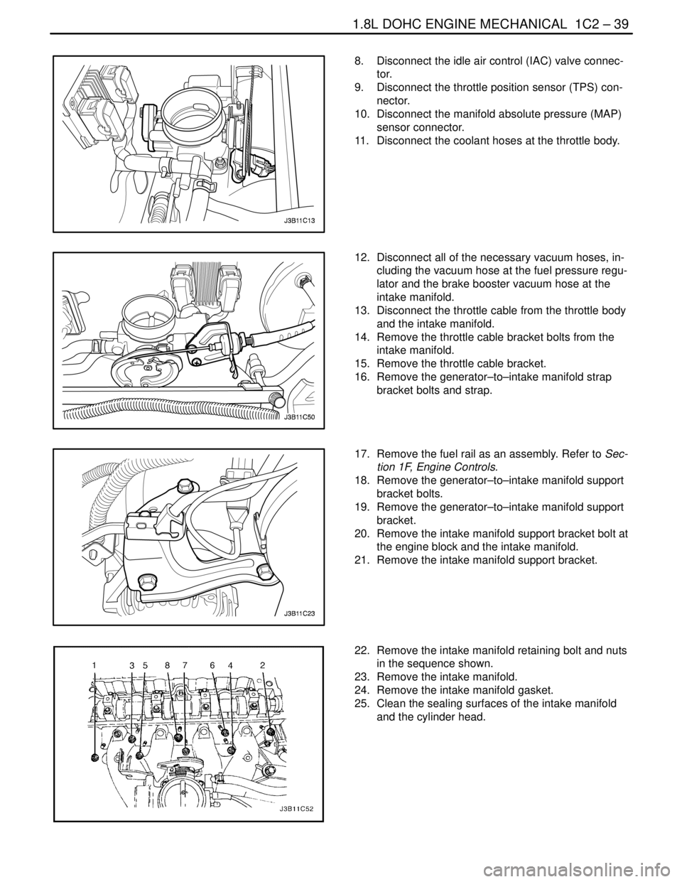
8. Disconnect the idle air control (IAC) valve connec-
tor.
9. Disconnect the throttle position sensor (TPS) con-
nector.
10. Disconnect the manifold absolute pressure (MAP)
sensor connector.
11. Disconnect the coolant hoses at the throttle body.
12. Disconnect all of the necessary vacuum hoses, in-
cluding the vacuum hose at the fuel pressure regu-
lator and the brake booster vacuum hose at the
intake manifold.
13. Disconnect the throttle cable from the throttle body
and the intake manifold.
14. Remove the throttle cable bracket bolts from the
intake manifold.
15. Remove the throttle cable bracket.
16. Remove the generator–to–intake manifold strap
bracket bolts and strap.
17. Remove the fuel rail as an assembly. Refer to Sec-
tion 1F, Engine Controls.
18. Remove the generator–to–intake manifold support
bracket bolts.
19. Remove the generator–to–intake manifold support
bracket.
20. Remove the intake manifold support bracket bolt at
the engine block and the intake manifold.
21. Remove the intake manifold support bracket.
22. Remove the intake manifold retaining bolt and nuts
in the sequence shown.
23. Remove the intake manifold.
24. Remove the intake manifold gasket.
25. Clean the sealing surfaces of the intake manifold
and the cylinder head.
Page 160 of 2643
1C2 – 40I1.8L DOHC ENGINE MECHANICAL
DAEWOO V–121 BL4
Installation Procedure
1. Install the intake manifold gasket.
2. Install the intake manifold.
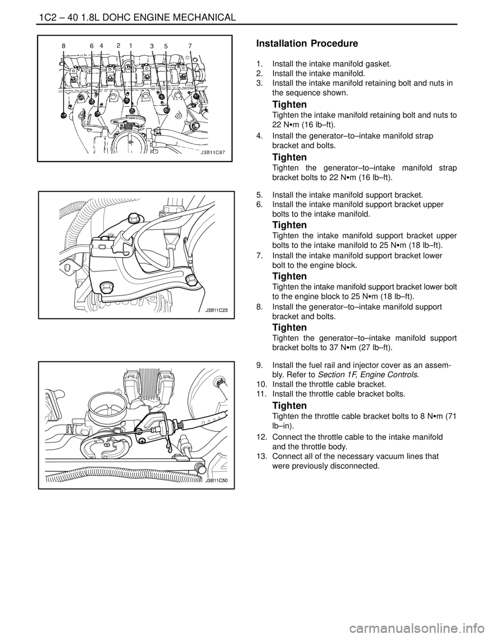
3. Install the intake manifold retaining bolt and nuts in
the sequence shown.
Tighten
Tighten the intake manifold retaining bolt and nuts to
22 NSm (16 lb–ft).
4. Install the generator–to–intake manifold strap
bracket and bolts.
Tighten
Tighten the generator–to–intake manifold strap
bracket bolts to 22 NSm (16 lb–ft).
5. Install the intake manifold support bracket.
6. Install the intake manifold support bracket upper
bolts to the intake manifold.
Tighten
Tighten the intake manifold support bracket upper
bolts to the intake manifold to 25 NSm (18 lb–ft).
7. Install the intake manifold support bracket lower
bolt to the engine block.
Tighten
Tighten the intake manifold support bracket lower bolt
to the engine block to 25 NSm (18 lb–ft).
8. Install the generator–to–intake manifold support
bracket and bolts.
Tighten
Tighten the generator–to–intake manifold support
bracket bolts to 37 NSm (27 lb–ft).
9. Install the fuel rail and injector cover as an assem-
bly. Refer to Section 1F, Engine Controls.
10. Install the throttle cable bracket.
11. Install the throttle cable bracket bolts.
Tighten
Tighten the throttle cable bracket bolts to 8 NSm (71
lb–in).
12. Connect the throttle cable to the intake manifold
and the throttle body.
13. Connect all of the necessary vacuum lines that
were previously disconnected.
Page 161 of 2643
1.8L DOHC ENGINE MECHANICAL 1C2 – 41
DAEWOO V–121 BL4
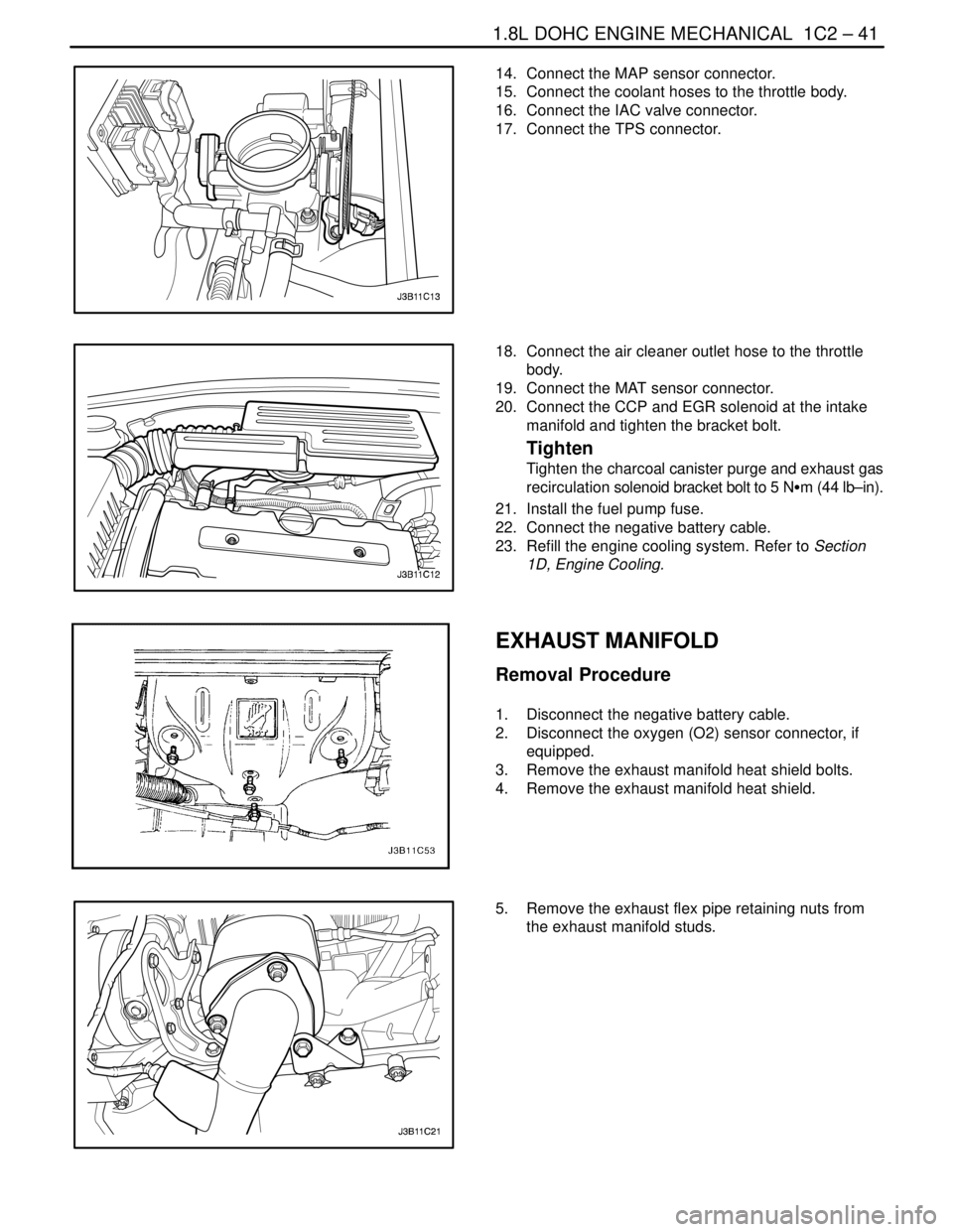
14. Connect the MAP sensor connector.
15. Connect the coolant hoses to the throttle body.
16. Connect the IAC valve connector.
17. Connect the TPS connector.
18. Connect the air cleaner outlet hose to the throttle
body.
19. Connect the MAT sensor connector.
20. Connect the CCP and EGR solenoid at the intake
manifold and tighten the bracket bolt.
Tighten
Tighten the charcoal canister purge and exhaust gas
recirculation solenoid bracket bolt to 5 NSm (44 lb–in).
21. Install the fuel pump fuse.
22. Connect the negative battery cable.
23. Refill the engine cooling system. Refer to Section
1D, Engine Cooling.
EXHAUST MANIFOLD
Removal Procedure
1. Disconnect the negative battery cable.
2. Disconnect the oxygen (O2) sensor connector, if
equipped.
3. Remove the exhaust manifold heat shield bolts.
4. Remove the exhaust manifold heat shield.
5. Remove the exhaust flex pipe retaining nuts from
the exhaust manifold studs.
Page 167 of 2643
1.8L DOHC ENGINE MECHANICAL 1C2 – 47
DAEWOO V–121 BL4
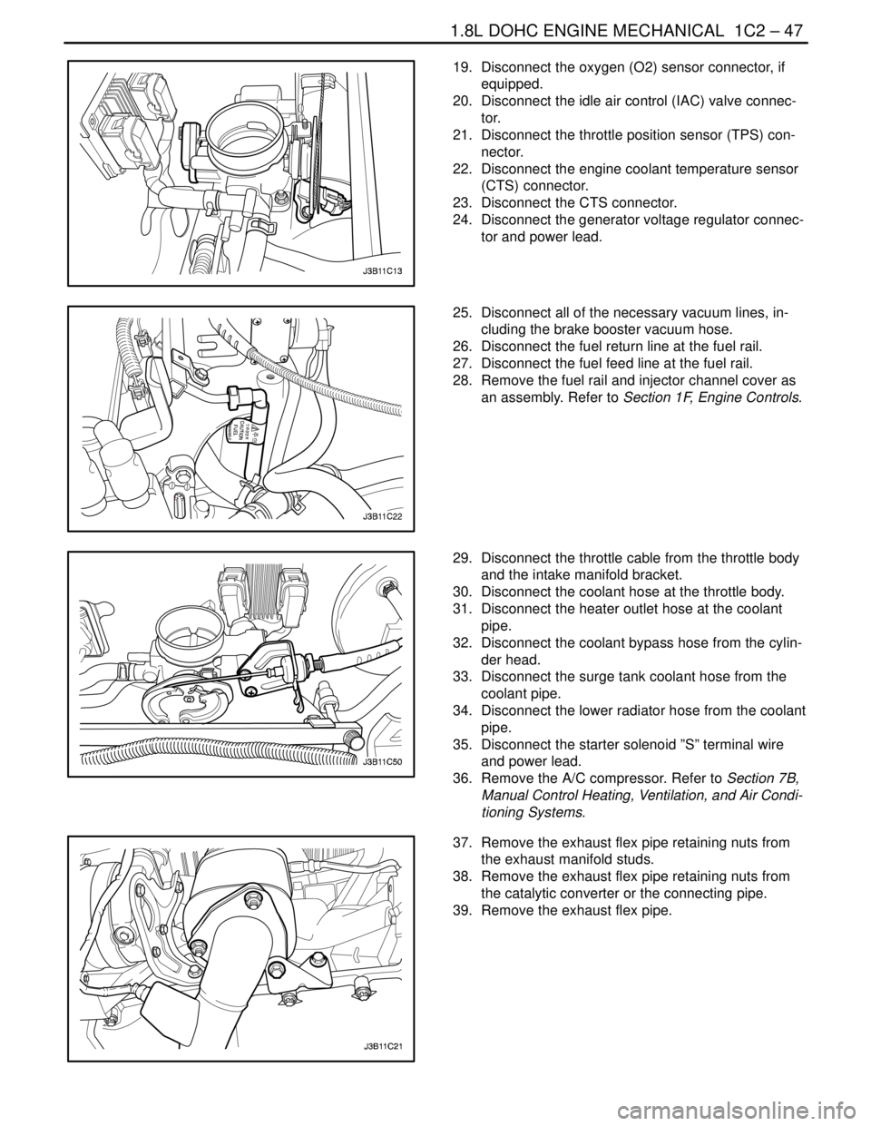
19. Disconnect the oxygen (O2) sensor connector, if
equipped.
20. Disconnect the idle air control (IAC) valve connec-
tor.
21. Disconnect the throttle position sensor (TPS) con-
nector.
22. Disconnect the engine coolant temperature sensor
(CTS) connector.
23. Disconnect the CTS connector.
24. Disconnect the generator voltage regulator connec-
tor and power lead.
25. Disconnect all of the necessary vacuum lines, in-
cluding the brake booster vacuum hose.
26. Disconnect the fuel return line at the fuel rail.
27. Disconnect the fuel feed line at the fuel rail.
28. Remove the fuel rail and injector channel cover as
an assembly. Refer to Section 1F, Engine Controls.
29. Disconnect the throttle cable from the throttle body
and the intake manifold bracket.
30. Disconnect the coolant hose at the throttle body.
31. Disconnect the heater outlet hose at the coolant
pipe.
32. Disconnect the coolant bypass hose from the cylin-
der head.
33. Disconnect the surge tank coolant hose from the
coolant pipe.
34. Disconnect the lower radiator hose from the coolant
pipe.
35. Disconnect the starter solenoid ”S” terminal wire
and power lead.
36. Remove the A/C compressor. Refer to Section 7B,
Manual Control Heating, Ventilation, and Air Condi-
tioning Systems.
37. Remove the exhaust flex pipe retaining nuts from
the exhaust manifold studs.
38. Remove the exhaust flex pipe retaining nuts from
the catalytic converter or the connecting pipe.
39. Remove the exhaust flex pipe.
Page 171 of 2643
1.8L DOHC ENGINE MECHANICAL 1C2 – 51
DAEWOO V–121 BL4
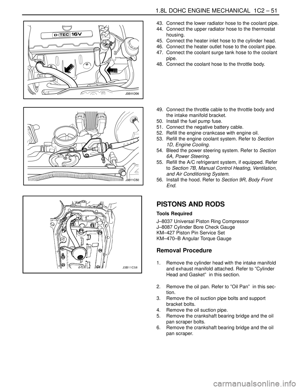
43. Connect the lower radiator hose to the coolant pipe.
44. Connect the upper radiator hose to the thermostat
housing.
45. Connect the heater inlet hose to the cylinder head.
46. Connect the heater outlet hose to the coolant pipe.
47. Connect the coolant surge tank hose to the coolant
pipe.
48. Connect the coolant hose to the throttle body.
49. Connect the throttle cable to the throttle body and
the intake manifold bracket.
50. Install the fuel pump fuse.
51. Connect the negative battery cable.
52. Refill the engine crankcase with engine oil.
53. Refill the engine coolant system. Refer to Section
1D, Engine Cooling.
54. Bleed the power steering system. Refer to Section
6A, Power Steering.
55. Refill the A/C refrigerant system, if equipped. Refer
to Section 7B, Manual Control Heating, Ventilation,
and Air Conditioning System.
56. Install the hood. Refer to Section 9R, Body Front
End.
PISTONS AND RODS
Tools Required
J–8037 Universal Piston Ring Compressor
J–8087 Cylinder Bore Check Gauge
KM–427 Piston Pin Service Set
KM–470–B Angular Torque Gauge
Removal Procedure
1. Remove the cylinder head with the intake manifold
and exhaust manifold attached. Refer to ”Cylinder
Head and Gasket” in this section.
2. Remove the oil pan. Refer to ”Oil Pan” in this sec-
tion.
3. Remove the oil suction pipe bolts and support
bracket bolts.
4. Remove the oil suction pipe.
5. Remove the crankshaft bearing bridge and the oil
pan scraper bolts.
6. Remove the crankshaft bearing bridge and the oil
pan scraper.
Page 175 of 2643
1.8L DOHC ENGINE MECHANICAL 1C2 – 55
DAEWOO V–121 BL4
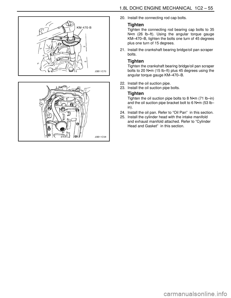
20. Install the connecting rod cap bolts.
Tighten
Tighten the connecting rod bearing cap bolts to 35
NSm (26 lb–ft). Using the angular torque gauge
KM–470–B, tighten the bolts one turn of 45 degrees
plus one turn of 15 degrees.
21. Install the crankshaft bearing bridge/oil pan scraper
bolts.
Tighten
Tighten the crankshaft bearing bridge/oil pan scraper
bolts to 20 NSm (15 lb–ft) plus 45 degrees using the
angular torque gauge KM–470–B.
22. Install the oil suction pipe.
23. Install the oil suction pipe bolts.
Tighten
Tighten the oil suction pipe bolts to 8 NSm (71 lb–in)
and the oil suction pipe bracket bolt to 6 NSm (53 lb–
in).
24. Install the oil pan. Refer to ”Oil Pan” in this section.
25. Install the cylinder head with the intake manifold
and exhaust manifold attached. Refer to ”Cylinder
Head and Gasket” in this section.
Page 176 of 2643
1C2 – 56I1.8L DOHC ENGINE MECHANICAL
DAEWOO V–121 BL4
UNIT REPAIR
CYLINDER HEAD AND VALVE TRAIN
COMPONENTS
Tools Required
MKM–571–B Gauge
KM–340–0 Cutter Set
KM–340–7 Guide Drift
KM–340–13 Cutters
KM–340–26 Cutters
KM–348 Valve Spring Compressor
KM–653 Adapter
KM–805 Valve Guide Reamer
Disassembly Procedure
1. Remove the cylinder head with the intake manifold
and the exhaust manifold attached. Refer to ”Cylin-
der Head and Gasket” in this section.
2. Remove the exhaust manifold heat shield bolts.
3. Remove the exhaust manifold heat shield.
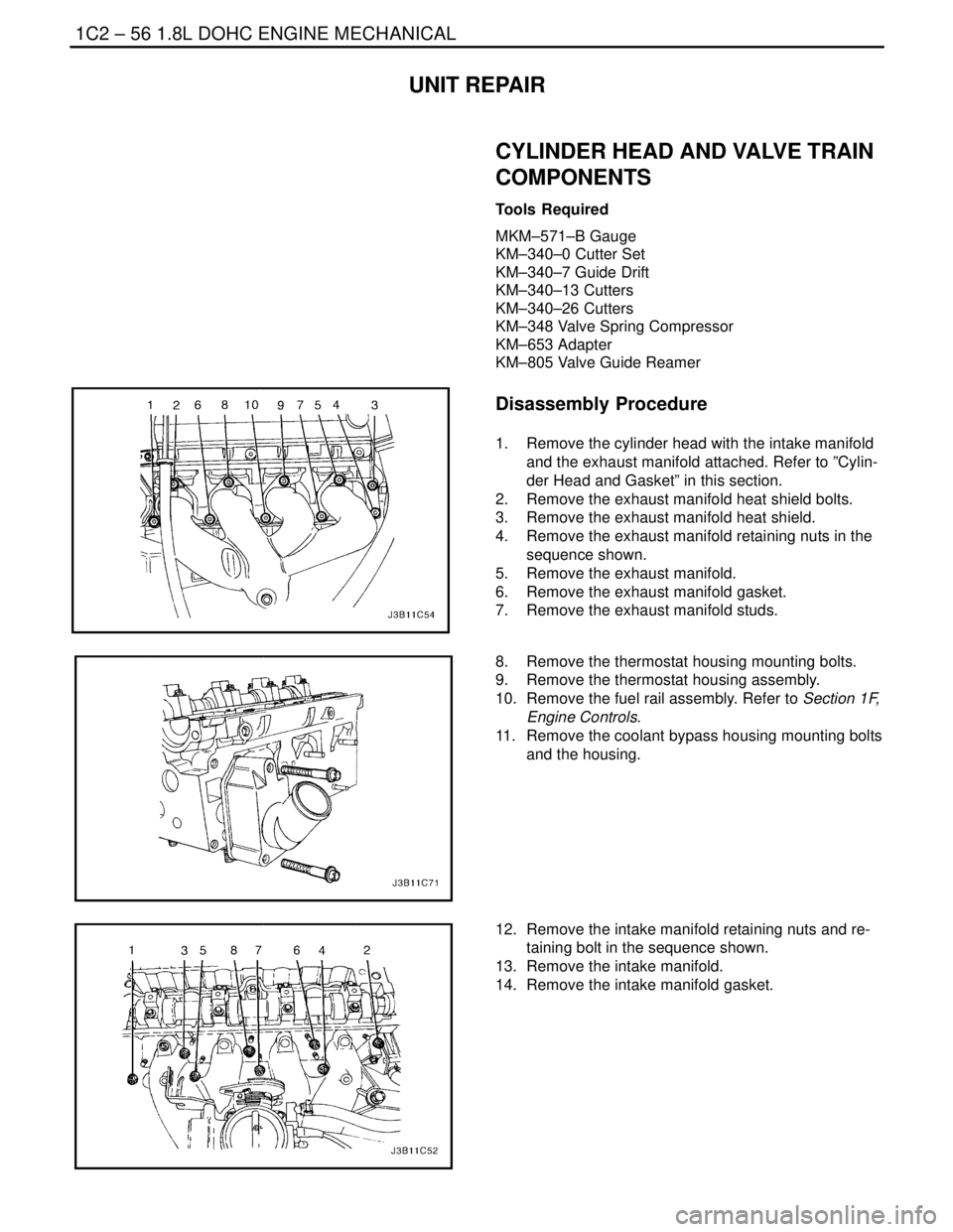
4. Remove the exhaust manifold retaining nuts in the
sequence shown.
5. Remove the exhaust manifold.
6. Remove the exhaust manifold gasket.
7. Remove the exhaust manifold studs.
8. Remove the thermostat housing mounting bolts.
9. Remove the thermostat housing assembly.
10. Remove the fuel rail assembly. Refer to Section 1F,
Engine Controls.
11. Remove the coolant bypass housing mounting bolts
and the housing.
12. Remove the intake manifold retaining nuts and re-
taining bolt in the sequence shown.
13. Remove the intake manifold.
14. Remove the intake manifold gasket.
Page 177 of 2643
1.8L DOHC ENGINE MECHANICAL 1C2 – 57
DAEWOO V–121 BL4
15. Remove the direct ignition system (DIS) coil and
the exhaust gas recirculation (EGR) mounting
bracket bolts.
16. Remove the DIS ignition coil and the EGR mount-
ing bracket and ignition wires.
17. Remove the intake manifold studs.
18. Remove the spark plugs.
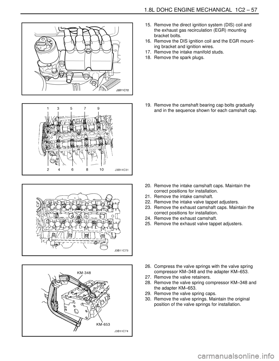
19. Remove the camshaft bearing cap bolts gradually
and in the sequence shown for each camshaft cap.
20. Remove the intake camshaft caps. Maintain the
correct positions for installation.
21. Remove the intake camshaft.
22. Remove the intake valve tappet adjusters.
23. Remove the exhaust camshaft caps. Maintain the
correct positions for installation.
24. Remove the exhaust camshaft.
25. Remove the exhaust valve tappet adjusters.
26. Compress the valve springs with the valve spring
compressor KM–348 and the adapter KM–653.
27. Remove the valve retainers.
28. Remove the valve spring compressor KM–348 and
the adapter KM–653.
29. Remove the valve spring caps.
30. Remove the valve springs. Maintain the original
position of the valve springs for installation.
Page 182 of 2643
1C2 – 62I1.8L DOHC ENGINE MECHANICAL
DAEWOO V–121 BL4
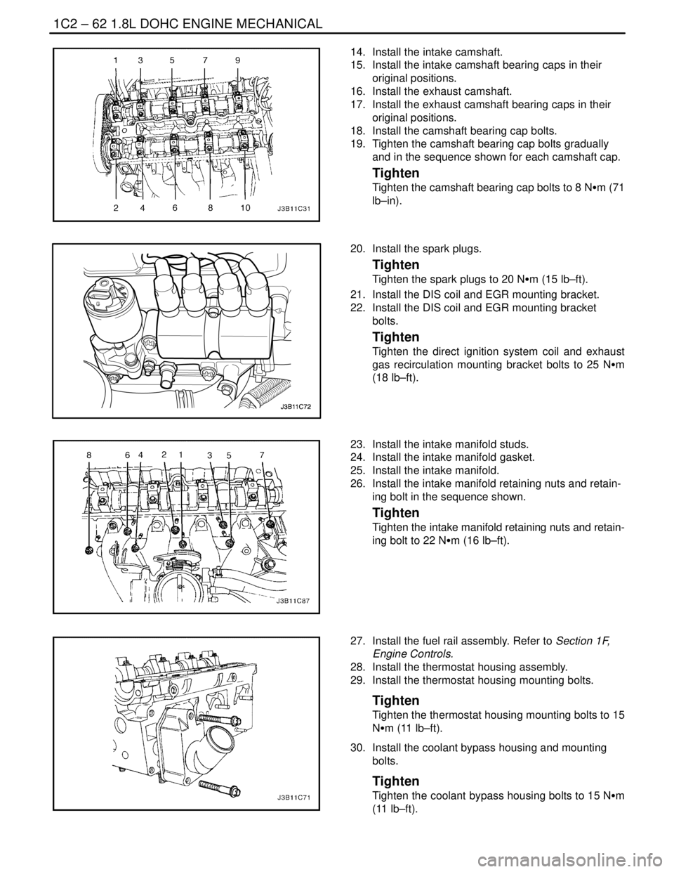
14. Install the intake camshaft.
15. Install the intake camshaft bearing caps in their
original positions.
16. Install the exhaust camshaft.
17. Install the exhaust camshaft bearing caps in their
original positions.
18. Install the camshaft bearing cap bolts.
19. Tighten the camshaft bearing cap bolts gradually
and in the sequence shown for each camshaft cap.
Tighten
Tighten the camshaft bearing cap bolts to 8 NSm (71
lb–in).
20. Install the spark plugs.
Tighten
Tighten the spark plugs to 20 NSm (15 lb–ft).
21. Install the DIS coil and EGR mounting bracket.
22. Install the DIS coil and EGR mounting bracket
bolts.
Tighten
Tighten the direct ignition system coil and exhaust
gas recirculation mounting bracket bolts to 25 NSm
(18 lb–ft).
23. Install the intake manifold studs.
24. Install the intake manifold gasket.
25. Install the intake manifold.
26. Install the intake manifold retaining nuts and retain-
ing bolt in the sequence shown.
Tighten
Tighten the intake manifold retaining nuts and retain-
ing bolt to 22 NSm (16 lb–ft).
27. Install the fuel rail assembly. Refer to Section 1F,
Engine Controls.
28. Install the thermostat housing assembly.
29. Install the thermostat housing mounting bolts.
Tighten
Tighten the thermostat housing mounting bolts to 15
NSm (11 lb–ft).
30. Install the coolant bypass housing and mounting
bolts.
Tighten
Tighten the coolant bypass housing bolts to 15 NSm
(11 lb–ft).
Page 183 of 2643
1.8L DOHC ENGINE MECHANICAL 1C2 – 63
DAEWOO V–121 BL4
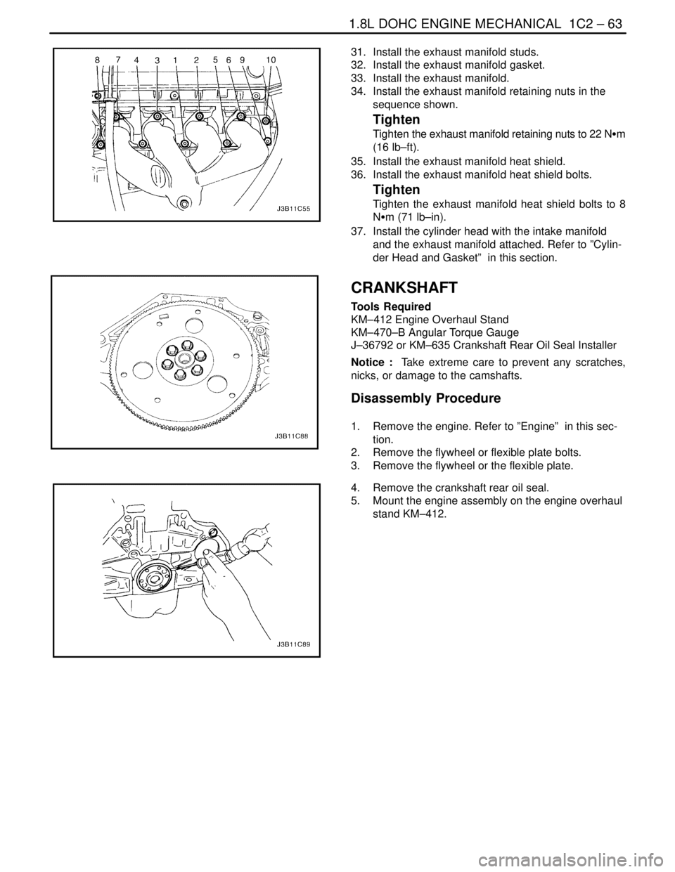
31. Install the exhaust manifold studs.
32. Install the exhaust manifold gasket.
33. Install the exhaust manifold.
34. Install the exhaust manifold retaining nuts in the
sequence shown.
Tighten
Tighten the exhaust manifold retaining nuts to 22 NSm
(16 lb–ft).
35. Install the exhaust manifold heat shield.
36. Install the exhaust manifold heat shield bolts.
Tighten
Tighten the exhaust manifold heat shield bolts to 8
NSm (71 lb–in).
37. Install the cylinder head with the intake manifold
and the exhaust manifold attached. Refer to ”Cylin-
der Head and Gasket” in this section.
CRANKSHAFT
Tools Required
KM–412 Engine Overhaul Stand
KM–470–B Angular Torque Gauge
J–36792 or KM–635 Crankshaft Rear Oil Seal Installer
Notice : Take extreme care to prevent any scratches,
nicks, or damage to the camshafts.
Disassembly Procedure
1. Remove the engine. Refer to ”Engine” in this sec-
tion.
2. Remove the flywheel or flexible plate bolts.
3. Remove the flywheel or the flexible plate.
4. Remove the crankshaft rear oil seal.
5. Mount the engine assembly on the engine overhaul
stand KM–412.