fuel pressure DAEWOO NUBIRA 2004 Service Workshop Manual
[x] Cancel search | Manufacturer: DAEWOO, Model Year: 2004, Model line: NUBIRA, Model: DAEWOO NUBIRA 2004Pages: 2643, PDF Size: 80.54 MB
Page 410 of 2643

1F – 164IENGINE CONTROLS
DAEWOO V–121 BL4
StepNo Yes Value(s) Action
131. Disconnect the vacuum hose from the fuel
pressure regulator and inspect the hose for the
presence of fuel.
2. If fuel is presence in the vacuum hose, replace
the fuel pressure regulator.
Is the repair complete?–Go to Step 21Go to Step 14
141. Turn the ignition ON.
2. Slowly press the acceleration pedal.
Does the Throttle Position (TP) sensor display in-
crease steady and evenly from its minimum voltage
at closed throttle to its maximum voltage at Wide–
Open Throttle (WOT).–Go to Step 15Go to Step 19
151. Perform the Fuel System Diagnosis.
2. If the table isolate a problem, repair as needed.
Is the repair complete?–Go to Step 21Go to Step 16
161. Perform the Evaporative Emission (EVAP)
Control System Diagnosis.
2. If the table isolate a problem, repair as needed.
Is the repair complete?–Go to Step 21Go to Step 17
171. Perform the Fuel Injector Balance Test.
2. If the table isolate a problem, repair as needed.
Is the repair complete?–Go to Step 21Go to Step 18
181. Remove the Oxygen Sensor (O2S).
2. Visually/physically inspect the O2S for silicone
contamination.
3. Note: this will be indicated by a powdery white
deposit on the portion of the O2S exposed to
the exhaust stream.
4. If contamination is present on the O2S, find the
source and repair as needed.
Is the repair complete?–Go to Step 21Go to
”Diagnostic
Aids”
191. Check the TP sensor mounting screws.
2. If they are too loose or missing tighten or re-
place them as needed.
3. If the screws are OK, replace the TP sensor.
Is the repair complete?–Go to Step 21–
201. Turn the ignition OFF.
2. Replace the MAP sensor.
Is the repair complete?–Go to Step 21–
211. Using the scan tool, clear the Diagnostic
Trouble Codes (DTCs).
2. Start the engine and idle at normal operating
temperature.
3. Operate the vehicle within the Conditions for
setting this DTC as specified in the supporting
text.
Does the scan tool indicate that this diagnostic has
run and passed?–Go to Step 21Go to Step 2
22Check if any additional DTCs are set.
Are any DTCs displayed that have not been diag-
nosed?–Go to
applicable DTC
tableSystem OK
Page 435 of 2643

ENGINE CONTROLS 1F – 189
DAEWOO V–121 BL4
StepNo Yes Value(s) Action
71. Turn the engine OFF.
2. Install a fuel pressure gauge to the fuel rail.
3. Observe the fuel pressure with the engine run-
ning.
Is the fuel pressure within the specified value?284–325 kPa
(41–47 psi)Go to Step 8Go to
”Fuel System
Diagnosis”
8Check the fuel for contamination.
Is the fuel OK?–Go to Step 9Go to Step 10
9Check for a basic engine problem and repair as nec-
essary.
Is the repair complete?–Go to Step 27–
10Replace the contaminated fuel.
Is the repair complete?–Go to Step 27–
111. Turn the engine OFF.
2. Disconnect the fuel injector harness connector.
3. Install a spark tester on cylinder #1 spark plug
cable.
4. Crank the engine and check for spark.
5. Repeat the above procedure on cylinders #2,
#3 and #4.
Is a spark observed on all four spark plug cables?–Go to Step 12Go to Step 20
12Replace any malfunctioning spark plugs if neces-
sary.
Is the repair complete?–Go to Step 27Go to Step 13
131. Turn the engine OFF.
2. Disconnect the fuel injector connectors from
the injectors.
3. Install an injector test light on the injector har-
ness connector for the cylinders that had mis-
fired.
4. Crank the engine and note the test light.
Does the injector test light blink?–Go to Step 14Go to Step 15
14Perform the Fuel Injector Balance Test.
Are the fuel injectors OK?–Go to Step 9Go to Step 16
151. Disconnect the injector test light.
2. With a test light connected to ground, probe
the ignition feed terminal 2 of the injector har-
ness connector for each cylinder that had mis-
fire.
3. Crank the engine.
Does the test light illuminate?–Go to Step 17Go to Step 19
16Replace any malfunctioning fuel injectors.
Is the repair complete?Go to Step 27–
17Check the affected fuel injector driver circuit at termi-
nals 59, 89, 90, and 60 for an open, short, or short
to voltage.
Is a problem found?–Go to Step 18Go to Step 24
18Repair the open or the shorted fuel injector driver cir-
cuit.
Is the repair complete?–Go to Step 27–
Page 439 of 2643

ENGINE CONTROLS 1F – 193
DAEWOO V–121 BL4
StepNo Yes Value(s) Action
71. Turn the engine OFF.
2. Install a fuel pressure gauge to the fuel rail.
3. Observe the fuel pressure with the engine run-
ning.
Is the fuel pressure within the specified value?284–325 kPa
(41–47 psi)Go to Step 8Go to
”Fuel System
Diagnosis”
8Check the fuel for contamination.
Is the fuel OK?–Go to Step 9Go to Step 10
9Check for a basic engine problem and repair as nec-
essary.
Is the repair complete?–Go to Step 27–
10Replace the contaminated fuel.
Is the repair complete?–Go to Step 27–
111. Turn the engine OFF.
2. Disconnect the fuel injector harness connector.
3. Install a spark tester on cylinder #1 spark plug
cable.
4. Crank the engine and check for spark.
5. Repeat the above procedure on cylinders #2,
#3 and #4.
Is a spark observed on all four spark plug cables?–Go to Step 12Go to Step 20
12Replace any malfunctioning spark plugs if neces-
sary.
Is the repair complete?–Go to Step 27Go to Step 13
131. Turn the engine OFF.
2. Disconnect the fuel injector connectors from
the injectors.
3. Install an injector test light on the injector har-
ness connector for the cylinders that had mis-
fired.
4. Crank the engine and note the test light.
Does the injector test light blink?–Go to Step 14Go to Step 15
14Perform the Fuel Injector Balance Test.
Are the fuel injectors OK?–Go to Step 9Go to Step 16
151. Disconnect the injector test light.
2. With a test light connected to ground, probe
the ignition feed terminal 2 of the injector har-
ness connector for each cylinder that had mis-
fire.
3. Crank the engine.
Does the test light illuminate?–Go to Step 17Go to Step 19
16Replace any malfunctioning fuel injectors.
Is the repair complete?Go to Step 27–
17Check the affected fuel injector driver circuit at termi-
nals 59, 89, 90, and 60 for an open, short, or short
to voltage.
Is a problem found?–Go to Step 18Go to Step 24
18Repair the open or the shorted fuel injector driver cir-
cuit.
Is the repair complete?–Go to Step 27–
Page 464 of 2643
1F – 218IENGINE CONTROLS
DAEWOO V–121 BL4
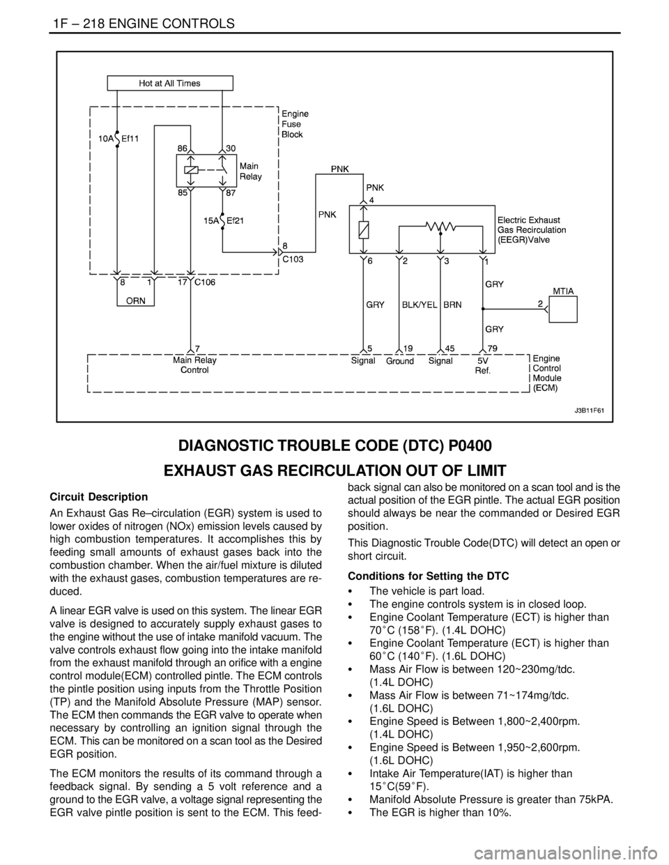
DIAGNOSTIC TROUBLE CODE (DTC) P0400
EXHAUST GAS RECIRCULATION OUT OF LIMIT
Circuit Description
An Exhaust Gas Re–circulation (EGR) system is used to
lower oxides of nitrogen (NOx) emission levels caused by
high combustion temperatures. It accomplishes this by
feeding small amounts of exhaust gases back into the
combustion chamber. When the air/fuel mixture is diluted
with the exhaust gases, combustion temperatures are re-
duced.
A linear EGR valve is used on this system. The linear EGR
valve is designed to accurately supply exhaust gases to
the engine without the use of intake manifold vacuum. The
valve controls exhaust flow going into the intake manifold
from the exhaust manifold through an orifice with a engine
control module(ECM) controlled pintle. The ECM controls
the pintle position using inputs from the Throttle Position
(TP) and the Manifold Absolute Pressure (MAP) sensor.
The ECM then commands the EGR valve to operate when
necessary by controlling an ignition signal through the
ECM. This can be monitored on a scan tool as the Desired
EGR position.
The ECM monitors the results of its command through a
feedback signal. By sending a 5 volt reference and a
ground to the EGR valve, a voltage signal representing the
EGR valve pintle position is sent to the ECM. This feed-back signal can also be monitored on a scan tool and is the
actual position of the EGR pintle. The actual EGR position
should always be near the commanded or Desired EGR
position.
This Diagnostic Trouble Code(DTC) will detect an open or
short circuit.
Conditions for Setting the DTC
S The vehicle is part load.
S The engine controls system is in closed loop.
S Engine Coolant Temperature (ECT) is higher than
70°C (158°F). (1.4L DOHC)
S Engine Coolant Temperature (ECT) is higher than
60°C (140°F). (1.6L DOHC)
S Mass Air Flow is between 120~230mg/tdc.
(1.4L DOHC)
S Mass Air Flow is between 71~174mg/tdc.
(1.6L DOHC)
S Engine Speed is Between 1,800~2,400rpm.
(1.4L DOHC)
S Engine Speed is Between 1,950~2,600rpm.
(1.6L DOHC)
S Intake Air Temperature(IAT) is higher than
15°C(59°F).
S Manifold Absolute Pressure is greater than 75kPA.
S The EGR is higher than 10%.
Page 467 of 2643
ENGINE CONTROLS 1F – 221
DAEWOO V–121 BL4
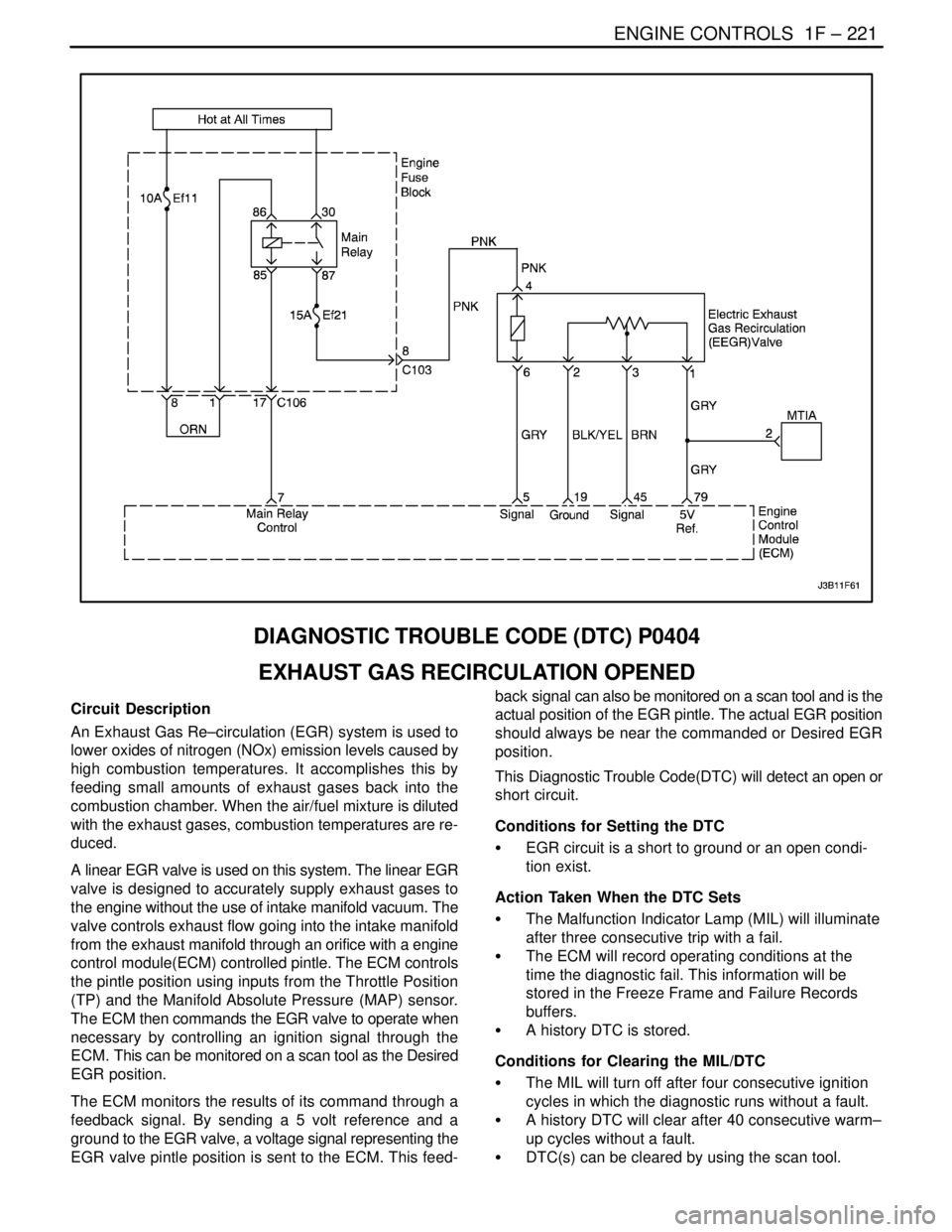
DIAGNOSTIC TROUBLE CODE (DTC) P0404
EXHAUST GAS RECIRCULATION OPENED
Circuit Description
An Exhaust Gas Re–circulation (EGR) system is used to
lower oxides of nitrogen (NOx) emission levels caused by
high combustion temperatures. It accomplishes this by
feeding small amounts of exhaust gases back into the
combustion chamber. When the air/fuel mixture is diluted
with the exhaust gases, combustion temperatures are re-
duced.
A linear EGR valve is used on this system. The linear EGR
valve is designed to accurately supply exhaust gases to
the engine without the use of intake manifold vacuum. The
valve controls exhaust flow going into the intake manifold
from the exhaust manifold through an orifice with a engine
control module(ECM) controlled pintle. The ECM controls
the pintle position using inputs from the Throttle Position
(TP) and the Manifold Absolute Pressure (MAP) sensor.
The ECM then commands the EGR valve to operate when
necessary by controlling an ignition signal through the
ECM. This can be monitored on a scan tool as the Desired
EGR position.
The ECM monitors the results of its command through a
feedback signal. By sending a 5 volt reference and a
ground to the EGR valve, a voltage signal representing the
EGR valve pintle position is sent to the ECM. This feed-back signal can also be monitored on a scan tool and is the
actual position of the EGR pintle. The actual EGR position
should always be near the commanded or Desired EGR
position.
This Diagnostic Trouble Code(DTC) will detect an open or
short circuit.
Conditions for Setting the DTC
S EGR circuit is a short to ground or an open condi-
tion exist.
Action Taken When the DTC Sets
S The Malfunction Indicator Lamp (MIL) will illuminate
after three consecutive trip with a fail.
S The ECM will record operating conditions at the
time the diagnostic fail. This information will be
stored in the Freeze Frame and Failure Records
buffers.
S A history DTC is stored.
Conditions for Clearing the MIL/DTC
S The MIL will turn off after four consecutive ignition
cycles in which the diagnostic runs without a fault.
S A history DTC will clear after 40 consecutive warm–
up cycles without a fault.
S DTC(s) can be cleared by using the scan tool.
Page 470 of 2643
1F – 224IENGINE CONTROLS
DAEWOO V–121 BL4
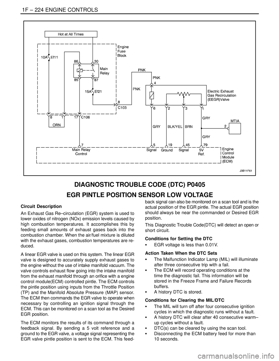
DIAGNOSTIC TROUBLE CODE (DTC) P0405
EGR PINTLE POSITION SENSOR LOW VOLTAGE
Circuit Description
An Exhaust Gas Re–circulation (EGR) system is used to
lower oxides of nitrogen (NOx) emission levels caused by
high combustion temperatures. It accomplishes this by
feeding small amounts of exhaust gases back into the
combustion chamber. When the air/fuel mixture is diluted
with the exhaust gases, combustion temperatures are re-
duced.
A linear EGR valve is used on this system. The linear EGR
valve is designed to accurately supply exhaust gases to
the engine without the use of intake manifold vacuum. The
valve controls exhaust flow going into the intake manifold
from the exhaust manifold through an orifice with a engine
control module(ECM) controlled pintle. The ECM controls
the pintle position using inputs from the Throttle Position
(TP) and the Manifold Absolute Pressure (MAP) sensor.
The ECM then commands the EGR valve to operate when
necessary by controlling an ignition signal through the
ECM. This can be monitored on a scan tool as the Desired
EGR position.
The ECM monitors the results of its command through a
feedback signal. By sending a 5 volt reference and a
ground to the EGR valve, a voltage signal representing the
EGR valve pintle position is sent to the ECM. This feed-back signal can also be monitored on a scan tool and is the
actual position of the EGR pintle. The actual EGR position
should always be near the commanded or Desired EGR
position.
This Diagnostic Trouble Code(DTC) will detect an open or
short circuit.
Conditions for Setting the DTC
S EGR voltage is less than 0.01V.
Action Taken When the DTC Sets
S The Malfunction Indicator Lamp (MIL) will illuminate
after three consecutive trip with a fail.
S The ECM will record operating conditions at the
time the diagnostic fail. This information will be
stored in the Freeze Frame and Failure Records
buffers.
S A history DTC is stored.
Conditions for Clearing the MIL/DTC
S The MIL will turn off after four consecutive ignition
cycles in which the diagnostic runs without a fault.
S A history DTC will clear after 40 consecutive warm–
up cycles without a fault.
S DTC(s) can be cleared by using the scan tool.
S Disconnecting the ECM battery feed for more than
10 seconds.
Page 473 of 2643
ENGINE CONTROLS 1F – 227
DAEWOO V–121 BL4
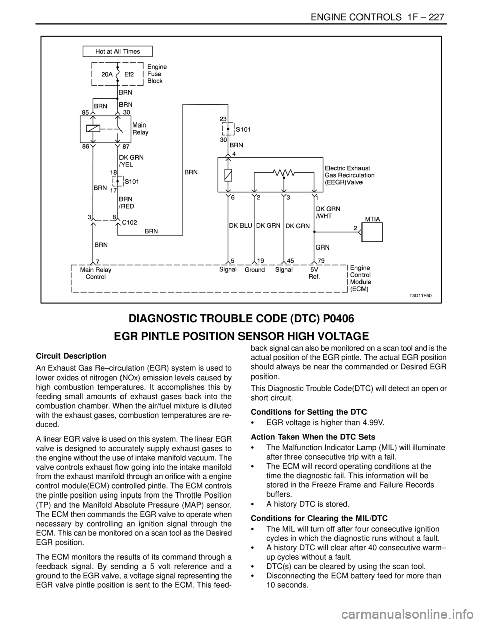
DIAGNOSTIC TROUBLE CODE (DTC) P0406
EGR PINTLE POSITION SENSOR HIGH VOLTAGE
Circuit Description
An Exhaust Gas Re–circulation (EGR) system is used to
lower oxides of nitrogen (NOx) emission levels caused by
high combustion temperatures. It accomplishes this by
feeding small amounts of exhaust gases back into the
combustion chamber. When the air/fuel mixture is diluted
with the exhaust gases, combustion temperatures are re-
duced.
A linear EGR valve is used on this system. The linear EGR
valve is designed to accurately supply exhaust gases to
the engine without the use of intake manifold vacuum. The
valve controls exhaust flow going into the intake manifold
from the exhaust manifold through an orifice with a engine
control module(ECM) controlled pintle. The ECM controls
the pintle position using inputs from the Throttle Position
(TP) and the Manifold Absolute Pressure (MAP) sensor.
The ECM then commands the EGR valve to operate when
necessary by controlling an ignition signal through the
ECM. This can be monitored on a scan tool as the Desired
EGR position.
The ECM monitors the results of its command through a
feedback signal. By sending a 5 volt reference and a
ground to the EGR valve, a voltage signal representing the
EGR valve pintle position is sent to the ECM. This feed-back signal can also be monitored on a scan tool and is the
actual position of the EGR pintle. The actual EGR position
should always be near the commanded or Desired EGR
position.
This Diagnostic Trouble Code(DTC) will detect an open or
short circuit.
Conditions for Setting the DTC
S EGR voltage is higher than 4.99V.
Action Taken When the DTC Sets
S The Malfunction Indicator Lamp (MIL) will illuminate
after three consecutive trip with a fail.
S The ECM will record operating conditions at the
time the diagnostic fail. This information will be
stored in the Freeze Frame and Failure Records
buffers.
S A history DTC is stored.
Conditions for Clearing the MIL/DTC
S The MIL will turn off after four consecutive ignition
cycles in which the diagnostic runs without a fault.
S A history DTC will clear after 40 consecutive warm–
up cycles without a fault.
S DTC(s) can be cleared by using the scan tool.
S Disconnecting the ECM battery feed for more than
10 seconds.
Page 476 of 2643
1F – 230IENGINE CONTROLS
DAEWOO V–121 BL4
DIAGNOSTIC TROUBLE CODE (DTC) P0420
CATALYST LOW EFFICIENCY
Circuit Description
In order to control exhaust emissions of Hydrocarbons
(HC), Carbon Monoxide (CO) and Nitrogen Oxide (NOx),
a Three–Way Catalytic Converter (TWC) is used. The cat-
alyst within the converter promotes a chemical reaction
which oxidizes the HC and CO present in the exhaust gas,
converting them into harmless water vapor and carbon
dioxide, it also reduces NOx, converting it into nitrogen.
The catalytic converter also has the ability to store oxygen.
The Engine Control Module (ECM) has the capability to
monitor this process using a Heated Oxygen Sensor
(HO2S) located in the exhaust stream past the TWC. The
HO2S produces an output signal which indicates the oxy-
gen storage capacity of the catalyst; this in turn indicates
the catalyst’s ability to convert exhaust emissions effec-
tively. The ECM monitors the catalyst efficiency by first al-
lowing the catalyst to heat up, waiting for a stabilization pe-
riod while the engine is idling, and then adding and
removing fuel while monitoring the reaction of the HO2S.
When the catalyst is functioning properly, the HO2S re-
sponse to the extra fuel is slow compared to the Oxygen
Sensor (O2S). When the HO2S response is close to that
of the O2S, the Oxygen storage capability or efficiency of
the catalyst is considered to be bad, and the Malfunction
Indicator Lamp (MIL) will illuminate.
Conditions for Setting the DTC
S Closed loop stoichiometry.
S Engine Coolant Temperature (ECT) is more than
75°C (167°F) . (1.4L DOHC)
S Engine Coolant Temperature (ECT) is more than
70°C (158°F) . (1.6L DOHC)
S Engine speed between 1,766rpm and 2,368rpm.
(1.4L DOHC)
S Engine speed between 1,760rpm and 2,530rpm.
(1.6L DOHC)
S Vehicle speed is between 47km/h (29.2mph) and
80km/h (49.7mph). (1.4L DOHC)
S Vehicle speed is between 60km/h (37.3mph) and
76km/h (47.2mph). (1.6L DOHC)
S The manifold absolute pressure is greater than 70
kpa. (1.4L DOHC)S The manifold absolute pressure is greater than 76
kpa. (1.6L DOHC)
S Activity of the heated oxygen sensor excited by
lambda controller stimuli higher than a threshold.
S DTC(s) P0107, P0108, P0117, P0118, P0122,
P0123, P0131, P0132, P0133, P0137, P0138,
P0140, P0141, P0171, P0172, P0300, P0336,
P0337, P0341, P0342, P0351, P0352, P0404,
P0405, P0405 and P0562 are not sets.
Action Taken When the DTC Sets
S The Malfunction Indicator Lamp (MIL) will illuminate
after three consecutive trip with a fail.
S The ECM will record operating conditions at the
time the diagnostic fail. This information will be
stored in the Freeze Frame and Failure Records
buffers.
S A history DTC is stored.
Conditions for Clearing the MIL/DTC
S The MIL will turn off after four consecutive ignition
cycles in which the diagnostic runs without a fault.
S A history DTC will clear after 40 consecutive warm–
up cycles without a fault.
S DTC(s) can be cleared by using the scan tool.
S Disconnecting the ECM battery feed for more than
10 seconds.
Diagnostic Aids
The catalyst test may abort due to a change in the engine
load. Do not change the engine load (i.e. A/C, coolant fan,
heater motor) while a catalyst test is in progress.
An intermittent problem may be caused by a poor connec-
tion, rubbed–through wire insulation, or a wire that is bro-
ken inside the insulation.
Any circuitry, that is suspected as causing the intermittent
complaint, should be thoroughly checked for the following
conditions:
S Backed–out terminals
S Improper mating
S Broken locks
S Improperly formed
S Damaged terminals
S Poor terminal–to–wire connection.
Page 478 of 2643
1F – 232IENGINE CONTROLS
DAEWOO V–121 BL4
DIAGNOSTIC TROUBLE CODE (DTC) P0444
EVAP PURGE CONTROL CIRCUIT NO SIGNAL
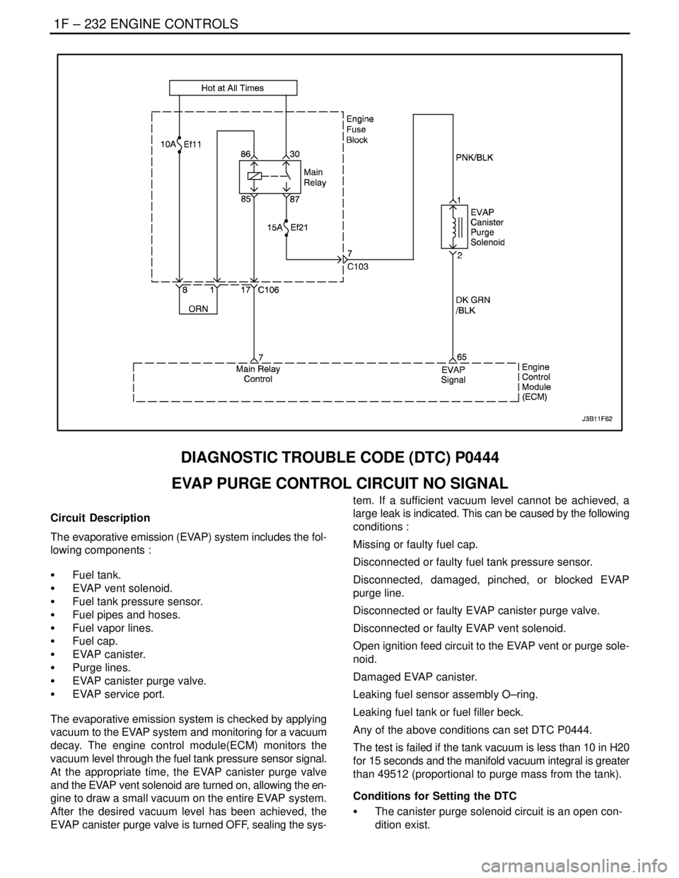
Circuit Description
The evaporative emission (EVAP) system includes the fol-
lowing components :
S Fuel tank.
S EVAP vent solenoid.
S Fuel tank pressure sensor.
S Fuel pipes and hoses.
S Fuel vapor lines.
S Fuel cap.
S EVAP canister.
S Purge lines.
S EVAP canister purge valve.
S EVAP service port.
The evaporative emission system is checked by applying
vacuum to the EVAP system and monitoring for a vacuum
decay. The engine control module(ECM) monitors the
vacuum level through the fuel tank pressure sensor signal.
At the appropriate time, the EVAP canister purge valve
and the EVAP vent solenoid are turned on, allowing the en-
gine to draw a small vacuum on the entire EVAP system.
After the desired vacuum level has been achieved, the
EVAP canister purge valve is turned OFF, sealing the sys-tem. If a sufficient vacuum level cannot be achieved, a
large leak is indicated. This can be caused by the following
conditions :
Missing or faulty fuel cap.
Disconnected or faulty fuel tank pressure sensor.
Disconnected, damaged, pinched, or blocked EVAP
purge line.
Disconnected or faulty EVAP canister purge valve.
Disconnected or faulty EVAP vent solenoid.
Open ignition feed circuit to the EVAP vent or purge sole-
noid.
Damaged EVAP canister.
Leaking fuel sensor assembly O–ring.
Leaking fuel tank or fuel filler beck.
Any of the above conditions can set DTC P0444.
The test is failed if the tank vacuum is less than 10 in H20
for 15 seconds and the manifold vacuum integral is greater
than 49512 (proportional to purge mass from the tank).
Conditions for Setting the DTC
S The canister purge solenoid circuit is an open con-
dition exist.
Page 479 of 2643
ENGINE CONTROLS 1F – 233
DAEWOO V–121 BL4
Action Taken When the DTC Sets
S The Malfunction Indicator Lamp (MIL) will illuminate
after three consecutive trip with a fail.
S The ECM will record operating conditions at the
time the diagnostic fail. This information will be
stored in the Freeze Frame and Failure Records
buffers.
S A history DTC is stored.
Conditions for Clearing the MIL/DTC
S The MIL will turn off after four consecutive ignition
cycles in which the diagnostic runs without a fault.
S A history DTC will clear after 40 consecutive warm–
up cycles without a fault.
S DTC(s) can be cleared by using the scan tool.
S Disconnecting the ECM battery feed for more than
10 seconds.
Diagnostic Aids
Although this DTC is considered a type. A diagnostic, it
acts like a type B diagnostic under certain conditions.
Whenever this diagnostic reports the system has passed,
or if the battery is disconnected, the diagnostic must fail
twice before setting a DTC. The initial failure is not re-ported to the diagnostic executive or displayed on a scan
tool. A passing system always reports to the diagnostic
executive immediately.
Check for the following conditions :
S Missing or damaged fuel cap.
S Missing or damaged O–rings at fuel vapor and
EVAP purge line canister fittings.
S Cracked or punctured EVAP canister.
S Damaged source vacuum line, EVAP purge line,
EVAP vent hose or fuel tank vapor line.
S Poor connection at the ECM. Inspect the harness
connectors for the following conditions.
S Backed–out terminals.
S Improper mating.
S Broken locks.
S Improperly formed.
S Damaged terminals.
S Poor terminal–to–wire connection.
S Damaged harness. Inspect the wiring harness to
the EVAP vent solenoid, EVAP canister purge
valve, and the fuel tank pressure sensor for an in-
termittent open or short circuit.
S Kinked, pinched or plugged vacuum source, EVAP
purge, or fuel tank vapor line. Verify that the lines
are not restricted.
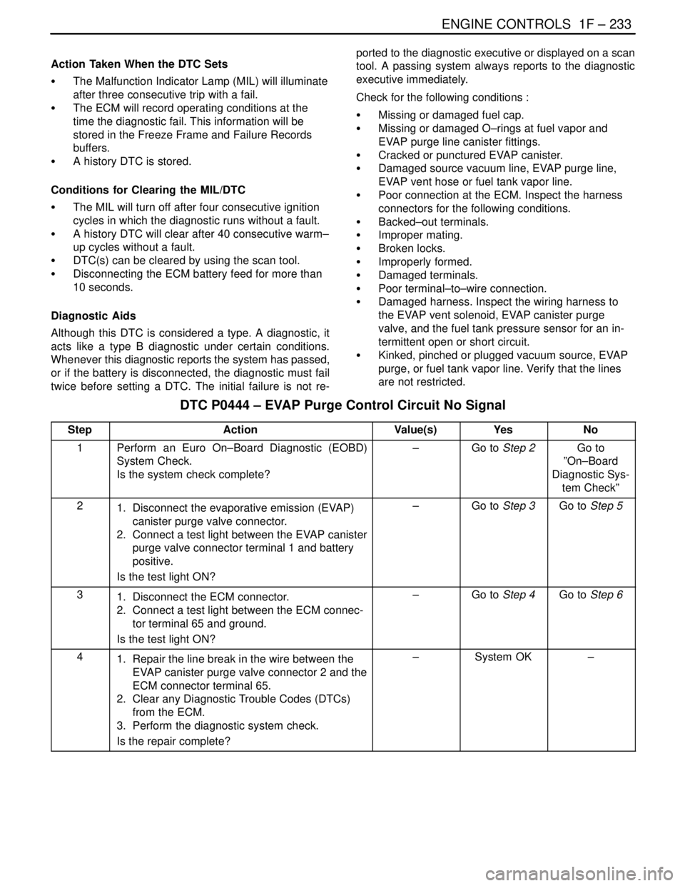
DTC P0444 – EVAP Purge Control Circuit No Signal
StepActionValue(s)YesNo
1Perform an Euro On–Board Diagnostic (EOBD)
System Check.
Is the system check complete?–Go to Step 2Go to
”On–Board
Diagnostic Sys-
tem Check”
21. Disconnect the evaporative emission (EVAP)
canister purge valve connector.
2. Connect a test light between the EVAP canister
purge valve connector terminal 1 and battery
positive.
Is the test light ON?–Go to Step 3Go to Step 5
31. Disconnect the ECM connector.
2. Connect a test light between the ECM connec-
tor terminal 65 and ground.
Is the test light ON?–Go to Step 4Go to Step 6
41. Repair the line break in the wire between the
EVAP canister purge valve connector 2 and the
ECM connector terminal 65.
2. Clear any Diagnostic Trouble Codes (DTCs)
from the ECM.
3. Perform the diagnostic system check.
Is the repair complete?–System OK–