warning DATSUN 210 1979 User Guide
[x] Cancel search | Manufacturer: DATSUN, Model Year: 1979, Model line: 210, Model: DATSUN 210 1979Pages: 548, PDF Size: 28.66 MB
Page 168 of 548
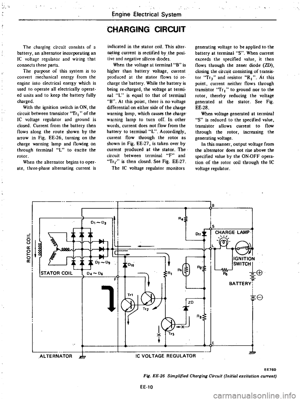
The
charging
circuit
consists
of
a
battery
an
alternator
incorporating
an
IC
voltage
regulator
and
wiring
that
connects
these
parts
The
purpose
of
this
system
is
to
convert
mec
hanka
energy
from
the
engine
into
electrical
energy
which
is
used
to
operate
all
electrically
operat
ed
units
and
to
keep
the
battery
fully
charged
With
the
ignition
switch
in
ON
the
circuit
between
transistor
uTr
I
of
the
lC
voltage
regulator
and
ground
is
closed
Current
from
the
battery
then
flows
along
the
route
shown
by
the
arrOW
in
Fig
EE
26
turning
on
the
charge
warning
lamp
and
flowing
on
through
terminal
L
to
excite
the
rotor
When
the
alternator
begins
to
oper
ate
three
phase
alternating
current
is
ngine
Elect
ical
System
CHARGING
CIRCUIT
indicated
in
the
stator
coil
This
alter
nating
current
is
rectified
by
the
posi
tive
and
negative
silicon
diodes
When
the
voltage
at
terminal
8
is
higher
than
battery
voltage
current
produced
at
the
stator
flows
to
re
charge
the
battery
While
the
battery
is
being
re
charged
the
voltage
at
termi
nal
L
is
equal
to
that
of
terminal
8
At
this
point
there
is
no
voltage
differential
on
either
side
of
the
charge
warning
lamp
which
causes
the
charge
warning
lamp
to
turn
off
In
other
words
current
does
not
flow
from
the
battery
to
terminal
L
Accordingly
current
flow
through
the
rotor
as
shown
in
Fig
EE
27
is
taken
over
by
current
produced
at
the
stator
The
circuit
between
terminal
F
and
Tr
is
then
closed
See
Fig
EE
27
The
IC
voltage
regulator
monitors
generating
voltage
to
be
applied
to
the
battery
at
terminal
S
When
current
exceeds
the
specified
value
it
then
flows
through
the
zener
diode
ZD
closing
the
circ
it
consisting
of
transis
tor
Tr
and
resistor
R1
At
this
point
current
neither
flows
through
transistor
Tr
I
to
ground
nor
to
the
rotor
thereby
reducing
the
voltage
generated
at
the
stator
See
Fig
EE
28
When
voltage
generated
at
terminal
S
is
reduced
to
the
specified
value
transistor
allows
current
to
flow
through
the
rotor
increasing
the
generating
voltage
In
this
manner
output
voltage
from
the
alternator
does
not
rise
above
the
specified
value
by
the
ON
OFF
opera
tion
of
the
rotor
coil
through
the
IC
voltage
regulator
16
L
R
l
I
01
0
ls
CHARGE
LAMP
J
011
L
e
0
u
a
M
e
i
J
0
io
o
IGNITION
a
0
09
SWITC1
R2
El1
STATOR
COIL
04
0
R
F
1
BATTERY
8
ZD
ALTERNATOR
7
I
1
AJ
TI
3
IC
VOLTAGE
REGULATOR
Aa
E
1
7
EE760
Fig
EE
26
Simplified
Charging
Circuit
Initial
excitation
current
EE
10
Page 170 of 548
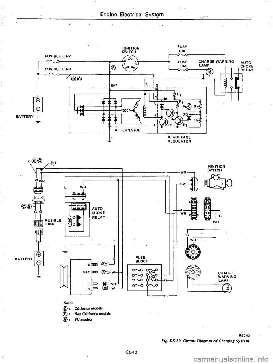
FUSIBLE
LINK
FUSIBLE
LINK
f
BATTERY
@@
V
R
@@
G
G
FUSleLE
ImrnI
LI
NK
MTI
I
En
g
n
l
Electrical
Syst
lOl
IGNITION
SWITCH
FUSE
lOA
o
v
FUSE
lOA
C
V
L@@
BAT
f
L
S
BI
I
I
sl
fRO
L
I
I
F
I
EI
i
K
a
ALTERNATOR
lE
Ie
VOLTAGE
REGULATOR
I
I
L
WR
I
1
d
I
t
J
t
IGNITION
WR
SWITCH
BW
U
0
AUTO
CHOKE
RELAY
G
1
WR
J
I
00
00
gg
1
00
VR
1
E
lDID
I
@
O
BAT
mID
W
J
WR
W
FUSE
BLOCK
CHARGE
WARNING
LAMP
5J
BL
Note
@
V
@
California
models
Non
Qilifomo
18
models
FU
models
Fig
EE
29
Circuit
Dinrswr
EE742
mofCIuJ
Tg
ng
Sy
t
m
EE
12
Page 175 of 548
Engine
Electrical
System
6
Tighten
through
bolts
rfl
Tightening
torque
Through
bolts
60
to
70
kg
cm
52
to
61
in
lb
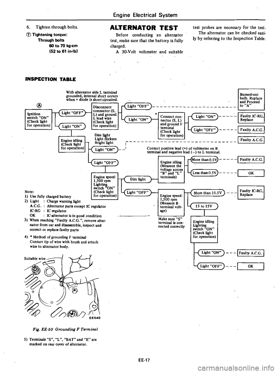
ALTERNATOR
TEST
Before
conducting
an
alternator
test
make
sure
that
the
battery
is
fully
charged
A
30
Volt
voltmeter
and
suitable
INSPECTION
TABLE
With
alternator
aide
L
tenninal
grounded
internal
short
occurs
when
diode
is
short
circuited
@
test
probes
are
necessary
for
the
test
The
alternator
can
be
checked
easi
ly
by
referring
to
the
Inspection
Table
Bumed
out
bulb
Replace
and
Proceed
toUA
Ignition
switch
ON
Check
light
for
operation
Disconnect
Light
OFF
f
Light
OFF
connector
S
L
and
ground
L
lead
wire
Light
ON
Check
light
for
operation
Light
ON
I
Faulty
IC
RG
Replace
Connect
con
nector
S
L
and
ground
F
a1light
Light
OFF
I
FaultyA
C
G
I
Dim
light
for
operation
tf
i
rs
1
I
Faulty
A
C
G
I
Light
ON
I
Contact
positive
lead
of
voltmeter
on
B
lennina
and
negative
lead
to
L
tenninal
Light
ON
1
Engine
idling
Check
light
for
operation
Light
OFF
I
Engine
idling
Measure
the
voltage
across
B
and
L
terminals
Engine
speed
1
500
rpm
Ligh
tin
switch
ON
Check
light
for
operation
r
Dim
light
Light
OFF
Note
1
Use
fully
charged
battery
2
Light
Charge
warning
light
A
C
G
Alternator
parts
except
IC
regu
tor
IC
RG
IC
n
guJator
OK
IC
altemator
is
in
good
condition
3
When
reaching
Faulty
A
C
G
remove
alter
nator
from
car
and
disassemble
inspect
and
correct
or
replace
faulty
parts
Engine
speed
1
500
rpm
Measure
B
terminal
volt
sge
Make
sure
S
terminal
is
con
nected
correctly
4
Method
of
grounding
F
terminal
Contact
tip
of
wire
with
brush
and
attach
wire
to
alternator
body
Suitable
wire
I
Fig
EE
50
Grounding
F
Terminal
5
Terminals
S
L
BA
Tn
and
E
are
marked
on
rear
cover
of
alternator
EEl7
More
thanO
5V
I
Faulty
A
e
G
1
Less
thanO
5V
I
OK
T
Mon
than
15
5V
I
Z
C
RG
I
I3
to
15V
Engine
idling
Lighting
switch
ON
Check
light
for
operation
Light
ON
I
Faulty
A
C
G
I
Light
OFF
I
OK
Page 176 of 548
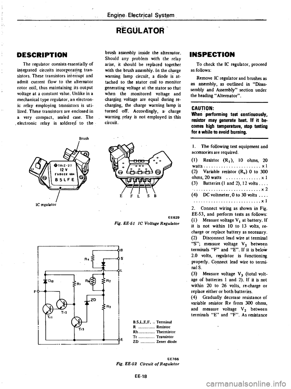
DESCRIPTION
The
regulator
consists
essentially
of
in
egrated
circuits
incorporating
tran
sistors
These
transistors
int
errupt
and
admit
current
flow
to
the
alternator
rotor
coil
thus
maintaining
its
output
voltage
at
a
constant
value
Unlike
in
a
mechanical
type
regulator
an
electron
ic
relay
employing
transistors
is
uti
lized
These
transistors
are
enclosed
in
a
very
compact
sealed
case
The
electronic
relay
is
soldered
to
the
Brush
Ie
regulator
R
J
DIO
F
i
ZD
Tn
Engipe
Electrjcal
Syst
em
REGULATOR
brush
assembly
inside
the
alternator
Should
any
problem
with
the
relay
arise
it
should
be
replaced
together
with
the
brush
assembly
In
the
charge
warning
lamp
circuit
a
diode
is
at
tached
to
the
stator
coil
to
monitor
generating
voltage
at
the
stator
so
that
when
the
monitored
voltage
and
charging
voltage
are
equal
during
re
charging
the
charge
warning
lamp
is
turned
off
Accordingly
a
charge
warning
relay
is
not
employed
in
this
circuit
s
r
t
E
F
L
S
B
EE629
Fig
EE
51
lC
Voltage
RegultJtor
I
B
S
L
I
R
R
E
B
S
L
E
F
Terminal
R
Resistor
Rh
Thermistor
Tr
Transistor
ZD
Zener
diode
EE766
Fig
EE
52
Circuit
of
RegultJtor
EE
18
INSPECTION
To
check
the
IC
regulator
proceed
as
follows
Remove
IC
regulator
and
brushes
as
an
assembly
as
outlined
in
Disas
sembly
and
Assembly
section
under
the
heading
Alternator
CAUTION
When
performing
test
continuously
resistor
may
generate
heat
If
it
be
comes
high
temperature
stop
testing
for
a
while
to
avoid
burning
The
following
test
equipment
and
accessories
are
required
I
Resistor
R
10
ohms
20
watts
x
I
2
Variable
resistor
Rv
0
to
300
ohms
20
watts
x
I
3
Batteries
I
and
2
12
volts
x2
4
DC
voltmeter
0
to
30
volts
x
I
2
Connect
wiring
as
shown
in
Fig
EE
S3
and
perform
tests
as
follows
I
Measure
voltage
VI
at
battery
If
it
is
not
within
10
to
13
volts
re
charge
or
replace
battery
as
necessary
2
Disconnect
lead
wire
at
terminal
s
measure
voltage
V
2
between
terminals
F
and
E
If
it
is
below
2
0
volts
regulator
is
functioning
properly
Connect
lead
wire
to
termi
nalS
3
Measure
voltage
V
3
total
volt
age
of
batteries
I
and
2
If
it
is
not
within
20
to
26
volts
re
charge
or
replace
either
or
both
batteries
4
Gradually
decrease
resistance
of
variable
resistor
Rv
from
300
ohms
and
measure
voltage
V
2
between
terminals
En
and
F
As
resistance
Page 178 of 548
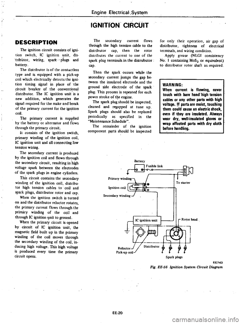
DESCRIPTION
The
ignition
circuit
consists
of
igni
tion
switch
Ie
ignition
unit
dis
tributor
winng
ipark
plugs
and
battery
The
distributor
is
of
the
contactless
type
and
is
equipped
with
a
pick
up
coil
which
electrically
detects
the
igni
tion
timing
signal
in
place
of
the
ircuit
I
rea
r
of
the
conventional
distributor
The
IC
ignition
unit
is
a
new
addition
which
generates
the
signal
required
for
the
make
and
break
of
the
primary
current
for
the
ignition
coil
The
primary
current
is
supplied
by
the
battery
or
alternator
and
flows
through
the
primary
circuit
It
consists
of
the
ignition
switch
primary
winding
of
the
ignition
coil
IC
ignition
unit
and
all
connecting
low
tension
wiring
The
secondary
current
is
produced
by
the
ignition
coil
and
flows
through
the
secondary
circuit
resulting
in
high
voltage
spark
between
the
electrodes
of
the
spark
plugs
in
engine
cylinders
This
circuit
contains
the
secondary
winding
of
the
ignition
coil
distribu
tor
high
tension
cables
to
coil
and
spark
plugs
distributor
rotor
and
cap
When
the
ignition
switch
is
turned
on
and
the
distributor
reluctor
rotates
the
primary
current
flows
through
the
primary
winding
of
the
coil
and
through
IC
ignitionu
nit
to
ground
When
the
primary
circuit
is
opened
by
circuit
of
IC
ignition
unit
the
magnetic
field
built
up
in
the
primary
winding
of
the
coil
moves
through
the
secondary
winding
of
the
coil
in
ducing
high
voltage
This
high
voltage
is
produced
every
time
the
primary
circuit
opens
EngineElect
ical
System
IGNITfON
CIRCUIT
The
secondary
current
flows
through
the
high
tension
cable
to
the
distributor
cap
then
the
rotor
distributes
the
current
to
one
of
the
spark
plug
terminals
in
the
distrubutor
cap
Then
the
spark
occurs
while
the
secondary
current
jumps
the
gap
be
tween
the
insulated
electrode
and
the
ground
side
electrode
of
the
spark
plug
This
process
is
repeated
for
each
power
stroke
of
t
e
engine
The
spark
plug
should
be
inspected
cleaned
and
regapped
at
tune
up
Spark
plugs
should
also
be
replaced
periodically
as
specified
in
the
Maintenance
Schedule
The
remainder
of
the
ignition
component
parti
should
be
inspected
Battery
letink
Primary
winding
1
Ignition
coil
Secondary
winding
J
for
only
their
operation
air
gap
of
distributor
tightness
of
electrical
terminals
and
wiring
condition
Apply
grease
NLGI
consistency
No
I
containing
MaS
or
equivalent
to
distributor
rotor
shaft
as
required
WARNING
When
current
is
flowing
never
touch
with
bare
hand
high
tension
cables
or
any
other
parts
with
high
vollage
If
parts
are
moist
touching
them
could
cause
an
electric
shock
even
if
they
are
insulated
Always
wear
dry
well
insulated
gloves
or
wrap
affected
parts
with
dry
cloth
before
handling
To
starter
EE
20
Ro
or
head
Ul
J
r
Spark
plugs
EE743
Fig
EE
56
Ignition
System
Circuit
Diagram
Page 199 of 548

REMOVAL
It
is
much
easier
to
remove
engine
and
transmission
as
a
single
unit
than
to
remove
alone
After
removal
engine
can
be
separated
from
the
transmission
assembly
WARNING
a
Place
wheel
chocks
in
fronl
of
front
wheels
and
in
rear
of
rear
wheels
b
Be
sure
to
hoist
engine
in
a
safe
manner
c
You
should
not
remove
engine
until
exhaust
system
has
com
pletely
cooled
off
Otherwise
you
may
burn
your
self
and
or
fire
may
break
out
in
fuel
line
Note
Fender
coven
should
be
used
to
protect
car
body
1
Disconnect
battery
ground
cable
from
battery
terminal
and
fusible
link
at
wire
connector
2
Remove
hood
as
follows
CAUTION
Have
an
assistant
help
you
so
as
to
prevent
damage
to
body
I
Mark
hood
hinge
locations
on
hood
to
facilitate
reinstallation
2
Support
hood
by
ltand
and
re
move
bolts
securing
it
to
hood
hinge
being
careful
not
to
let
hood
slip
when
bolts
are
removed
See
Fig
ER
2
3
Remove
hood
from
hood
hinge
f
Il
I
BF133A
Fig
ER
2
Removing
Hood
Remove
under
cover
Drain
radiator
coolant
and
engine
3
4
oil
5
Disconnect
upper
and
lower
hoses
from
radiator
and
disconnect
oil
cooler
hoses
automatic
transmission
only
6
Remove
four
bolts
securing
radia
Engine
Removal
Installation
tor
to
body
and
detach
radiator
after
removing
radiator
shroud
7
Remove
air
cleaner
assembly
from
carburetor
as
follows
1
Remove
fresh
air
duct
from
air
cleaner
2
Remove
hot
air
duct
from
air
cleaner
3
Loosen
air
cleaner
band
bolt
4
Disconnect
air
cleaner
to
air
pump
hose
at
air
cleaner
5
Disconnect
air
cleaner
ta
rocker
cover
hose
at
rocker
cover
6
Disconnect
air
cleaner
to
A
B
valve
hose
at
air
cleaner
7
Disconnect
air
cleaner
to
related
vacuum
hoses
at
air
cleaner
8
Disconnect
accelerator
control
wire
from
carburetor
9
Disconnect
the
following
cables
wires
and
hoses
Wire
to
auto
choke
heater
Wire
to
throttle
opener
cut
solenoid
or
throttle
switch
Wire
to
fuel
cut
solenoid
Wire
to
vacuum
switching
valve
High
tension
cable
between
igni
tion
coil
and
distributor
Battery
cable
to
starter
motor
Wire
to
distributor
Wire
to
thermal
transmitter
Wire
to
alternator
Engine
ground
cable
oil
pressure
switch
and
engine
harness
No
2
See
Fig
ER
3
o
1
Ground
cable
2
Engine
harness
No
2
3
Oil
pressure
switch
Fig
ER
3
EA368
Disconnecting
Cable
and
Wire
Fuel
hose
at
fuel
pump
and
fuel
return
hose
at
connection
Air
pump
air
cleaner
hose
Carbon
canister
hoses
Heater
inlet
and
outlet
hoses
if
so
equipped
ER
3
Vacuum
hose
of
brake
booster
at
intake
manifold
Air
conditioner
equipped
model
10
Remove
compressor
belt
To
remove
loosen
idler
pulley
nut
and
adjusting
bolt
1
Remove
air
pump
2
Remove
compressor
retaining
bolts
and
move
compressor
toward
fender
to
facilitate
removal
of
engine
Nole
Never
discharge
gas
from
com
pressor
while
work
is
being
per
formed
II
Compressor
EA478
Fig
ER
4
Location
of
Air
Compressor
3
Disconnect
vacuum
hose
of
air
conditioner
from
connector
of
intake
manifold
4
Remove
F
i
C
D
actuator
from
bracket
II
Remove
clutch
operating
cylin
der
from
clutch
housing
manual
trans
mission
only
dJ
Tightening
torque
Clutch
operating
cylinder
E
A3
to
clutch
housing
3
1
to
4
1
kg
22
to
30
ft
lbl
Fig
ER
5
Removing
Clutch
Operating
Cylinder
Page 200 of 548
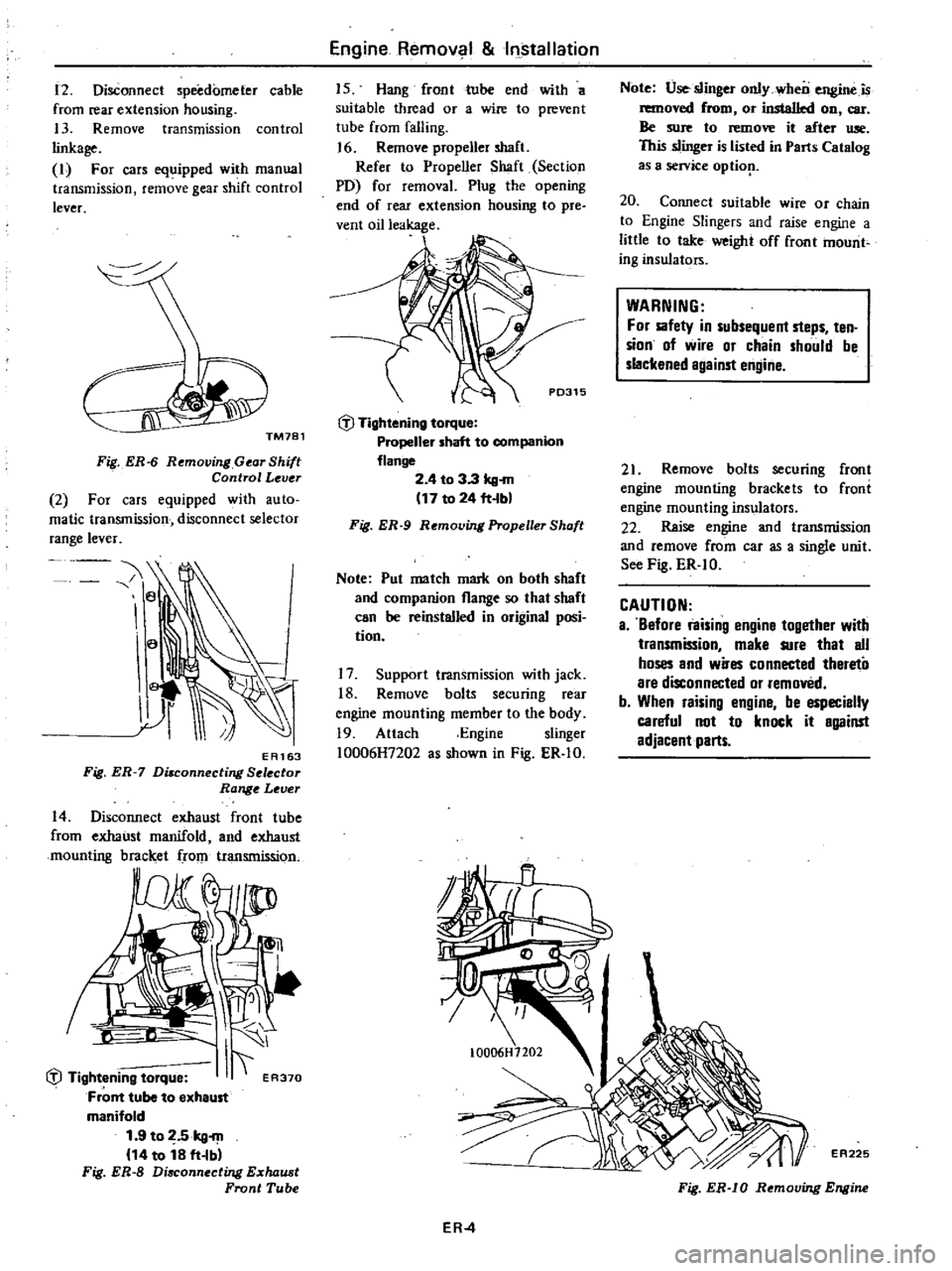
12
Disconnect
speedometer
cable
from
rear
extension
housing
13
Remove
transmission
control
linkage
I
For
cars
equipped
with
manual
transmission
remove
gear
shift
control
lever
Fig
ER
6
Removing
Gear
Shift
Control
Lever
2
For
cars
equipped
with
auto
matic
transmission
disconnect
selector
range
lever
e
a
EA163
Fig
ER
7
Di8connecting
Selector
Range
Lever
14
Disconnect
exhaust
front
tube
from
exhaust
manifold
and
exhaust
mounting
bracket
rom
transmission
I
liJ
Tightening
torque
I
ER370
Front
tube
to
exheust
manifold
1
9
to
2
5kg
m
14
to
18
ft
Ibl
Fig
ER
S
Disconnecting
E
chaust
Front
Tube
Engine
Remov
1
Installation
15
Hang
front
tube
end
with
a
suitable
thread
or
a
wire
to
prevent
tube
from
falling
J
6
Remove
propeller
shaft
Refer
to
Propeller
Shaft
Section
PO
for
removal
Plug
the
opening
end
of
rear
extension
housing
to
pre
vent
oil
leakage
P0315
liJ
Tightening
torque
Propeller
shaft
to
companion
flange
2
4
to
3
3
kg
m
17
to
24
ft
bl
Fig
ER
9
Removing
Propeller
Shaft
Note
Pul
me
tch
mark
on
both
shaft
and
companion
flange
so
that
shoft
can
be
reinstalled
in
original
posi
tion
17
Support
transmission
with
jack
18
Remove
bolts
securing
rear
engine
mounting
member
to
the
body
19
Attach
Engine
slinger
10006H7202
as
shown
in
Fig
ER
IO
Note
Use
slinger
only
wheo
engine
is
removed
from
or
installed
on
car
Be
sure
to
remove
it
efter
Ulle
This
slinger
is
listed
in
Parts
Cet
log
as
a
service
optiop
20
Connect
suitable
wire
or
chain
to
Engine
Slingers
and
raise
engine
a
little
to
take
weight
off
front
mount
ing
insulators
WARNING
For
sofety
in
subsequent
steps
ten
sion
of
wire
or
chain
should
be
slackened
against
engine
21
Remove
bolts
securing
front
engine
mounting
brackets
to
froni
engine
mounting
insulators
22
Reise
engine
and
transmission
and
remove
from
car
as
a
single
unit
See
Fig
ER
IO
CAUTION
a
Before
raising
engine
10gether
with
transmission
make
sure
that
all
hoses
and
wires
connected
thereto
are
disconnected
or
removed
b
When
raising
engine
be
especially
careful
not
to
knock
it
against
adjacent
parts
ER
4
EA225
Fig
ER
IO
Removing
Engine
Page 354 of 548
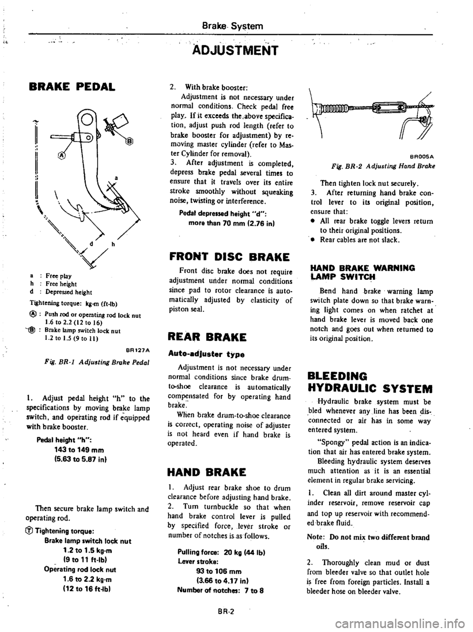
BRAKE
PEDAL
a
a
Fr
play
h
Free
height
d
Depressed
height
Tightening
torque
Icg
m
ft
tb
@
@
Push
rod
or
operating
rod
lock
nut
1
6
to
2
2
12
to
16
Brake
lainp
switch
lock
nut
1
2
to
I
5
9
to
11
BR121A
Fig
BR
1
Adjusting
Broke
Pedal
I
Adjust
pedal
height
h
to
the
specifications
by
moving
brake
lamp
switch
and
operating
rod
if
equipped
with
brake
booster
Pedal
height
h
143
to
149
mm
5
63
to
5
87
inl
Then
secure
brake
lamp
switch
and
operating
rod
C
l
Tightening
tOlque
Blake
lamp
witch
lock
nut
1
2
to
1
5
kg
m
9
to
11
ft
lb
Operating
lad
lock
nut
1
6
to
2
2
kg
m
12
to
16
ft
b
Brake
System
ADJUSTMENT
2
With
brake
booster
Adjustment
is
not
necessary
under
normal
conditions
Check
pedal
free
play
If
it
exceeds
the
above
specifica
tion
adjust
push
rod
length
refer
to
brake
booster
for
adjustment
by
re
moving
master
cylinder
rerer
to
Mas
ter
Cylinder
for
removal
3
After
adjustment
is
completed
depress
brake
pedal
several
times
to
ensure
that
it
travels
over
its
entire
stroke
smoothly
without
squeaking
noise
twisting
or
interference
Pedal
depr
d
Might
d
more
than
70
mm
2
76
in
FRONT
DISC
BRAKE
Front
disc
brake
does
not
require
adjustment
under
normal
conditions
since
pad
to
rotor
clearance
is
auto
malically
adjusted
by
elasticity
of
piston
seal
REAR
BRAKE
Auto
edJuster
type
Adjustment
is
not
necessary
under
normal
conditions
since
brake
drum
t
shoe
clearance
is
automatically
compensated
for
by
operating
hand
brake
Wlien
brake
drum
to
shoe
clearance
is
correct
operating
noise
of
adjuster
is
not
heard
even
if
hand
brake
is
operated
HAND
BRAKE
I
Adjust
rear
brake
shoe
to
drum
clearance
before
adjusting
hand
brake
2
Turn
turnbuckle
so
that
when
hand
brake
control
lever
is
pulled
by
specified
force
lever
stroke
or
number
of
notches
is
as
follows
Pulling
fOil
20
kg
44
Ib
lever
stroke
93
to
106
mm
3
66
to
4
17
in
Numbel
of
notches
7
to
8
BR
2
f
BAQ05A
Fig
BR
2
Adjusting
Hand
Brake
Then
tighten
lock
nut
securely
3
After
returning
hand
brake
con
trol
lever
to
its
original
position
ensure
that
e
All
rear
brake
toggle
levers
return
to
their
original
positions
Rear
cables
are
not
slack
HAND
BRAKE
WARNING
LAMP
SWITCH
Bend
hand
brake
warning
lamp
switch
plate
down
so
that
brake
warn
ing
light
comes
on
when
ratchet
at
hand
brake
lever
is
moved
back
one
notch
and
goes
out
when
returned
to
its
original
position
BLEEDING
HYDRAULIC
SYSTEM
Hydraulic
brake
system
must
be
bled
whenever
any
line
has
been
dis
connected
or
air
has
in
some
way
entered
system
Spongy
pedal
action
is
an
indica
tion
that
air
has
entered
brake
system
Bleeding
hydraulic
system
deserves
much
attention
as
it
is
an
essential
element
in
regular
brake
servicing
Clean
all
dirt
around
master
cyl
inder
reservoir
remove
reservoir
cap
and
top
up
reservoir
with
recommend
edbrake
fluid
Note
Do
not
mix
two
different
brand
oils
2
Thoroughly
clean
mud
or
dust
from
bleeder
valve
so
that
outlet
hole
is
free
from
foreign
particles
Install
a
bleeder
hose
on
bleeder
valve
Page 357 of 548
REMOVAL
I
Disconnect
wiring
to
brake
fluid
level
gauge
2
Disconnect
front
and
rear
brake
tubes
from
master
cylinder
CAUTION
When
removing
brake
tubes
use
suitable
tube
wrench
Never
use
open
end
or
edjustllble
wrench
Note
When
disconnecting
brake
tubes
be
sure
to
use
a
container
to
receive
draining
brake
fluid
Use
of
raga
is
also
suggested
to
keep
adjacent
perts
and
area
clean
3
Remove
master
cylinder
securing
nut
Master
cylinder
can
then
be
taken
out
DISASSEMBLY
1
Remove
reservoir
caps
and
filtern
and
drain
out
brake
fluid
2
Pry
off
stopper
ring
using
a
screwdriver
3
Remove
stopper
screw
and
take
out
stopper
primary
piston
assembly
spring
and
secondary
piston
assembly
in
the
order
shown
Note
Discard
caps
if
they
are
reo
moved
from
piston
assemblies
and
use
new
ones
4
Unscrew
pluga
to
gain
access
to
check
valve
for
disassembling
Note
a
Never
detach
reservoir
tanks
If
they
are
removed
for
any
reason
discard
them
and
install
new
ones
b
Do
not
remove
or
disassemble
brake
fluid
level
gauge
INSPECTION
Thoroughly
clean
all
parts
in
a
suitable
solvent
and
check
them
for
wear
or
damage
Replace
any
part
that
is
faulty
Brake
System
CAUTION
Use
brake
fluid
to
clean
Never
use
mineral
oil
I
Check
cylinder
and
pistons
for
evidence
of
abnonnal
wear
or
damage
Replace
if
found
faulty
2
Check
piston
to
cylinder
clear
ance
If
it
exceeds
the
specified
value
replace
either
piston
or
cylinder
Piston
to
cylinder
clearance
less
than
0
15
mm
0
0059
in
3
Check
springs
for
weakness
fatigue
or
damage
Replace
if
neces
sary
4
When
master
cylinder
is
disas
sembled
be
sure
to
discard
caps
and
valves
Replace
any
other
parts
which
show
evidence
of
deformation
wear
or
other
damage
S
Replace
damaged
oil
reservoirs
and
caps
ASSEMBLY
Assemble
master
cylinder
following
the
reverse
procedure
of
disassembly
paying
particular
attention
to
the
fol
lowing
note
Note
a
Replace
gaskets
and
packing
with
new
ones
b
Apply
brake
fluid
or
rubber
grease
to
sliding
contact
surface
of
parts
to
facilitate
assembly
of
master
cylinder
c
The
brake
master
cylinder
is
avail
able
in
both
NABCO
make
and
TOKICO
make
There
is
no
inter
changeability
of
repair
kits
or
com
ponent
parts
between
NABCO
and
TOKlCO
makes
When
replacing
the
repair
kit
or
component
parts
ascertain
the
brand
of
the
brake
master
cylinder
body
Be
sure
to
use
parts
of
the
same
make
as
the
fonner
ones
INSTALLATION
Install
master
cylinder
following
the
reverse
procedure
of
removal
After
installation
bleed
brake
system
BR
5
CAUTION
When
installing
Flare
Nut
6694310000
brake
tubes
use
Torque
Wrench
CiJ
Tightening
torque
Brake
master
cylinder
securing
nut
0
8
to
t
1
kg
m
5
8
to
8
0
ft
lb
Brake
tube
flare
nut
1
5
to
1
8
kg
m
11
to
13
ft
b
BRAKE
FLUID
LEVEL
GAUGE
Inspection
I
Disengage
hand
brake
control
lever
2
Raise
cap
and
make
sure
that
hand
brake
warning
lamp
goes
on
when
float
comes
into
contact
with
stopper
BRAKE
LINE
REMOVAL
I
Remove
flare
nuts
on
both
ends
and
remove
retainers
and
clips
CAUTION
When
removing
brake
tubes
and
hoses
use
suitable
tube
wrench
Never
use
open
end
or
adjustable
wrench
2
To
remove
brake
hose
first
re
move
flare
nut
securing
brake
tube
to
brake
hose
and
withdraw
lock
spring
End
of
hose
can
then
be
removed
from
bracket
Next
remuve
brake
hose
Do
not
twist
brake
hose
INSPECTION
Check
brake
lines
tubes
and
hoses
for
evidence
of
cracks
deterioration
or
other
damage
Replace
any
faulty
parts
Page 362 of 548
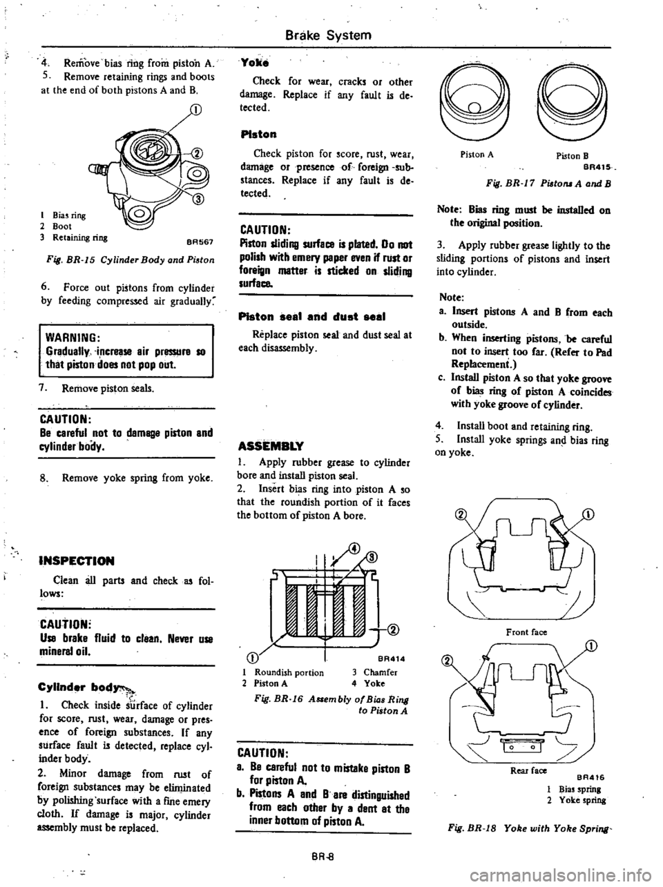
Remove
bias
ring
from
piston
A
S
Remove
retaining
rings
and
boots
at
the
end
of
both
pistons
A
and
B
I
Biuring
2
Boot
3
Retaining
ring
BA567
Fig
BR
15
Cylinder
Body
and
Pi
tan
6
Force
out
pistons
from
cylinder
by
feeding
compressed
air
gradually
WARNING
Gradually
increase
air
pressurs
10
that
piston
does
not
pop
out
7
Remove
piston
seals
CAUTION
Be
careful
not
to
damBlle
piston
and
cylinder
boily
8
Remove
yoke
spring
from
yoke
INSPECTION
Clean
au
parts
and
check
u
fol
lows
CAutiON
Use
brake
fluid
to
claan
Never
use
minersl
oil
Cylinder
bod
1
Check
inside
surface
of
cylinder
for
score
rust
wear
damage
or
pres
ence
of
foreign
substances
If
any
surface
fault
is
detected
replace
cyl
inder
body
2
Minor
damage
from
rust
of
foreign
substances
may
be
eliminated
by
polishing
surface
with
a
fme
emery
cloth
If
damage
is
major
cylinder
assembly
must
be
replaced
Brake
System
Yoke
Check
for
wear
cracks
or
other
damage
Replace
if
any
fault
is
de
tected
PIston
Check
piston
for
score
rust
wear
damage
orpresenco
of
foreign
sub
stances
Replace
if
any
fault
is
de
tected
CAUTION
Piston
sliding
surface
is
plated
00
not
polish
with
emery
peper
even
if
rust
or
foreign
matter
is
sticked
on
sliding
surface
PIston
seal
end
dust
seel
Replace
piston
seal
and
dust
seal
at
each
dis
mbly
ASSEMBLY
1
Apply
rubber
grease
to
cylinder
bore
and
install
piston
seal
2
Insert
bias
ring
into
piston
A
so
that
the
roundish
portion
of
it
faces
the
bottom
of
piston
A
bore
I
ID
J
if
C
jt
11
e
1
@
I
j
BA
I
Roundish
portion
3
Chamfer
2
Piston
A
4
Yoke
Fig
BR
16
A
embly
af
Bia
Ring
to
Piston
A
CAUTION
a
Be
careful
not
to
mistaka
piston
B
for
piston
A
b
Pistons
A
and
B
are
distinguished
from
each
other
by
a
dent
at
the
inner
bottom
of
piston
A
BR
8
Piston
A
Piston
B
BR41S
Fig
BR
17
Pisto
A
and
B
Note
Bias
ring
must
be
instaDed
on
the
original
position
3
Apply
rubber
grease
lightly
to
the
sliding
portions
of
pistons
and
insert
into
cylinder
Note
a
Insert
pistons
A
and
B
from
each
outside
b
When
inserting
pistons
be
careful
not
to
insert
too
far
Refer
to
Pad
Replacemeni
c
Install
piston
A
so
that
yoke
groove
of
bias
ring
of
piston
A
coincides
with
yoke
groove
of
cylinder
4
Instau
boot
and
retaining
ring
S
Install
yoke
springs
an
bias
ring
on
yoke
Front
face
1
1
0
Rear
face
BA416
1
Bias
Sprinl
2
Yoke
spring
Fig
BR
18
Yoke
with
Yoke
Spring