warning DATSUN 210 1979 Service Manual
[x] Cancel search | Manufacturer: DATSUN, Model Year: 1979, Model line: 210, Model: DATSUN 210 1979Pages: 548, PDF Size: 28.66 MB
Page 4 of 548
FO
REWO
RD
TJili
service
manual
has
been
prepared
for
the
purpose
of
assisting
service
personnel
of
authorized
NISSAN
DATSUN
dealerS
in
providing
effective
service
and
maintenance
of
the
1979
DATSU
II210
Since
proper
maintenance
and
service
are
absolutely
essential
in
satisfying
the
DATSUN
owners
this
manu31
should
be
kept
in
a
handy
place
for
ready
reference
and
should
be
carefully
studied
t
This
manual
includes
procedures
for
maintenance
adjustments
minor
service
operations
removal
and
instaUation
and
for
rli
mblyand
assembly
of
components
Some
of
these
service
opemtions
require
the
of
Special
Tools
especially
designed
for
effective
performance
of
service
operations
The
special
tools
are
presented
at
the
end
of
each
section
As
you
read
through
the
l
lIintenance
procedures
inthis
service
m3
lual
y
lu
w
ll
occasionally
come
across
paragraphs
headed
NOTE
CAUTION
or
WARNING
A
NOTE
is
supplemental
information
that
is
important
to
a
particular
procedure
CAUTION
and
WARNING
warn
of
steps
that
must
be
fonowed
to
prevent
damage
to
some
part
of
the
car
and
or
personal
injury
The
Quick
Reference
Index
on
the
first
page
enables
the
user
to
quickly
locate
the
desired
section
At
the
beginning
of
each
individual
section
is
a
table
of
contents
which
gives
the
page
mimber
on
which
each
major
subject
begins
An
information
illustrations
and
specifications
contained
in
this
manual
are
based
on
the
latest
product
information
available
at
the
time
of
publication
approval
If
your
DATSUN
model
differs
from
the
specificationS
contained
in
this
manual
consult
your
NISSAN
DA
TSUN
dealer
for
information
Rights
for
alteration
at
any
time
of
specifications
and
methods
are
reserved
liability
for
any
personal
injury
or
property
damage
occasioned
by
the
use
of
this
service
manual
in
effecting
maintenance
or
repair
of
Y
1
r
DATSUN
is
in
no
way
assumed
by
Nissan
Motor
Co
td
Accordingly
anyone
using
a
service
procedure
or
tool
which
is
not
specifically
recommended
by
NISSAN
must
first
completely
satisfy
himself
that
neither
his
safety
nor
the
car
s
safety
will
be
jeopaiiliiedby
the
service
method
selected
NISSAN
MOTOR
Co
lTD
17
1
G11ZlI6
chomo
chuD
kil
TokyO
l04
J
n
@
1978
N1SSAN
MOTOR
CO
LTD
Printed
in
Japan
Not
to
be
reproduced
in
whole
or
in
part
without
the
prior
writtenpermisUon
of
Nissan
Motor
Company
Ltd
Tokyo
Japan
Page 13 of 548
General
Information
LIFTING
POINTS
AND
TOWING
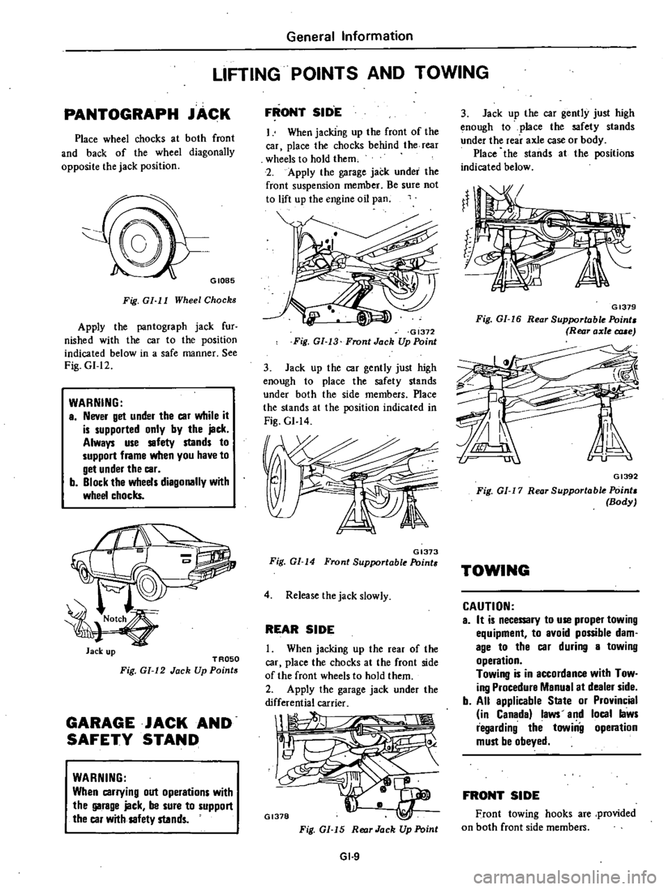
PANTOGRAPH
JACK
Place
wheel
chocks
at
both
front
and
back
of
the
wheel
diagonally
opposite
the
jack
position
GIOB5
Fig
GI
I
I
Wheel
Chocks
Apply
the
pantograph
jack
fur
nished
with
the
car
to
the
position
indicated
below
in
a
safe
manner
See
Fig
GI
12
WARNING
a
Never
get
under
the
car
while
it
is
supported
only
by
the
jack
Always
use
safety
stands
to
support
frame
when
you
have
to
get
under
the
car
b
Block
the
wheels
diagonally
with
wheel
chocks
Jack
up
TROSO
Fig
GI
12
Jack
Up
Points
GARAGE
JACK
AND
SAFETY
STAND
WARNING
When
carrying
out
operations
with
the
garage
jack
be
sure
to
support
the
car
with
safety
stands
FRONT
SID
E
I
When
jacking
up
the
front
of
the
car
place
the
chocks
behind
the
rear
wheels
to
hold
them
2
Apply
the
garage
jack
under
the
front
suspension
member
Be
sure
not
to
lift
up
the
engine
oil
pan
GI372
Fig
GI
13
Front
Jack
Up
Point
3
Jack
up
the
car
gently
just
high
enough
to
place
the
safety
stands
under
both
the
side
members
Place
the
stands
at
the
position
indicated
in
Fig
GI
14
GI373
Fig
GI
14
Front
Supportable
Point
4
Release
the
jack
slowly
REAR
SIDE
When
jacking
up
the
rear
of
the
car
place
the
chocks
at
the
front
side
of
the
front
wheels
to
hold
them
2
Apply
the
garage
jack
under
the
differential
carrier
1
1
Il
GI378
Fig
GI
15
Rear
Jack
Up
Point
GI
9
3
Jack
up
the
car
gently
just
high
enough
to
place
the
safety
stands
under
the
rear
axle
case
or
body
Place
the
stands
at
the
positions
indicated
below
GI379
Fig
GI
16
Rear
Supportable
Point
Rear
axle
c
rue
GI392
Fig
01
17
Rear
Supportable
Point
Body
TOWING
CAUTION
a
It
is
necemry
to
use
proper
towing
equipment
to
avoid
possible
dam
age
to
the
car
during
a
towing
operation
Towing
is
in
accordance
with
Tow
ing
Procedure
Manual
at
dealer
side
b
All
applicable
State
or
Provincial
in
Canada
laws
and
local
laws
regarding
the
towiilg
operation
must
be
obeyed
FRONT
SIDE
Front
towing
hooks
are
provided
on
both
front
side
members
Page 19 of 548
sion
pressure
chances
are
that
piston
rings
are
worn
or
damaged
2
If
pressure
stays
low
the
likeli
hood
is
that
valve
is
sticking
or
seating
Engine
Tune
up
improperly
3
If
cylinder
compression
in
any
two
adjacent
cylinders
is
low
and
if
adding
oil
does
not
help
the
compres
sion
there
is
leakage
past
the
gasketed
surface
Oil
and
water
in
combustion
cham
bers
can
result
from
this
problem
IGNITION
AND
FUEL
SYSTEM
CHECKING
BATTERY
I
Remove
six
vent
plugs
and
check
electrolyte
level
in
each
battery
cell
If
necessary
pour
distilled
water
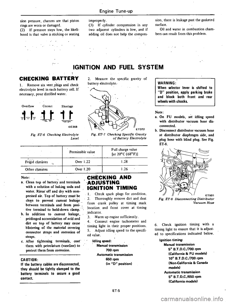
Overflow
Correct
Shortage
t
t
j
t
t
t
EE358
Fig
ET
6
Checking
Electrolyte
Level
2
Measure
the
specific
gravity
of
battery
electrolyte
E
T372
Fig
ET
7
Checking
Specific
Gravity
of
Battery
Electrolyte
Over
1
22
Full
charge
value
at
200C
680F
1
28
1
26
Permissible
value
Frigid
climates
Other
climates
Note
a
Clean
top
of
battery
and
terminals
with
a
solution
of
baking
soda
and
water
Rinse
off
and
dry
with
com
pressed
air
Top
of
battery
must
be
c1
n
to
prevent
current
leakage
between
terminals
and
from
posi
tive
terminal
to
hold
down
clamp
b
In
addition
to
current
leakage
prolonged
accumulation
of
acid
and
dirt
on
top
of
hattery
may
cause
blistering
of
the
material
covering
ronnector
straps
and
rorrosion
of
straps
c
Afte
r
tightening
terminals
coat
them
with
petrolatum
vaseline
to
protect
them
from
corrosion
CAUTION
If
the
battery
cables
are
disconnected
they
should
be
tightly
clamped
to
the
battery
terminals
to
secure
a
good
contact
Over
I
20
CHECKING
AND
ADJUSTING
IGNITION
TIMING
Check
spark
plugs
for
condition
2
Thoroughly
remove
dirt
and
dust
from
crank
pulley
at
timing
mark
location
and
front
cover
at
timing
indicator
3
Warm
up
engine
sufficiently
4
Connect
engine
tachometer
and
timing
light
in
their
proper
positions
5
Adjust
idling
speed
to
the
specifi
ed
value
Idling
speed
Manual
transmission
700
pm
Automatic
transmission
6S0
rpm
in
0
position
ET
S
WARNING
When
selector
lever
is
shifted
to
0
position
apply
parking
brake
and
block
both
front
and
rear
wheels
with
chocks
Note
a
On
FU
models
set
idling
speed
with
distributor
vacuum
hose
dis
connected
b
Disconnect
distributor
vacuum
hose
at
distributor
diaphragm
side
and
plug
hose
with
blind
plug
See
Fig
ET
8
ET501
Fig
ET
B
Disconnecting
Distributor
Vacuum
Hose
6
Check
ignition
timing
with
a
timing
light
to
ensure
that
it
is
adjust
ed
to
specifications
indicated
below
Ignition
timing
Manual
transmission
SO
B
T
0
C
f700
rpm
California
FU
models
100
B
T
0
C
f700
pm
Non
California
Canada
models
Automatic
transmission
SO
B
T
0
C
f6S0
rpm
California
models
Page 21 of 548
CHECKING
AND
ADJUSTING
CARBURETOR
IDLE
RPM
AND
MIXTURE
RATIO
WARNING
a
0
n
a
utomatic
transmission
models
checks
should
be
per
formed
with
the
lever
shifted
to
the
0
position
Be
sure
to
engage
parking
brake
and
to
lock
both
front
and
rear
wheels
with
wheel
chocks
b
Oepress
brake
pedal
while
ac
celerating
the
engine
to
prevent
forward
surge
of
car
c
After
idle
adjustment
has
been
made
shift
the
lever
to
the
N
or
P
positfon
and
remove
wheel
chocks
CAUTION
00
not
attempt
to
screw
the
idle
adjusting
screw
down
completely
00
ing
so
could
cause
damage
to
tip
which
in
turn
will
tend
to
cause
malfunctions
Note
a
When
measuring
CO
percentage
in
sert
probe
into
tail
pipe
more
than
40
cm
15
7
in
b
In
thee
case
of
air
conditioner
e
quipped
models
the
idle
adjust
ment
should
be
carried
out
while
the
air
conditioner
is
OFF
c
When
making
idle
adjustment
do
not
removt
air
cleaner
CO
Idle
adJustment
with
CO
meter
Idle
mixture
adjustment
requires
the
use
of
a
CO
meter
especially
for
California
models
When
preparing
to
adjust
idle
mixture
it
is
essential
to
have
the
meter
thoroughly
warmed
up
and
calibrated
1
Check
carburetor
pipes
for
proper
connection
2
Warm
up
engine
until
water
tern
perature
indicator
points
to
the
middle
of
gauge
The
procedure
to
warm
up
J
Engine
Tune
up
engine
is
not
specifically
recom
mended
Either
driving
car
or
operat
ing
engine
at
no
load
will
be
good
3
Make
sure
that
water
temperature
indicator
points
to
the
middle
Further
keep
engine
running
at
about
2
000
rpm
for
about
5
minutes
without
applying
load
to
engine
in
order
to
stabilize
engine
condition
Engine
hood
should
be
open
4
Run
engine
for
about
10
minutes
at
idling
speed
During
this
10
minutes
proceed
as
described
in
steps
5
to
9
below
5
I
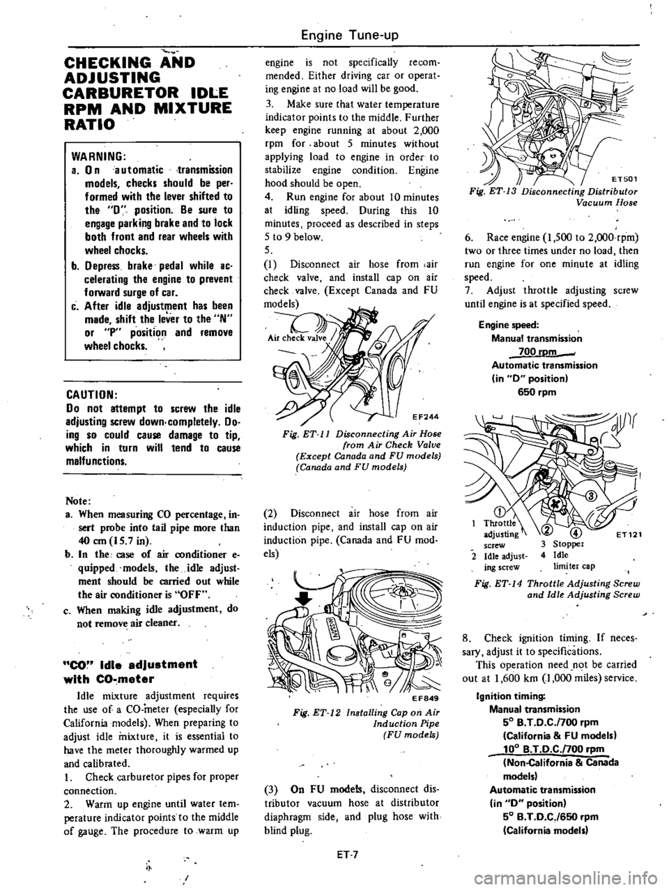
Disconnect
air
hose
from
air
check
valve
and
install
cap
on
air
check
valve
Except
Canada
and
FU
models
EF244
Fig
ET
11
Disconnecting
Air
Hose
from
Air
Check
Valve
Except
Canada
and
FU
models
Canada
and
FU
models
2
Disconnect
air
hose
from
air
induction
pipe
and
install
cap
on
air
induction
pipe
Canada
and
FU
mod
els
EF849
Fig
ET
12
Installing
Cap
on
Air
Induction
Pipe
FU
models
3
On
FU
models
disconnect
dis
tributor
vacuum
hose
at
distributor
diaphragm
side
and
plug
hose
with
blind
plug
ET
7
ET501
Fig
ET
13
Disconnecting
Distributor
Vacuum
Hose
6
Race
engine
I
500
to
2
OOO
rpm
two
or
three
times
under
no
load
then
run
engine
for
one
minute
at
idling
speed
7
Adjust
throttle
adjusting
screw
until
engine
is
at
specified
speed
Engine
speed
Manual
transmission
700
rDm
Automatic
transmission
in
0
position
650
rpm
2
Fig
ET
14
Throttle
Adjusting
Screw
and
Idle
Adjusting
Screw
8
Check
ignition
timing
If
neces
sary
adjust
it
to
specifications
This
operation
need
n
t
be
carried
out
at
1
600
km
1
000
miles
service
Ignition
timing
Manual
transmission
50
B
T
0
C
f700
rpm
California
FU
models
100
B
T
O
C
noo
rpm
Non
California
Canada
models
Automatic
transmission
in
0
position
50
B
T
0
CJ650
rpm
California
model
Page 24 of 548
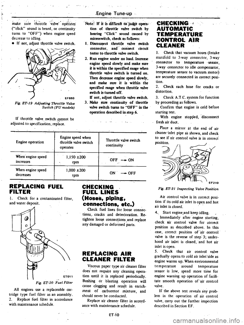
make
sure
throttle
valve
operates
click
sound
is
heard
or
continuity
turns
to
OFF
when
engine
speed
decrease
to
idling
If
not
adjust
throttle
valve
switch
Fig
ET
19
AdjlUting
Throttle
V
ve
Switch
FU
models
If
throttle
valve
switch
g1f1not
be
adjusted
to
specification
replace
Engine
Tune
up
Note
If
it
is
difrlCUlt
to
judge
open
tion
of
throttle
valve
switch
by
hearing
Click
sound
caused
by
microswitch
check
as
follows
1
DiscollI
ecl
throttle
va1ve
switch
ronnector
and
connect
circuit
tester
to
throttle
va1ve
switch
2
Run
engine
under
no
load
Increase
engine
speed
slowly
and
make
sure
it
is
within
the
specified
range
when
throttle
valve
switch
is
turned
on
Then
decrease
engine
speed
slowly
and
make
sure
it
is
within
the
specified
range
when
throttle
va1ve
switch
is
turned
off
If
not
adjust
throttle
valve
switch
3
Make
sure
continuity
of
throttle
vaIve
switch
turns
to
OFF
in
the
operation
desaihed
in
step
6
Engine
operation
Engine
speed
when
throttle
valve
switch
operates
Throttle
valve
switch
continuity
When
engine
speed
increases
1
150
i200
rpm
1
000
1
200
rpm
When
engine
speed
decreases
REPLACING
FUEL
FILTER
I
Check
for
a
contaminated
filter
and
water
deposit
0
9
ET011
Fig
ET
20
Fuel
Filter
All
engines
use
a
replaceable
car
tridge
type
fuel
filter
as
an
assembly
2
Replace
fuel
filter
in
accordance
with
maintenance
schedule
OFF
ON
ON
OFF
CHECKING
FUEL
LINES
Hoses
piping
connections
etc
Check
fuel
lines
for
loose
connec
tions
cracks
and
deterioration
Re
tighten
loose
connections
and
replace
any
damaged
or
deformed
parts
REPLACING
AIR
CLEANER
FILTER
Viscous
paper
type
air
cleaner
filter
does
not
require
any
cleaning
opera
tion
until
it
is
replaced
periodically
Sushing
or
blasting
operation
will
cause
clogging
and
result
in
enrich
ment
of
carburetor
mixture
and
should
never
be
conducted
Replace
air
cleaner
filter
in
accord
ance
with
maintenance
schedule
ET
10
CHECKING
AUTOMATIC
TEMPERATURE
CONTROl
AiR
CLEANER
I
Check
that
vacuum
hoses
Intake
manifold
to
3
way
connector
3
way
connector
to
temperature
sensor
3
way
connector
to
idle
compensator
temperature
sensor
to
vacuum
motor
are
securely
connected
in
C9rrect
posi
tion
2
Check
each
hose
for
cracks
or
distortion
3
Check
A
T
C
system
for
function
by
proceeding
as
follows
ConfIrm
that
engine
is
cold
before
starting
test
With
engine
stopp
d
distonnect
fresh
air
duct
Place
a
mirror
at
the
end
of
air
c1eaner
inlet
pipe
as
shown
and
check
to
see
if
air
control
valve
is
in
correct
pOsition
2J
v
7
EF210
Fig
ET
21
Inspecting
Valve
Position
Air
control
va
ve
is
in
correct
posi
tion
if
its
cold
air
inlet
is
open
and
hot
air
inlet
is
closed
4
Start
engine
and
keep
idling
Immediately
after
engine
starting
check
air
control
valve
for
correCt
position
as
described
above
In
this
case
correct
position
of
air
control
valve
is
the
reverse
of
step
3
under
hood
air
inlet
is
closed
and
hot
air
inlet
is
open
5
Check
that
air
control
valve
gradually
opens
to
cold
air
inlet
side
as
engine
warms
up
When
environmental
temperature
around
temperature
sensor
is
low
spend
more
time
for
engine
warning
up
operation
of
facili
tate
smooth
operation
of
air
control
valve
If
the
above
test
reveals
any
prob
lem
in
the
operation
of
air
control
valve
carry
out
the
further
inspection
described
in
Section
EF
Page 41 of 548
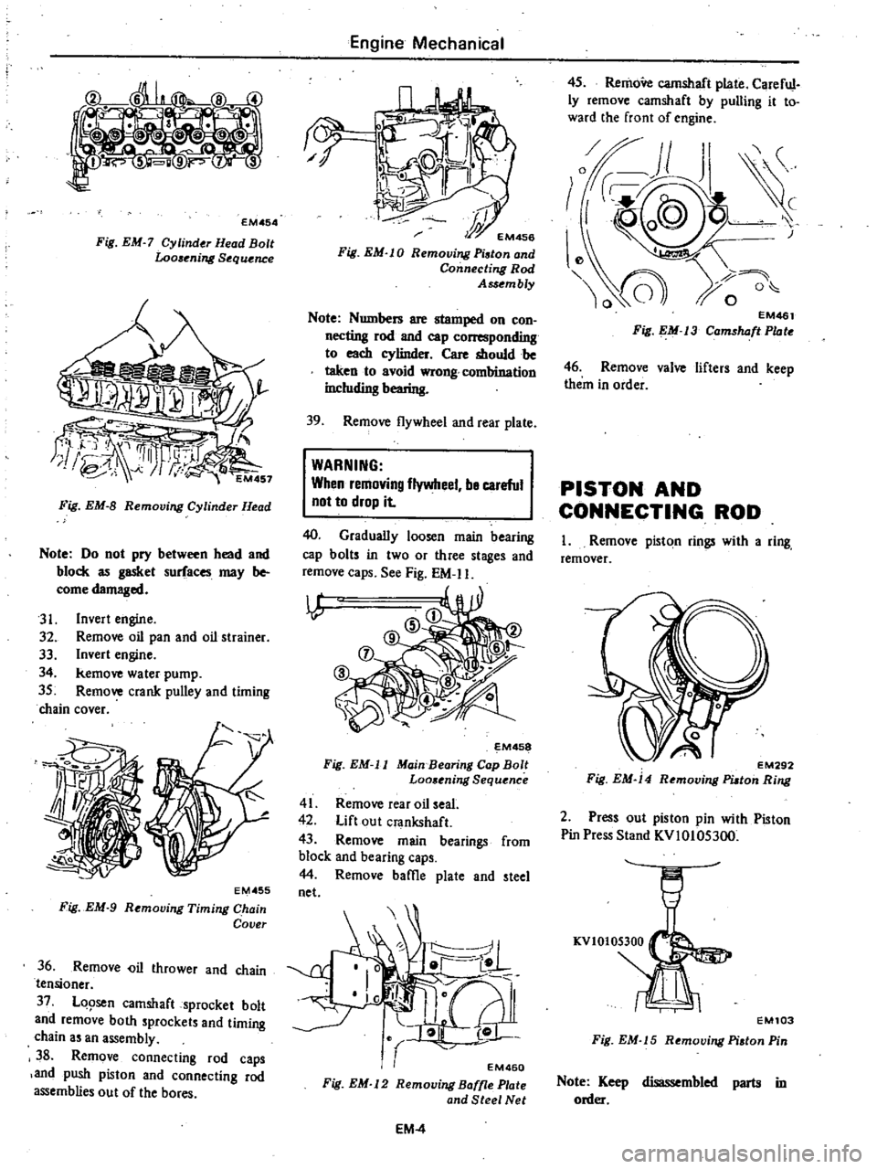
EMA
54
Fig
EM
7
Cylinder
Head
Bolt
Looaening
S
quence
Fig
EM
8
Removing
Cylinder
Ht
ad
Note
Do
not
pry
between
head
and
block
as
gasket
surfaces
may
be
come
damaged
31
Invert
engine
32
Remove
oil
pan
and
oil
strainer
33
Invert
engine
34
kemove
water
pump
35
Remove
crank
pulley
and
timing
chain
cover
EMA
55
Fig
EM
9
Removing
Timing
Chain
Cover
36
Remove
i1
thrower
and
chain
tensioner
37
LQ9sen
camshaft
sprocket
bolt
and
remove
both
procket
and
timing
chain
an
assembly
3
Remove
connecting
rod
caps
and
push
piston
and
connecting
rod
assemblies
out
of
the
bores
Engine
Mechanical
hi
r
EM456
Fig
EM
l
0
Remooing
Piston
and
Connecling
Rod
Assembly
Note
Numbers
are
stamped
on
con
necting
rod
and
cap
rllnding
to
each
cylinder
Care
should
be
taken
to
avoid
wrong
comhination
including
bearing
39
Remove
flywheel
and
rear
plate
WARNING
When
remnving
flywheel
be
careful
not
to
drop
it
40
Gradually
loosen
main
bearing
cap
bolt
in
two
or
three
stages
and
remove
caps
See
Fig
EM
II
I
l
P
@
D
M458
Fig
EM
ll
Main
Bearing
Cap
Bolt
Loo
ning
Sequ
nce
41
Remove
rear
oil
seal
42
Lift
out
crankshaft
43
Remove
main
bearings
from
block
and
bearing
caps
44
Remove
baffie
plate
and
tee
net
EM460
Fig
EM
l2
Remooing
Baffle
Plate
and
Steel
Net
EM
4
45
RemoVe
camshaft
plate
Careful
ly
remove
camshaft
by
pulling
it
to
ward
the
front
of
engine
EM461
Fig
EM
j3
Camshaft
Plate
46
Remove
valve
lifter
and
keep
them
in
order
PISTON
AND
CONNECTING
ROD
I
Remove
piston
rings
with
a
ring
remover
EM292
Fig
EM
14
Remooing
PUton
Ring
2
Press
out
piston
pin
with
Piston
Pin
Press
Stand
KVIOIOS300
EM103
Fig
EM
15
R
moving
Piston
Pin
Note
Keep
disassembled
parts
in
order
Page 73 of 548

DATSUN
210
Model
8310
Series
SECTIONEL
ENGINE
LUBRICATION
SYSTEM
CONTENTS
ENGINE
LUBRICATION
SYSTEM
LUBRICATION
CIRCUIT
01
L
PUMP
OIL
PRESSURE
REGULATOR
VALVE
OIL
PRESSURE
RELIEF
VALVE
OIL
FILTER
OIL
PRESSURE
WARNING
SWITCH
EL
2
EL
2
EL
3
EL
4
EL
4
EL
4
EL
4
SERVICE
DATA
AND
SPECIFICATIONS
TROUBLE
DIAGNOSES
AND
CORRECTIONS
SPECIAL
SERVICE
TOOL
EL
5
EL
5
EL
6
Page 76 of 548
Not
Pump
rotors
and
body
are
not
serv
iced
separatdy
If
pump
rotors
or
body
are
damaged
or
worn
replace
ment
of
the
entire
oil
pump
assembly
isnecessary
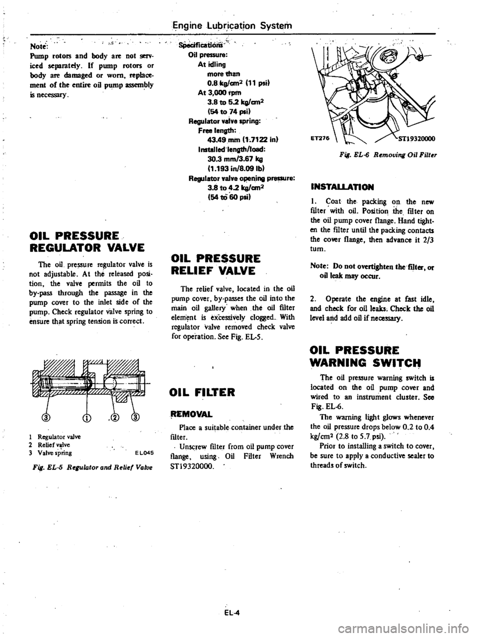
OIL
PRESSURE
REGULATOR
VALVE
The
oil
pressure
regulator
valve
is
not
adjustable
At
the
released
posi
tion
the
valve
permits
the
oil
to
by
pass
through
the
passage
in
the
pump
cover
to
the
inlet
side
of
the
pump
Check
regulator
valve
spring
to
ensure
that
spring
tension
is
correct
no
1
Regulator
valve
2
Relief
valve
3
Valve
spring
E
L045
Fig
EL
5
Regulator
and
Reli
Vatv
Engine
Lubrication
System
8Peciflcatlons
Oil
pressure
At
idling
more
than
O
Blrg
an2
11
psi
At
3
000
rpm
3
B
to
5
2lrg
an2
54
to
74
psi
Regulator
ai
spring
Free
length
43
49
rom
1
7122
in
InstoJlod
l
ngth
load
30
3
mm
3
67
kg
1
193
inJB
09lbl
Regulator
val
o
ning
pressur
3
8
to
4
2
lrg
an2
54
1060
psi
OIL
PRESSURE
RELIEF
VALVE
The
relief
valve
located
in
the
oil
pump
cover
by
passes
the
oil
into
the
main
oil
gallery
when
the
oil
filter
elem
nt
is
exCessively
clogged
With
regula
tor
valve
removed
check
valve
for
operation
See
Fig
EL
5
OIL
FILTER
tEMOVAL
Place
a
suitable
container
under
the
f1lter
Unscrew
f1lter
from
oil
pump
cover
flange
using
Oil
Filter
Wrench
STl9320000
EL
4
Fig
EL
6
Removing
Oil
Filter
INSTALLAnON
I
Coat
the
packing
on
the
new
f1lter
with
oil
Position
the
f1lter
on
the
oil
pump
cover
flange
Hand
tight
en
the
f11ter
until
the
packing
contacts
the
cover
flange
then
advance
it
2
3
tum
Note
Do
not
overtighten
the
fiIter
or
oil
leak
may
occur
2
Operate
the
engine
at
fast
idle
and
check
for
oil
leaks
Check
the
oil
level
and
add
oil
if
necessary
OIL
PRESSURE
WARNING
SWITCIt
The
oil
pressure
warning
switch
is
located
on
the
oil
pump
cover
and
wired
to
an
instrument
cluster
See
Fig
EL
6
The
warning
light
glows
whenever
the
oil
pressure
drops
below
0
2
to
0
4
kg
cm1
2
8
to
5
7
psi
Prior
to
installing
a
switch
to
cover
I
be
sure
to
apply
a
conductive
sealer
to
threads
of
switch
Page 150 of 548
INSPECTION
Entire
system
U
S
A
MIT
models
except
FU
mo
el
1
Ensure
that
wiring
connectors
are
tight
in
pla
ce
2
Ensure
that
vacuum
hoses
are
properly
cof
1o
c
ed
to
their
positions
3
Ensure
that
distributor
vacuum
controller
properly
functions
4
Set
timing
light
and
start
engine
S
While
engine
cooling
water
tem
pefature
is
below
SOOC
I220F
check
function
of
system
as
follows
WARNING
To
protect
against
accidental
for
ward
surge
engage
parking
brake
firmly
while
above
check
is
being
made
I
Run
engine
and
keep
it
at
ap
proximately
1
600
rpm
2
Disengage
clutch
Shift
gears
in
top
3rd
then
neutral
positions
Read
spark
timing
in
respective
shift
posi
tions
The
system
is
properly
functioning
if
spark
timir
g
does
not
change
If
t
changes
check
thefmal
vacuum
valve
3
port
type
Note
Ensure
that
thermal
vacuum
wIve
is
closed
when
cooling
water
i
below
5
to
lSoC
41
to
640F
or
above
SO
to
630C
122
to
14S0F
I
6
After
the
engine
has
been
warmed
up
sufficiently
check
the
function
of
the
system
again
in
the
I
Same
manner
The
system
is
properly
functioning
if
spark
iimin
advances
in
top
posi
tion
If
not
check
thefmal
vacuum
valve
control
circuit
or
vaeu
um
switching
valve
Entire
system
FU
model
and
Canada
MIl
models
I
Ensure
that
wiri
lg
connectors
are
tight
in
place
Emission
Control
System
2
Ensure
that
vacuum
hoses
are
properly
connected
to
their
positions
3
Ensure
that
distributor
vacuum
controller
properly
fu
ctions
4
Set
timing
light
WARNING
To
protect
against
accidental
for
ward
surge
engage
parking
brake
firmly
while
above
check
is
being
made
5
Run
engine
and
keep
it
at
ap
proximately
1
600
1
m
6
Disengage
clutch
Shift
gears
in
4th
5th
ihen
neutral
positions
Read
spark
timing
in
respective
shift
posi
tions
The
system
is
properly
functioning
if
spark
timing
advances
in
top
gear
position
If
spark
timing
does
not
vary
at
all
in
tests
des
rilied
in
step
6
above
check
control
circuit
or
vacuum
switching
valve
Entire
system
California
AIT
models
I
Ensure
th
t
wiring
connectors
are
tight
in
place
2
Ensure
that
vacuum
hoses
are
properly
coIDwcted
to
thejr
positions
3
Ensure
that
distributor
vacuum
controller
function
s
properly
4
Set
timing
light
and
staft
engine
S
While
engine
cooling
water
tem
perature
is
below
SOOC
1220F
check
the
function
of
the
system
as
follows
WARNING
To
protect
againSt
accidental
for
ward
surge
engage
parking
brake
firmly
while
above
check
is
being
made
I
Run
engine
and
keep
it
at
ap
proximately
1
600
rpm
at
P
range
2
Make
a
short
circuit
between
the
specified
two
terminals
at
function
te
t
connector
EC31
The
entire
system
except
for
the
top
switch
is
properly
functioning
if
spark
timing
does
not
change
If
it
changes
check
the
thermal
vacuum
valve
3
pori
type
CAUTION
Pay
attention
not
to
make
a
short
circuit
between
other
terminals
than
the
specified
terminals
or
electrical
system
of
car
will
get
damaged
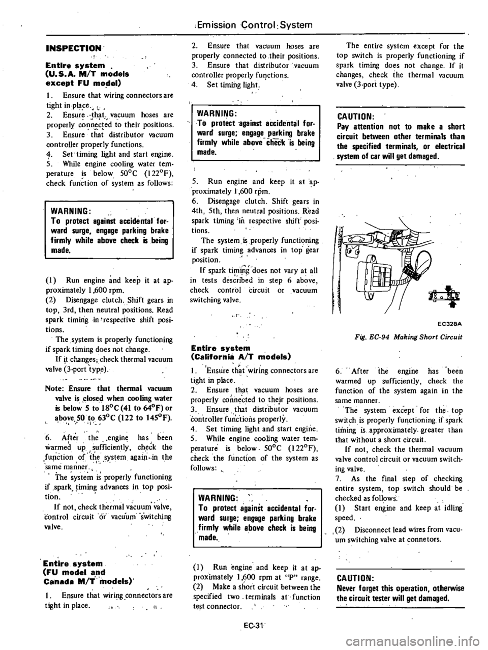
4
EC328A
Fig
EC
94
Making
Short
Circuit
6
After
ihe
engine
has
been
warmed
up
sufficiently
check
the
function
of
the
system
again
in
the
same
manner
The
system
except
for
the
top
switch
is
properly
fU
lctioning
if
spark
timing
is
approximately
greater
than
that
without
a
short
circuit
If
not
check
the
thermal
vacuum
valve
control
circuit
or
vacuum
switch
ing
valve
7
As
the
final
step
of
checking
entire
system
top
switch
should
be
checked
as
follows
1
Start
engine
and
keep
at
idling
speed
2
Disconnect
lead
wires
from
vacu
um
switching
valve
at
connetors
CAUTION
Never
forget
this
operation
otherwise
the
circuit
tester
will
get
damaged
Page 160 of 548
WARNING
Never
touch
positive
and
negative
terminals
at
the
same
time
with
are
hands
Th
l
Il
d
result
in
injury
CHECKING
ELECTROLYTE
LEVEL
Remove
six
vent
plugs
and
check
for
electrolyte
level
in
each
cell
If
necessary
pour
distilled
water
CHECKING
SPECIFIC
GRAVITY
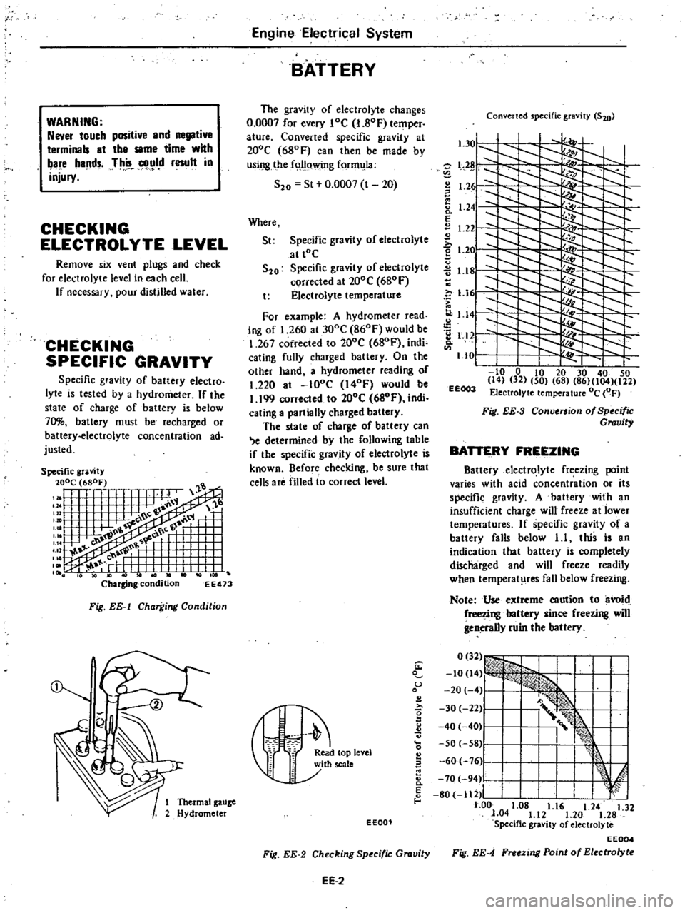
Specific
gravity
of
battery
electro
lyte
is
tested
by
a
hydrometer
If
the
state
of
charge
of
battery
is
below
70
battery
must
be
recharged
or
battery
electrolyte
concentration
ad
justed
EE473
Fig
EE
l
Charging
Condition
Engine
Electrical
System
BATTERY
The
gravity
of
electrolyte
changes
0
0007
for
every
loe
I
80F
temper
ature
Converted
specific
gravity
at
200e
680F
can
then
be
made
by
using
the
following
form
la
S20
St
0
0007
t
20
Where
St
Specific
gravity
of
electrolyte
at
tOe
S20
Specific
gravity
of
electrolyte
corrected
al
200e
680
F
t
Electrolyte
temperature
For
example
A
hydrometer
read
ing
of
1
260
at
300e
860F
would
be
1
267
corrected
to
200e
680F
indi
cating
fully
charged
battery
On
the
olher
hand
a
hydrometer
reading
of
1
220
at
lOoe
I40F
would
be
I
199
corrected
to
200e
680F
indi
cating
a
partially
charged
battery
The
state
of
charge
of
battery
can
e
determined
by
the
following
table
if
the
specific
gravity
of
electrolyte
is
known
Before
checking
be
sure
that
cells
are
filled
to
correct
level
Converted
specific
gravity
S20
l
301
l
Z
L2
I
1
2
I
Ii
8
1
24
E
1
22
2
t
2e
u
1
18
c
i
1
161
1
141
2
1
12
Q
1
10
I
to
0
to
20
30
40
50
14
32
50
68
86
104
122
EEOO3
Electrolyte
temperature
Oc
OF
Fig
EE
3
Conversion
of
Specific
Gravity
BATTERY
FREEZING
Battery
electrolyte
freezing
point
varies
with
acid
concentration
or
its
specific
gravity
A
battery
with
an
insufficient
charge
will
freeze
al
lower
temperatures
If
specific
gravity
of
a
battery
falls
below
1
I
this
is
an
indication
that
battery
is
completely
discharged
and
will
freeze
readily
when
temperat
res
fall
below
freezing
Note
Use
extreme
caution
to
avoid
freezing
battery
since
freezing
will
generally
ruin
the
battery
1
u
B
I
r
eleYel
60
76
Ji
I
k
E
I
I
d
8
70
94
80
112
I
I
f
1
Thermal
gauze
1
00
1
08
1
16
1
24
1
32
2
Hydrometer
1
04
1
12
1
20
1
28
EE001
Specific
gravity
of
electrolyte
EE004
Fig
EE
2
Checking
Specific
Gravity
Fig
EE
4
Freezing
Point
of
Electrolyte
EE
2