air filter DATSUN 210 1979 Owner's Manual
[x] Cancel search | Manufacturer: DATSUN, Model Year: 1979, Model line: 210, Model: DATSUN 210 1979Pages: 548, PDF Size: 28.66 MB
Page 125 of 548
Emission
Control
System
CRANKCASE
EMISSION
CONTROL
SYSTEM
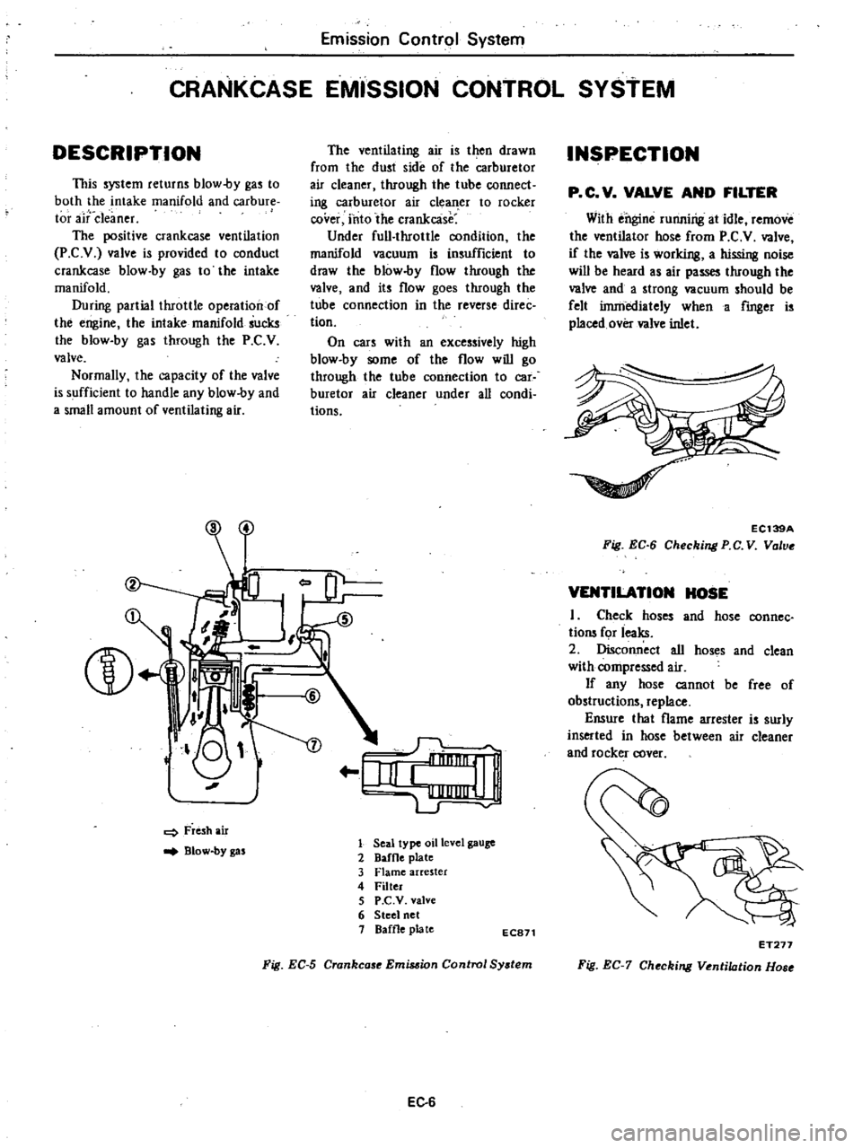
DESCRIPTION
This
system
returns
blow
by
gas
to
both
the
intake
manifold
and
carbure
tor
aitdeaner
The
positive
crankcase
ventilation
P
C
v
valve
is
provided
to
conduct
crankcase
blow
by
gas
to
the
intake
manifold
During
partial
throttle
operation
of
the
engine
the
intake
manifold
sucks
the
blow
by
gas
through
the
P
C
V
valve
Normally
the
capacity
of
the
valve
is
sufficient
to
handle
any
blow
by
and
a
small
amount
of
ventilating
air
L
J
J
o
I
Fresh
air
Blow
by
gas
The
ventilating
air
is
then
drawn
from
the
dust
side
of
the
carburetor
air
cleaner
through
the
tube
connect
ing
carburetor
air
cle
er
to
rocker
cover
into
the
crankcase
Under
full
throttle
condition
the
manifold
vacuum
is
insufficient
to
draw
the
blow
by
flow
through
the
valve
and
its
flow
goes
through
the
tube
connection
in
the
reverse
direc
tion
On
cars
with
an
excessively
high
blow
by
some
of
the
flow
will
go
through
the
tube
connection
to
car
buretor
air
cleaner
under
all
condi
tions
r
IiI
e
1
LJ
1
Seal
type
oil
level
gauge
2
DafOe
plate
3
Flame
arrester
4
Filter
5
P
C
V
valve
6
Steel
net
1
Baffle
plate
EC871
Fig
EC
5
Crankcase
Emis
ion
Control
Sy
tem
EC
6
INSPECTION
p
C
V
VALVE
AND
FILTER
With
ei
gine
runnirig
at
idle
remove
the
ventilator
hose
from
P
C
V
valve
if
the
valve
is
working
a
hissing
noise
wiD
be
heard
as
air
passes
through
the
valve
and
a
strong
vacuum
should
be
felt
irnniediately
when
a
fmger
is
placed
over
valve
inlet
EC139A
Fig
EC
6
Checking
PC
V
Vo
ve
VENTILATION
HOSE
I
Check
hoses
and
hose
connec
tions
for
ieaks
2
oisconn
ct
all
hoses
and
clean
with
compressed
air
If
any
hose
cannot
be
free
of
obstructions
replace
Ensure
that
flame
arrester
is
surly
inserted
in
hose
between
air
cleaner
and
rocker
rover
ET277
Fig
EC
7
Checking
Ventilation
Hose
Page 131 of 548

following
functions
without
affecting
the
effectiveness
of
the
exhaust
emis
sion
control
system
Minimizes
exhaust
gas
tempera
ture
rise
2
Minimizes
horsepower
losses
reo
sulting
from
air
injection
into
the
exhaust
system
3
Protects
pump
from
excessive
back
pressure
To
carburetor
air
cleaner
Secondary
ir
Not
actuated
To
carburetor
air
cleaner
J
l
Secondary
sir
Actuated
EC294
Fig
EC
18
Air
Pump
Relief
Valve
c
A
C
valve
Californiamodels
The
C
A
C
valve
controls
the
quantity
of
secondary
air
fed
from
the
air
pump
according
to
the
load
condi
tion
and
it
discharges
the
secondary
air
into
the
atmosphere
to
prevent
overheating
of
the
catalytic
converter
This
valve
is
operated
by
intake
manifold
vacuum
and
air
pump
dis
charge
pressure
When
intake
manifold
vacuum
is
small
or
in
the
high
load
range
the
No
2
valve
opens
when
it
is
great
or
in
the
low
load
range
the
No
I
valve
opens
If
air
pump
discharge
pressure
is
large
or
the
engine
is
running
at
a
high
speed
the
No
3
valve
opens
admitting
the
air
pump
discharge
pressure
to
the
No
2
dia
phragm
chamber
of
the
C
A
C
valve
mission
Control
System
and
opening
ihe
No
i
valve
At
this
point
the
No
2
valve
serves
as
a
relief
valve
F
111
air
pump
No
3
valve
EC787
Fig
EC
19
C
A
C
Valve
I
Engine
in
low
speed
and
light
load
When
the
engine
is
operating
under
these
conditions
intake
vacuum
is
high
The
No
2
valve
unitized
with
the
No
I
diaphragm
is
lifted
by
the
intake
manifold
vacuum
pushing
up
the
No
I
valve
These
valves
will
then
stop
at
a
position
where
a
balanced
condition
exists
between
air
pump
discharge
pressure
an
d
spring
tension
acting
on
the
No
I
and
No
2
valves
The
No
2
jiaphragm
however
does
not
move
due
to
low
engine
speed
low
air
pump
discharge
pressure
and
spring
tension
acting
on
the
No
3
valve
For
this
reason
these
valves
are
brought
to
a
balanced
condition
To
intake
manifold
t
i
l
3
Spring
4
ValveNo
3
5
Di
phragm
No
I
I
@
6
Spring
7
Valve
No
1
8
Valve
No
2
EC683
Fig
EC
20
Operation
of
C
A
C
Valve
1
2
Engine
in
low
speed
and
heavy
load
EC12
Wheo
the
engine
is
operating
under
these
cooditions
intake
manifold
vacuum
is
low
and
all
valves
are
balanced
t
To
intake
manUol
U
E
ii
ji
j
Ii
5
LL
jj
Ii
JI
l
Jij
ulJC
1t
To
atmosphere
EC685
Fig
EC
21
Operation
of
C
A
C
Valve
2
3
Engine
in
high
speed
and
middle
load
When
the
engine
is
operating
under
these
conditions
intake
manifold
vacuum
lies
midway
between
1
and
2
above
The
No
3
valve
moves
to
the
left
because
of
high
air
pump
discharge
pressure
To
intake
manifold
t
L
J
f
E
bt
I
5
tfi
11
I
LJr
To
tmg
J
j
1
EC
4
Fig
EC
22
Operation
of
C
A
C
Volve
3
REMOVAL
AND
INSTALLATION
Air
pump
air
cleaner
Loosen
nuts
securing
air
pump
air
cleaner
to
bracket
then
detach
air
cleaner
from
bracket
Air
cleaner
filter
and
air
cleaner
lower
body
are
built
into
a
unit
construction
Replace
air
cleaner
filter
and
lower
body
as
an
assembly
Page 132 of 548

EC149A
Fig
EC
23
Removing
Air
Cleaner
Filter
Air
pump
1
Remove
air
hoses
from
air
pump
2
Remove
air
pump
pulley
3
Loosen
air
pump
adjusting
bar
mounting
bolts
and
air
pump
mount
ing
bolts
then
remove
air
pump
drive
belt
4
Air
pump
assembly
can
be
taken
out
from
bracket
5
Installation
is
in
the
reverse
se
quence
of
removal
Fig
EC
24
Removing
Air
Pump
Check
valve
1
Disconnect
air
hose
from
check
valve
2
Remove
check
valve
from
engine
cylinder
head
3
Installation
is
in
the
reverse
se
fluence
of
removal
Emission
Control
System
EC151A
Fig
EC
25
Removing
Check
Valve
A
B
valve
A
B
valve
is
located
at
the
rear
side
of
air
cleaner
Remove
air
hoses
and
vacuum
tube
A
B
valve
can
then
be
taken
out
EC152A
Fig
EC
26
Removing
A
B
Valve
Air
pump
relief
valve
Non
California
models
I
Loosen
clamp
of
air
hose
and
disconnect
air
hose
from
relief
valve
EC
13
2
Remove
screws
securing
relief
valve
to
air
cleaner
Relief
valve
can
then
be
taken
out
easily
3
Installation
is
in
the
reverse
se
quence
of
removal
EC153A
Fig
EC
27
Removing
Air
Pump
Relief
Valve
C
A
C
valve
California
models
C
A
C
valve
is
located
beneath
con
trol
device
bracket
Remove
clamps
and
disconnect
air
hoses
and
vacuum
tube
2
Remove
screws
securing
C
A
C
valve
Air
control
valve
can
then
be
taken
out
easily
3
Installation
is
in
the
reverse
se
quence
of
removal
EC154A
Fig
EC
28
Removing
C
A
C
Volvo
Page 137 of 548
Note
When
tho
vaCUUm
hose
is
dis
connected
plug
it
up
or
engine
will
stumble
EC
47A
FiJ
Fig
EC
49
Disconnecting
Vacuum
Hose
from
C
A
C
Valve
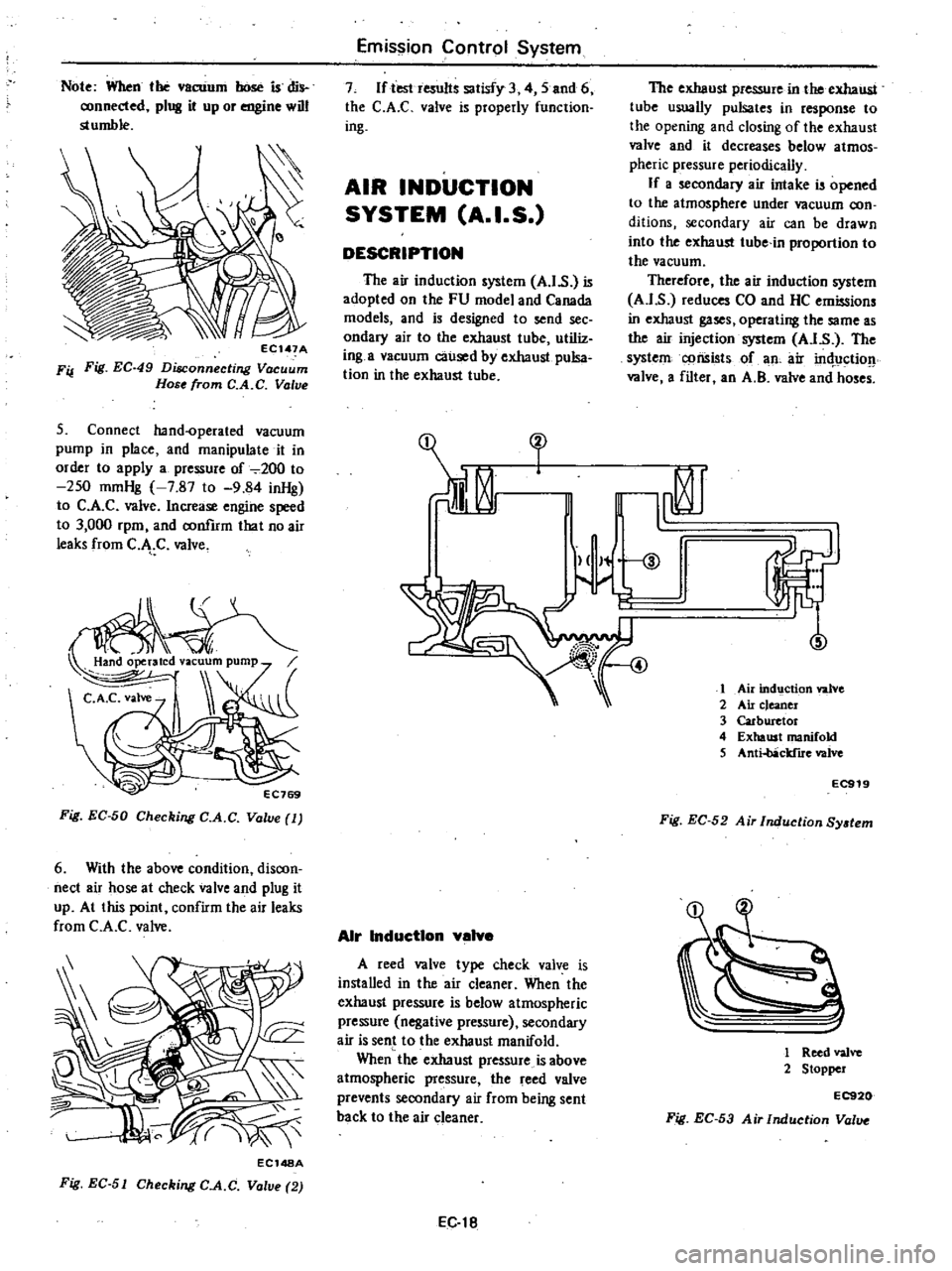
5
Connect
hand
operated
vacuum
pump
in
place
and
manipulate
it
in
order
to
apply
a
pressure
of
2oo
to
250
mmHg
7
87
to
9
84
inHg
to
C
A
C
valve
Increase
engine
speed
to
3
000
rpm
and
confIrm
that
no
air
leaks
from
C
J
C
valve
Fig
EC
50
Checking
C
A
C
Valve
1
6
With
the
above
condition
discon
nect
air
hose
at
check
valve
and
plug
it
up
At
this
point
confirm
the
air
leaks
from
C
A
C
valve
ECl48A
Fig
EC
51
Checking
C
A
C
Volve
2
Emission
Control
System
7
If
teshesults
satisfy
3
4
5
and
6
the
C
A
C
valve
is
properly
function
ing
AIR
INDUCTION
SYSTEM
A
I
S
DESCRIPTION
The
air
induction
system
A
1
s
is
adopted
on
the
FU
model
and
Canada
models
and
is
designed
to
send
see
ondary
air
to
the
exhaust
tube
utiliz
ing
a
vacuum
caused
by
exhaust
pulsa
tion
in
the
exhaust
tube
Air
inductIon
valve
A
reed
valve
type
check
valve
is
installed
in
the
air
cleaner
When
the
exhaust
pressure
is
below
atmospheric
pressure
negative
pressure
secondary
air
is
sent
to
the
exhaust
manifold
When
the
exhaust
pressure
is
above
atmospheric
pressure
the
reed
valve
prevents
secondary
air
from
being
sent
back
to
the
air
cleaner
EC
t8
The
exhaust
pressure
in
the
exhaust
tube
usually
pulsates
in
response
to
the
opening
and
closing
of
the
exhaust
valve
and
it
decreases
below
atmos
pheric
pressure
periodically
If
a
secondary
air
intake
is
opened
to
the
atmosphere
under
vacuum
con
ditions
secondary
air
can
be
drawn
into
the
exhaust
tube
in
proportion
to
the
vacuum
Therefore
the
air
induction
system
A
I
s
reduces
CO
and
HC
emissions
in
exhaust
gases
operatiug
the
same
as
the
air
injection
system
A
I
s
The
system
cpnsistsof
an
air
in
tJctio
valve
a
filter
an
A
B
valve
and
hoses
fl
V
t
5
1
Air
ind9ction
valve
2
Air
c
eancr
3
Carburetor
4
Exhaust
manifold
5
Anti
obRcldlre
valve
EC919
Fig
EC
52
Ai
Induction
SYltem
1
Reed
valvo
2
Stopper
EC920
Fig
EC
53
Air
Induction
Val
Page 138 of 548

Air
Induction
v
lve
filter
The
air
induction
valve
filter
is
installed
at
the
dust
side
of
the
air
cleaner
It
purifies
secondary
air
to
be
sent
to
the
exhaust
tube
The
fIlter
element
should
be
replaced
periodical
ly
in
accordance
with
the
Maintenance
Schedule
EC921
Fig
EC
54
Air
Induction
Valve
Filter
Antl
beckflre
v
lve
A
B
v
lve
Tltis
valve
is
controlled
by
intake
manifold
vacuum
to
prevent
backfire
in
the
exhaust
system
at
the
initial
period
of
deceleration
At
this
period
the
mixture
in
the
intake
manifold
becomes
too
rich
to
ignite
and
burn
in
the
combustion
chamber
and
burns
easily
in
the
ex
haust
system
with
injected
air
in
the
exhaust
manifold
The
anti
backfire
valve
provides
air
to
the
intake
manifold
to
make
the
air
fuel
mixture
leaner
and
prevents
backfire
If
the
valve
does
not
work
properly
unburned
ntixture
will
be
emitted
from
the
combustion
chambers
and
burns
with
the
aid
of
high
temperature
and
injected
air
which
causes
backfrre
To
intake
manifold
vacuum
To
intake
manifold
From
air
cleaner
EC069
Fig
EC
55
Anti
backfire
Value
Emission
Control
System
Air
Induction
Into
exhaust
port
The
secondary
air
fed
from
the
air
induction
valve
goes
through
the
check
valve
to
the
air
gallery
in
the
cylinder
head
It
is
then
distributed
to
each
exhaust
port
and
injected
near
the
exhaust
valve
I
Air
gallery
2
Exhaust
port
3
Exhaust
manifold
EC316
Fig
EC
56
Sectional
View
of
Exhaust
Port
REMOVAL
AND
INSTALLATION
Air
Induction
valve
and
filter
Remove
the
screws
securing
the
valve
and
filter
to
the
air
cleaner
body
The
air
induction
valve
and
valve
filter
can
then
be
taken
out
easily
Installa
tion
is
in
the
reverse
sequence
of
removal
EC922
Fig
EC
57
Removing
Air
Induction
Valve
and
Filter
EC
19
Air
Induction
pipe
Loosen
out
a
nut
securing
the
pipe
to
the
engine
cylinder
head
At
the
same
time
remove
the
screws
securing
the
bracket
and
rubber
hose
clamp
The
air
induction
pipe
can
then
be
taken
out
Installation
is
in
the
reverse
sequence
of
removal
Fig
EC
58
A
B
valve
The
A
B
valve
is
located
at
the
rear
side
of
the
air
cleaner
Remove
the
air
hoses
and
vacuum
tube
The
A
B
valve
can
then
be
taken
out
Installation
is
in
the
reverse
se
quence
of
removal
EC152A
Fig
EC
59
Removing
A
B
Valve
INSPECTION
Preliminary
Inspection
Check
hose
for
looseness
flatting
damage
or
faulty
connections
and
each
part
for
proper
installation
If
necessary
replace
Air
Induction
valve
and
filter
I
Disconnect
air
induction
hose
at
air
induction
pipe
side
Suck
or
blow
hose
to
make
sure
that
air
flows
only
on
the
air
induction
pipe
side
Page 139 of 548

EC924
Fig
EC
60
Checking
Air
Induction
Valve
2
Check
air
induction
valve
reed
valve
for
binding
or
damage
At
the
same
time
check
filter
for
damage
or
plugging
If
necessary
replace
Filter
should
be
replaced
periodically
in
ac
cordance
with
Maintenance
Schedule
Emission
Control
System
1
Air
induction
valve
filter
2
Air
induction
valve
EC925
Fig
EC
6I
Checking
Air
Induction
Valve
and
Filter
Anti
backfire
valve
A
B
alve
I
Warm
up
engine
thoroughly
2
Disconnect
hose
from
air
cleaner
EC
20
and
place
aflriger
near
tneoutlet
3
Run
engine
at
about
3
000
rpm
under
no
load
then
quickly
return
it
to
idling
If
you
feel
a
pull
or
suction
force
on
your
finger
the
anti
J
ackfire
valve
is
functioning
normally
If
no
suction
is
felt
replace
the
anti
backfire
valve
eC76S
Fig
EC
62
Checking
Anti
bock
ire
Valve
Page 155 of 548

OPERATION
Fuel
vapors
from
the
sealed
fuel
tank
are
led
into
the
carbon
canister
The
canister
is
filled
with
activated
charcoals
to
absorb
the
fuel
vapors
when
the
engine
is
at
rest
or
at
idling
t
Fuel
tank
2
Fuel
filler
cap
with
vacuum
re1ief
va1ve
3
Fuel
check
vslve
4
Vapor
t
line
5
Vacuum
signal
line
6
Canister
purge
line
Emission
Control
System
As
the
throttle
Valve
opens
and
car
speed
increases
vacuum
pressure
in
the
vacuum
signajline
forces
the
purge
control
valve
to
open
and
admits
an
orifice
to
intake
manifold
and
fuel
vapor
is
then
drawn
into
the
intake
manifold
through
the
canister
purge
line
Fuel
vapor
7
Throttle
valve
IZ
Filter
8
Engine
13
Purge
control
valve
9
Carbon
cani5t
14
DiaphraP
spring
10
Activated
carbon
IS
Diaphngm
II
Screen
16
Fixed
orifice
EC785
Fig
EC
JOS
Evaporative
Emiuion
Control
System
Fuel
vapor
flow
when
ngine
is
at
rest
or
running
REMOVAL
AND
INSTALLAtiON
CARBON
CANISTER
FILTER
Check
for
a
contantinated
element
Elemenl
can
be
removed
at
the
bottom
of
canister
installed
on
car
body
EF201
Fig
EC
I06
Replacing
Carbon
Canilttr
Filter
CHECK
VALVE
The
check
valve
is
located
behind
the
luggage
compartment
board
on
the
fuel
tank
Remove
the
luggage
compartment
board
and
disconnect
the
vapor
tube
The
check
valve
can
then
be
taken
out
EC315A
Fig
EC
I07
Removing
Check
Volve
EC
36
INSPECTION
FUEL
TANK
AND
VAPOR
VENT
LINE
1
Check
all
hoses
and
fuel
tank
filler
cap
2
Disconnect
the
vapor
vent
line
connecting
carbon
canister
to
check
valve
3
Connect
a
3
w
y
connector
a
manometer
and
a
cock
or
an
equi
valent
3
way
charge
cock
to
the
end
of
the
vent
line
EC183A
Fig
EC
IOB
Vent
Line
4
Supply
fresh
air
into
the
vapor
vent
line
through
the
cock
little
by
little
until
pressure
becomes
368
mmHZO
14
5
inHZO
S
Shut
the
cock
completely
and
leave
it
unattended
6
After
2
5
minutes
measure
the
height
of
the
liquid
in
the
manometer
7
Variation
in
height
should
remain
with
25
mmHZO
0
98
inH20
8
When
filler
cap
does
not
close
completely
the
height
should
drop
to
zero
in
a
short
time
9
If
the
height
does
not
drop
to
zero
in
a
short
time
when
ruler
cap
is
d
it
is
the
cause
of
a
stuffy
hose
Note
In
case
the
vent
line
is
stuffy
the
breathing
in
fuel
tank
is
not
thoroughly
IIIIIde
thus
causing
in
sufficient
delivery
of
feul
to
engine
or
vapor
lock
It
must
therefore
be
repaired
or
replaced
Page 357 of 548
REMOVAL
I
Disconnect
wiring
to
brake
fluid
level
gauge
2
Disconnect
front
and
rear
brake
tubes
from
master
cylinder
CAUTION
When
removing
brake
tubes
use
suitable
tube
wrench
Never
use
open
end
or
edjustllble
wrench
Note
When
disconnecting
brake
tubes
be
sure
to
use
a
container
to
receive
draining
brake
fluid
Use
of
raga
is
also
suggested
to
keep
adjacent
perts
and
area
clean
3
Remove
master
cylinder
securing
nut
Master
cylinder
can
then
be
taken
out
DISASSEMBLY
1
Remove
reservoir
caps
and
filtern
and
drain
out
brake
fluid
2
Pry
off
stopper
ring
using
a
screwdriver
3
Remove
stopper
screw
and
take
out
stopper
primary
piston
assembly
spring
and
secondary
piston
assembly
in
the
order
shown
Note
Discard
caps
if
they
are
reo
moved
from
piston
assemblies
and
use
new
ones
4
Unscrew
pluga
to
gain
access
to
check
valve
for
disassembling
Note
a
Never
detach
reservoir
tanks
If
they
are
removed
for
any
reason
discard
them
and
install
new
ones
b
Do
not
remove
or
disassemble
brake
fluid
level
gauge
INSPECTION
Thoroughly
clean
all
parts
in
a
suitable
solvent
and
check
them
for
wear
or
damage
Replace
any
part
that
is
faulty
Brake
System
CAUTION
Use
brake
fluid
to
clean
Never
use
mineral
oil
I
Check
cylinder
and
pistons
for
evidence
of
abnonnal
wear
or
damage
Replace
if
found
faulty
2
Check
piston
to
cylinder
clear
ance
If
it
exceeds
the
specified
value
replace
either
piston
or
cylinder
Piston
to
cylinder
clearance
less
than
0
15
mm
0
0059
in
3
Check
springs
for
weakness
fatigue
or
damage
Replace
if
neces
sary
4
When
master
cylinder
is
disas
sembled
be
sure
to
discard
caps
and
valves
Replace
any
other
parts
which
show
evidence
of
deformation
wear
or
other
damage
S
Replace
damaged
oil
reservoirs
and
caps
ASSEMBLY
Assemble
master
cylinder
following
the
reverse
procedure
of
disassembly
paying
particular
attention
to
the
fol
lowing
note
Note
a
Replace
gaskets
and
packing
with
new
ones
b
Apply
brake
fluid
or
rubber
grease
to
sliding
contact
surface
of
parts
to
facilitate
assembly
of
master
cylinder
c
The
brake
master
cylinder
is
avail
able
in
both
NABCO
make
and
TOKICO
make
There
is
no
inter
changeability
of
repair
kits
or
com
ponent
parts
between
NABCO
and
TOKlCO
makes
When
replacing
the
repair
kit
or
component
parts
ascertain
the
brand
of
the
brake
master
cylinder
body
Be
sure
to
use
parts
of
the
same
make
as
the
fonner
ones
INSTALLATION
Install
master
cylinder
following
the
reverse
procedure
of
removal
After
installation
bleed
brake
system
BR
5
CAUTION
When
installing
Flare
Nut
6694310000
brake
tubes
use
Torque
Wrench
CiJ
Tightening
torque
Brake
master
cylinder
securing
nut
0
8
to
t
1
kg
m
5
8
to
8
0
ft
lb
Brake
tube
flare
nut
1
5
to
1
8
kg
m
11
to
13
ft
b
BRAKE
FLUID
LEVEL
GAUGE
Inspection
I
Disengage
hand
brake
control
lever
2
Raise
cap
and
make
sure
that
hand
brake
warning
lamp
goes
on
when
float
comes
into
contact
with
stopper
BRAKE
LINE
REMOVAL
I
Remove
flare
nuts
on
both
ends
and
remove
retainers
and
clips
CAUTION
When
removing
brake
tubes
and
hoses
use
suitable
tube
wrench
Never
use
open
end
or
adjustable
wrench
2
To
remove
brake
hose
first
re
move
flare
nut
securing
brake
tube
to
brake
hose
and
withdraw
lock
spring
End
of
hose
can
then
be
removed
from
bracket
Next
remuve
brake
hose
Do
not
twist
brake
hose
INSPECTION
Check
brake
lines
tubes
and
hoses
for
evidence
of
cracks
deterioration
or
other
damage
Replace
any
faulty
parts
Page 403 of 548
Engine
Control
Fuel
Exhaust
Systems
REMOVAL
WARNING
When
replacing
fuel
line
parts
be
sure
to
observe
the
following
a
Put
a
CAUTION
INFLAM
MABLE
sign
in
workshop
b
Be
sure
to
furnish
workshop
with
In
asphyxiator
c
Be
sure
to
disconnect
battery
ground
cable
before
conducting
operations
d
Put
drained
fuel
in
an
explosion
proof
container
and
put
on
lid
securely
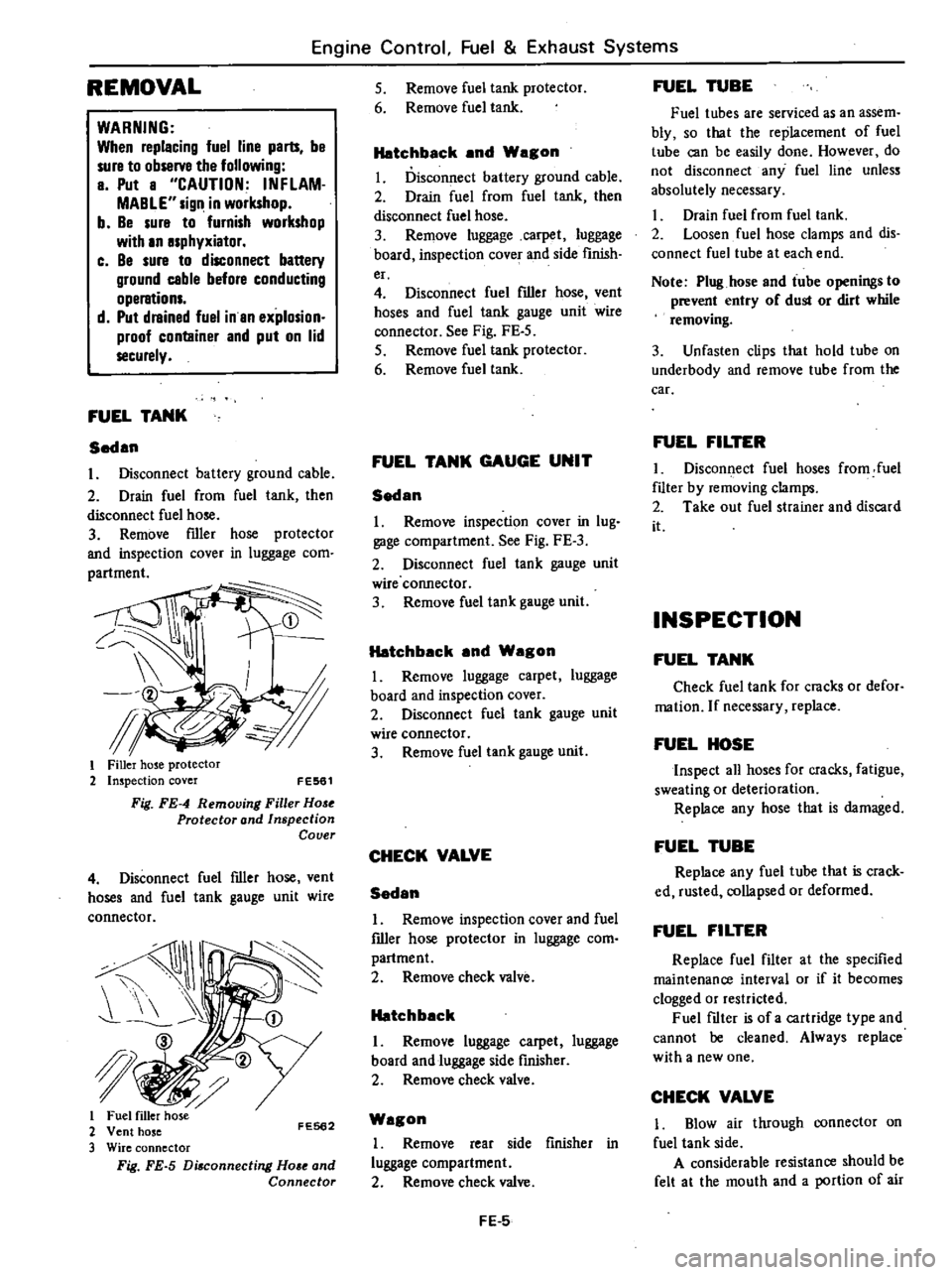
FUEL
TANK
Sedan
I
Disconnect
battery
ground
cable
2
Drain
fuel
from
fuel
tank
then
disconnect
fuel
hose
3
Remove
filler
hose
protector
and
inspection
cover
in
luggage
com
i
tl
f
I
Filler
hose
protector
2
Inspection
cover
FE561
Fig
FE
4
Removing
Filler
Hose
Protector
and
Inspection
Cover
4
Disconnect
fuel
filler
hose
vent
hoses
and
fuel
tank
gauge
unit
wire
connector
I
JI
I
2
FE562
3
Fig
FE
5
Di
connecting
Ho
e
and
Connector
5
Remove
fuel
tank
protector
6
Remove
fuel
tank
Hatchback
and
Wagon
I
Disconnect
battery
ground
cable
2
Drain
fuel
from
fuel
tank
then
disconnect
fuel
hose
3
Remove
luggage
carpet
luggage
board
inspection
covef
and
side
finish
er
4
Disconnect
fuel
filler
hose
vent
hoses
and
fuel
tank
gauge
unit
wire
connector
See
Fig
FE
5
5
Remove
fuel
tank
protector
6
Remove
fuel
tank
FUEL
TANK
GAUGE
UNIT
Sedan
1
Remove
inspection
cover
in
lug
gage
compartment
See
Fig
FE
3
2
Disconnect
fuel
tank
gauge
unit
wire
connector
3
Remove
fuel
tank
gauge
unit
Hatchback
and
Wagon
I
Remove
luggage
carpet
luggage
board
and
inspection
cover
2
Disconnect
fuel
tank
gauge
unit
wire
connector
3
Remove
fuel
tank
gauge
unit
CHECK
VALVE
Sedan
I
Remove
inspection
cover
and
fuel
filler
hose
protector
in
luggage
com
partment
2
Remove
check
valve
Hatchback
I
Remove
luggage
carpet
luggage
board
and
luggage
side
finisher
2
Remove
check
valve
Wagon
I
Remove
rear
side
finisher
in
luggage
compartment
2
Remove
check
valve
FE
5
FUEL
TUBE
Fuel
tubes
are
serviced
as
an
assem
bly
so
that
the
replacement
of
fuel
tube
can
be
easily
done
However
do
not
disconnect
any
fuel
line
unless
absolutely
necessary
Drain
fuel
from
fuel
tank
2
Loosen
fuel
hose
clamps
and
dis
connect
fuel
tube
at
each
end
Note
Plug
hose
and
tube
openings
to
prevent
entry
of
dust
or
dirt
while
removing
3
Unfasten
clips
that
hold
tube
on
underbody
and
remove
tube
from
the
car
FUEL
FILTER
I
Disconnect
fuel
hoses
from
fuel
filter
by
removing
clamps
2
Take
out
fuel
strainer
and
discard
it
INSPECTION
FUEL
TANK
Check
fuel
tank
for
cracks
or
defor
mation
If
necessary
replace
FUEL
HOSE
Inspect
all
hoses
for
cracks
fatigue
sweating
or
deterioration
Replace
any
hose
that
is
damaged
FUEL
TUBE
Replace
any
fuel
tube
that
is
crack
ed
rusted
collapsed
or
deformed
FUEL
FILTER
Replace
fuel
filter
at
the
specified
maintenance
interval
or
if
it
becomes
clogged
or
restricted
Fuel
filter
is
of
a
cartridge
type
and
cannot
be
cleaned
Always
replace
with
a
new
one
CHECK
VALVE
1
Blow
air
through
connector
on
fuel
tank
side
A
considerable
resistance
should
be
felt
at
the
mouth
and
a
portion
of
air
Page 507 of 548
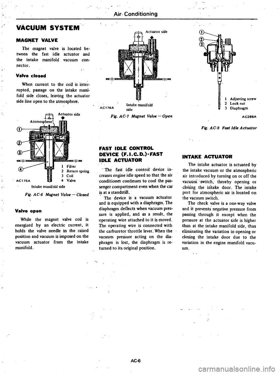
VACUUM
SYSTEM
MAGfilET
VALVE
The
magnet
valve
is
located
be
tween
the
fast
idle
actuator
and
the
intake
manifold
vacuum
con
nector
Valve
cloaed
When
current
to
the
coil
is
inter
rupted
passage
on
the
intake
mani
fold
side
closes
leaving
the
actuator
side
line
open
to
the
atmosphere
Actuator
side
j
I
i
r
1
Filter
2
Return
spring
3
Coil
AC175A
4
Valve
Intake
manifold
side
Fig
AG
6
Magnet
Valve
Glosed
Velve
open
While
the
magnet
valve
coil
is
energized
by
an
electric
current
it
holds
the
valve
needle
in
the
raised
position
and
vacuum
is
imposed
on
the
vacuum
actuator
from
the
intake
manifold
Air
Conditioning
Actuator
side
AC176A
Intake
manifold
side
Fig
AG
7
Magnet
Valve
Open
FAST
IDLE
CONTROL
DEVICE
F
I
C
D
FAST
IDLE
ACTUATOR
The
fast
idle
control
device
in
creases
engine
idle
speed
so
that
the
air
conditioner
continues
to
cool
the
pas
senger
compartment
even
when
the
car
is
at
a
standstill
The
device
is
a
vacuum
actuator
and
is
equipped
with
a
diaphragm
The
diaphragm
deflects
when
vacuum
pres
sure
is
applied
and
as
a
result
the
operating
wire
attached
to
it
is
moved
The
operating
wire
is
connected
with
the
carburetor
throttle
lever
When
the
vacuum
pressure
acting
on
the
dia
phragm
is
lost
the
diaphragm
is
reo
turned
to
its
original
position
AC
6
1
Adjusting
screw
2
Lock
nut
3
Diaphragm
AC266A
Fig
AG
B
FlUI
Idle
Actuator
INTAKE
ACTUATOR
The
intake
actuator
is
actuated
by
the
intake
vacuum
or
the
atmospheric
air
introduced
by
turning
on
or
off
the
vacuum
switch
thereby
opening
or
closing
the
intake
door
The
intake
port
for
atmospheric
air
is
located
on
the
vacuum
switch
The
check
valve
is
a
one
way
valve
and
it
prevents
negative
pressure
from
passing
through
it
except
when
the
pressure
at
the
actuator
side
is
higher
than
at
the
intake
manifold
side
thus
eliminating
the
variation
in
opening
or
closing
the
intake
door
due
to
the
variation
in
the
engine
manifold
vacu
urn