check engine light DATSUN 210 1979 Owner's Manual
[x] Cancel search | Manufacturer: DATSUN, Model Year: 1979, Model line: 210, Model: DATSUN 210 1979Pages: 548, PDF Size: 28.66 MB
Page 175 of 548
Engine
Electrical
System
6
Tighten
through
bolts
rfl
Tightening
torque
Through
bolts
60
to
70
kg
cm
52
to
61
in
lb
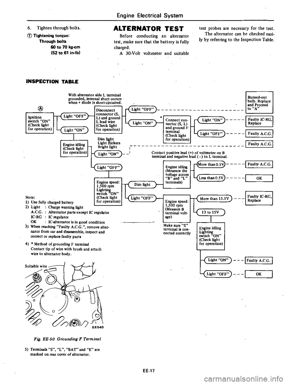
ALTERNATOR
TEST
Before
conducting
an
alternator
test
make
sure
that
the
battery
is
fully
charged
A
30
Volt
voltmeter
and
suitable
INSPECTION
TABLE
With
alternator
aide
L
tenninal
grounded
internal
short
occurs
when
diode
is
short
circuited
@
test
probes
are
necessary
for
the
test
The
alternator
can
be
checked
easi
ly
by
referring
to
the
Inspection
Table
Bumed
out
bulb
Replace
and
Proceed
toUA
Ignition
switch
ON
Check
light
for
operation
Disconnect
Light
OFF
f
Light
OFF
connector
S
L
and
ground
L
lead
wire
Light
ON
Check
light
for
operation
Light
ON
I
Faulty
IC
RG
Replace
Connect
con
nector
S
L
and
ground
F
a1light
Light
OFF
I
FaultyA
C
G
I
Dim
light
for
operation
tf
i
rs
1
I
Faulty
A
C
G
I
Light
ON
I
Contact
positive
lead
of
voltmeter
on
B
lennina
and
negative
lead
to
L
tenninal
Light
ON
1
Engine
idling
Check
light
for
operation
Light
OFF
I
Engine
idling
Measure
the
voltage
across
B
and
L
terminals
Engine
speed
1
500
rpm
Ligh
tin
switch
ON
Check
light
for
operation
r
Dim
light
Light
OFF
Note
1
Use
fully
charged
battery
2
Light
Charge
warning
light
A
C
G
Alternator
parts
except
IC
regu
tor
IC
RG
IC
n
guJator
OK
IC
altemator
is
in
good
condition
3
When
reaching
Faulty
A
C
G
remove
alter
nator
from
car
and
disassemble
inspect
and
correct
or
replace
faulty
parts
Engine
speed
1
500
rpm
Measure
B
terminal
volt
sge
Make
sure
S
terminal
is
con
nected
correctly
4
Method
of
grounding
F
terminal
Contact
tip
of
wire
with
brush
and
attach
wire
to
alternator
body
Suitable
wire
I
Fig
EE
50
Grounding
F
Terminal
5
Terminals
S
L
BA
Tn
and
E
are
marked
on
rear
cover
of
alternator
EEl7
More
thanO
5V
I
Faulty
A
e
G
1
Less
thanO
5V
I
OK
T
Mon
than
15
5V
I
Z
C
RG
I
I3
to
15V
Engine
idling
Lighting
switch
ON
Check
light
for
operation
Light
ON
I
Faulty
A
C
G
I
Light
OFF
I
OK
Page 187 of 548
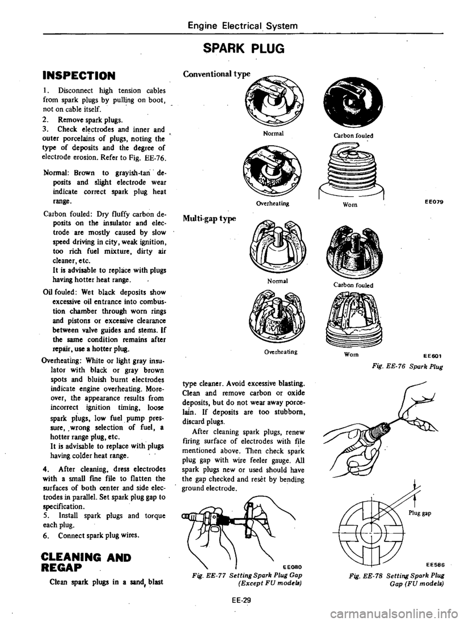
INSPECTION
I
Disconnect
high
tension
cables
from
spark
plugs
by
pulling
on
boot
not
on
cable
itself
2
Remove
spark
plugs
3
Check
electrodes
and
inner
and
outer
porcelains
of
plugs
noting
the
type
of
deposits
and
the
degree
of
electrode
erosion
Refer
to
Fig
EE
76
Normal
Brown
to
grayish
Ian
de
posits
and
slighl
electrode
wear
indicate
correct
spark
plug
heat
range
Carbon
fouled
Dry
fluffy
carbon
de
posits
on
the
insulator
and
elec
trode
are
mostly
caused
by
slow
speed
driving
in
city
weak
ignition
too
rich
fuel
mixture
dirty
air
cleaner
etc
H
is
advisable
to
replace
with
plugs
having
hotter
heat
range
Oil
fouled
Wet
black
deposits
show
excessive
oil
entrance
into
comb
us
tion
chamber
through
worn
rings
and
pistons
or
excessive
clearance
between
valve
guides
and
stems
If
the
same
condition
remains
after
repair
use
a
hotter
plug
Overheating
White
or
light
gray
insu
lator
with
black
or
gray
brown
spots
and
bluish
burnt
electrodes
indicate
engine
overheating
More
over
the
appearance
results
from
incorrect
ignition
timing
loose
spark
plugs
low
fuel
pump
pres
sure
wrong
selection
of
fuel
a
hotter
range
plug
etc
H
is
advisable
to
replace
with
plugs
having
colder
heat
range
4
After
cleaning
dress
electrodes
with
a
smaU
fme
file
to
flatten
the
surfaces
of
both
center
and
side
elec
trodes
in
parallel
Set
spark
plug
gap
to
specification
5
Install
spark
plugs
and
torque
each
plug
6
Connect
spark
plug
wires
CLEANING
AND
REGAP
Clean
spark
plugs
in
a
sand
blast
Engine
Electrical
System
SPARK
PLUG
Conventional
type
Normal
Overheating
Multi
gap
type
Nonnal
Overheating
type
cleaner
Avoid
excessive
blasting
Clean
and
remove
carbon
or
oxide
deposits
but
do
not
wear
away
porce
lain
If
deposits
are
too
stubborn
discard
plugs
After
cleaning
spark
plugs
renew
firing
surface
of
electrodes
with
file
mentioned
above
Then
check
spark
plug
gap
with
wire
feeler
gauge
All
spark
plugs
new
or
used
should
have
the
gap
checked
and
reset
by
bending
ground
electrode
EEOSO
Fig
EE
77
Setting
Spark
Plug
Gap
Except
FU
model
EE
29
Carbon
fouled
EE079
Worn
Carbon
fouled
Worn
EE601
Fig
EE
76
Spark
Plug
EE586
Fig
EE
78
Setting
Spark
Plug
Gap
FU
models
Page 209 of 548
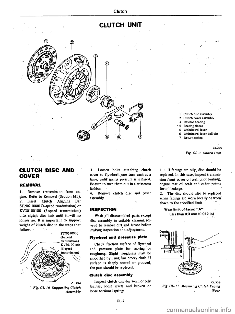
CLUTCH
DISC
AND
COVER
REMOVAL
1
Remove
transmission
from
en
gine
Refer
to
Removal
Section
MT
2
Insert
Clutch
Aligning
Bar
ST20610000
4
speed
tranSmission
or
KV30100IOO
5
speed
transmission
into
clutch
disc
hub
until
it
will
no
longer
gd
It
is
important
to
support
weight
of
clutch
disc
in
the
steps
that
follow
ST20610000
4
peed
transmission
KV30100100
S
peed
transmission
S
cL194
Fig
CL
W
Supporting
Clutch
Assembly
Clutch
CLUTCH
UNIT
n
j
3
Loosen
bolts
attaching
clutch
cover
to
flywheel
one
turn
each
at
a
time
until
spring
pressure
is
released
Be
sure
to
turn
them
out
in
a
crisscross
fashion
4
Remove
clutch
disc
and
cover
assembly
INSPECTION
Wash
all
disassembled
parts
except
disc
assembly
in
suiiable
cleaning
sol
vent
to
remove
dirt
and
grease
before
making
inspection
and
adjustment
FI
1
and
pressure
plate
Check
friction
surface
of
flywheel
and
pressure
plate
for
scoring
or
roughness
Slight
roughness
may
be
smoothed
by
using
fine
emery
cloth
If
surface
is
deeply
scored
or
grooved
the
part
should
be
replaced
Clutch
disc
sembi
Inspect
clutch
disc
for
worn
or
oily
facings
loose
rivets
and
broken
or
loose
torsional
springs
CL
7
1
Clutch
disc
assembly
2
Clutch
cover
assembly
3
ReleaJe
bearing
4
Bearing
sleeve
S
Withdrawal
lever
6
Withdrawa11ever
ball
pin
7
Return
spring
CL370
Fig
CL
9
Clutch
Unit
I
If
facings
are
oily
disc
should
be
replaced
In
this
case
inspect
transmis
sion
front
cover
oil
seal
pilot
bushing
engine
rear
oil
seals
and
other
points
for
oil
leakage
2
The
disc
should
also
be
replaced
when
facings
are
worn
locally
or
worn
down
io
ihe
specified
limit
Wear
limit
of
facing
A
Les
than
0
3
mm
0
012
in
9111
I
A
M
m
C
L336
Fig
CL
ll
M
asur
ng
Clutch
Facing
Wear
Page 225 of 548
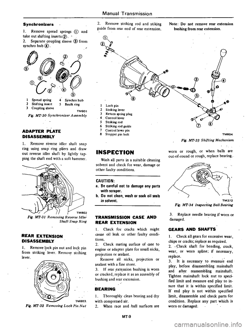
Synchronizers
I
Remove
spread
springs
j
and
take
out
shifting
inserts@
2
Separate
coupling
sleeve
@
from
synchro
hub
@
0
t
j
@
O
LJ
J
1
ID
4
Synchro
hub
S
Baulk
ring
1
Spread
spring
2
Shifting
insert
3
Coupling
sleeve
TMSOl
Fig
MT
30
Synchronjzer
Assembly
ADAPTER
PLATE
DISASSEMBLY
1
Remove
reverse
idler
shaft
snap
ring
using
snap
ri
1g
pliers
and
draw
out
reverse
idler
shaft
by
lightly
tap
ping
the
shaft
end
with
a
soft
hammer
k
Fig
MT
31
Removing
Reverse
Idler
Shaft
Snap
Ring
REAR
EXTENSION
DISASSEMBLY
I
Remove
lock
pin
nut
and
lock
pin
from
striking
1
lever
Remov
str
iking
lever
TM803
Fig
MT
32
Removing
Lock
Pin
Nut
Manual
Transmission
2
Remove
striking
rod
and
stiking
guide
from
rear
end
of
rear
extension
j
1
Lock
pin
2
Striking
lever
3
Return
spring
plug
4
Con
trollevcr
5
Striking
rod
6
Striking
fod
guide
7
Control
Ie
o
eI
pin
8
Stopper
pin
bolt
INSPECTION
Wash
all
parts
in
a
suitable
cleaning
solvent
and
check
for
wear
damage
or
other
faulty
conditions
CAUTION
a
Be
careful
not
to
damage
any
parts
with
scraper
b
Do
not
clean
wash
or
soak
oil
seals
in
solvent
TRANSMISSION
CASE
AND
REAR
EXTENSION
I
Check
for
cracks
which
might
cause
oil
leak
or
other
faulty
condi
tions
2
Check
mating
surface
of
case
to
engine
or
adapter
plate
for
small
nicks
projection
or
sealant
Remove
all
nicks
projection
or
sealant
with
a
fine
stone
3
If
rear
ext
nsion
bushing
is
worn
or
cracked
replace
it
as
an
assembly
of
bushing
and
rear
extension
BEARING
Thoroughly
clean
bearing
and
dry
with
compressed
air
2
When
race
and
ball
surfaces
are
MT
9
Note
Do
not
remove
rear
extension
bushing
from
rear
extension
@
TM804
Fig
MT
33
Shifting
Mechanism
worn
or
rough
or
when
balls
are
out
of
round
or
rough
replace
bearing
TM372
Fig
MT
34
In
pecting
Ball
Bearing
3
Replace
needle
bearing
if
worn
or
damaged
GEARS
AND
SHAFTS
I
Check
all
gears
for
excessive
wear
chips
or
cracks
replace
as
required
2
Check
shaft
for
bending
crack
wear
or
worn
spline
if
necessary
replace
3
It
is
necessary
to
measure
end
play
before
disassembling
mainshaft
and
after
reassembling
rnainshaft
Tighten
mainshaft
lock
nut
to
speci
fied
limit
and
measure
end
play
to
in
sure
that
it
is
within
specified
limit
If
end
play
is
not
within
specified
limit
disassemble
and
check
parts
for
condition
Replace
any
part
which
is
worn
or
damaged
Page 278 of 548
4
Bolt
converter
to
drive
plate
Note
Align
chalk
mark
painted
a
cro5S
both
parts
during
disas
sembling
p
S
After
converter
is
installed
rotat
r
nkshait
veral
turns
and
check
to
be
sure
that
transmission
rotates
freely
without
binding
6
Pour
recommended
automatic
transmission
fluid
up
to
correct
level
through
oil
charge
pipe
7
Connect
manual
lever
to
shift
rod
Operation
should
be
carried
out
with
m
mual
and
selector
levers
in
N
8
Connect
inhibitor
switch
wires
Automatic
Transmission
NOte
a
Refer
to
page
AT40
for
Checking
and
Adjusting
Inhibitor
Switch
b
Inspect
end
edjust
switch
as
abo
whe
ever
it
has
to
be
removed
for
servi
e
9
Check
inhibitor
switch
for
op
eration
Starter
should
be
brought
into
op
eration
only
when
selector
lever
is
in
P
and
N
positions
it
should
not
be
started
when
lever
is
in
D
n
and
Ru
positions
Back
up
lamp
should
Iso
light
when
selector
lever
is
placed
in
R
position
10
Check
level
of
oil
in
transm
sion
For
detailed
procedure
see
page
AT39
AT
26
II
Move
selector
leve
through
all
positions
to
be
sure
that
transmission
operates
correctly
With
hand
brake
applied
rotate
engine
at
idling
Without
disturbing
the
above
seUlng
move
selector
lever
through
N
to
D
to
2
to
I
and
to
R
A
slight
shock
should
be
reU
by
handgripping
selector
each
time
transmission
is
shifted
Note
See
page
AT40
for
Checking
Engine
Idling
Revolution
12
Check
to
be
sure
that
line
pres
sure
is
correct
To
do
this
refer
to
page
AT
43
for
Line
Pressure
Test
13
Perform
stan
test
as
described
in
page
AT41
Page 292 of 548
Place
the
vehicle
in
a
pit
and
by
sampling
the
lealeed
oil
deiermine
if
it
is
the
torque
converter
oil
The
torque
converter
oil
has
a
color
like
red
wine
so
it
is
easily
distinguished
from
engine
oil
or
gear
oil
Wipe
off
the
lealeing
oil
and
dust
and
detect
the
spot
of
ill
lell8e
nonflammable
organic
solvent
such
as
carbon
tetrachloride
for
wiping
Raise
the
oil
tcmperature
by
op
erating
the
engine
and
shift
the
lever
to
D
to
increase
the
oil
pressure
The
sp
Q
of
o
1
1I8
u
J1en
be
found
more
easily
Note
As
oil
leakage
from
the
breath
er
does
not
talee
place
except
when
running
at
high
peed
it
iSimpos
sible
to
ate
this
lealcage
with
vehicle
stationary
CHECKING
ENGINE
IDLING
REVOLunON
The
engine
idling
revolution
should
be
properly
adjusted
If
the
engine
revolution
is
too
low
the
e
gine
does
not
operate
smoothly
and
if
too
high
a
strong
shocle
or
creep
develops
when
changing
over
from
ON
to
Dn
or
R
CHECKING
AND
ADJUSTING
KICK
WN
SWITCH
AND
DOWNSH
FT
SOLENOID
When
the
Ieickdown
operation
is
not
made
properly
or
the
speed
chang
ingpoint
is
too
high
check
the
kick
down
switch
downshift
solenoid
and
wiring
between
them
When
the
igni
tion
Ieey
is
po
iti
ned
at
the
1st
stage
and
the
accelerator
pedal
is
depressed
deeply
the
switch
contact
hould
be
closed
and
the
solenoid
should
clicle
If
it
does
not
click
it
indicates
a
defect
Then
check
each
part
with
the
testing
inatrumen15
Auto
lT1atic
Transmissiqn
Fi
J
A
T
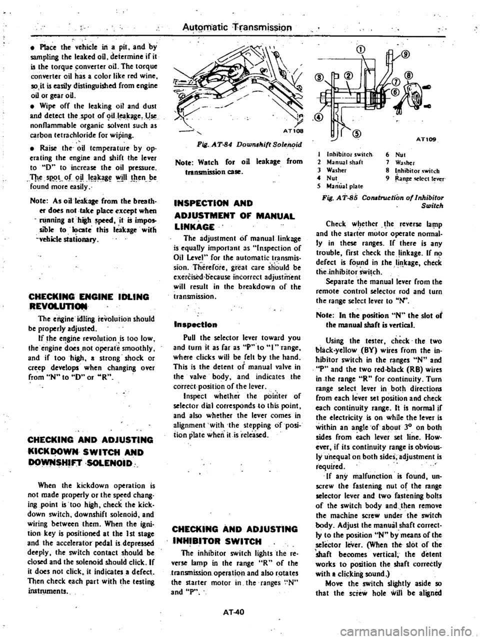
84
Down
ltift
Sole
id
Note
Watch
for
oil
leekage
from
tnnsmission
case
INSPECTION
AND
ADJUSTMENT
OF
MANUAL
LINKAGE
The
adjustmcnt
of
manual
linkage
i
equany
important
as
Inspection
of
Oil
Level
for
the
automatic
transmis
sion
Therefore
great
care
should
be
cxercised
oecause
incorrect
adjustment
will
result
in
the
breakdown
of
the
transmission
Inspection
pun
the
selector
lever
toward
you
and
turn
it
as
far
as
p
to
range
where
clicks
will
be
ell
by
the
hand
This
is
the
detent
of
manual
valve
in
the
valve
body
and
indicates
the
corrett
position
of
the
lever
Inspect
whether
the
pointer
of
selector
dial
corresponds
to
this
point
and
also
whether
the
lever
comes
in
alignment
with
the
stepping
of
posi
iion
plate
when
itis
released
CHECKING
AND
ADJUSTING
INHIBITOR
SWITCH
The
inhibitor
switch
lights
the
re
verse
lamp
in
the
range
R
of
the
transmission
operation
and
also
rotates
the
starter
motor
in
the
ranges
N
and
P
AT
40
i
j
tI
IlV
@
@
AT
I
Inhibitor
switch
2
Manual
shaft
3
Washer
4
Nut
5
Manual
plate
Fi
J
AT
85
Comtruction
of
Inhibitor
Switch
6
Nut
1
Washer
8
Inhibitor
wilch
9
Ran
q
Iect
lever
Check
w
ethcr
he
leverse
lal
1p
and
the
starter
motor
operate
nonnal
Iy
in
these
ranges
If
there
is
any
trouble
first
check
the
inkage
If
no
defect
is
fo
nd
in
the
Ii
leage
check
tlie
inhibitor
Swi
ch
Separate
the
manual
lever
from
the
remote
control
selector
rod
and
turn
the
range
select
lever
to
N
Note
In
the
position
N
the
slot
of
the
manual
shaft
is
vertical
Using
the
tester
check
the
two
black
yellow
BY
wire
from
the
in
hibitor
switch
in
the
ranges
N
and
p
and
the
two
red
blacle
RB
wires
in
the
lange
R
for
continuity
Turn
range
select
lever
in
both
directions
from
each
lever
set
position
and
check
each
continuity
range
It
is
normal
if
the
electricity
is
on
while
the
lever
is
within
an
angle
of
about
30
on
both
sides
from
each
lever
set
line
How
ever
if
its
continuity
range
is
obvioUs
ly
u
nequal
on
both
sides
adjustment
is
required
If
any
malfunction
is
found
un
screw
the
fastening
nut
o
the
range
selector
lever
and
two
fastening
bolts
of
the
switch
body
and
then
remove
the
machine
screw
under
the
switch
body
Adjust
the
manual
shaft
correct
Iy
to
the
position
N
by
means
of
the
selector
leVer
When
the
slot
of
the
shaft
becomes
vertical
the
detent
worles
to
position
the
shaft
correctly
with
a
clicking
sound
Move
the
switch
slightly
aside
so
that
the
scie
hole
will
be
aligned
Page 407 of 548
Engine
Control
Fuel
Exhaust
Systems
8
Remove
front
exhaust
tube
from
exhaust
manifold
NON
CALIFORNIA
MODELS
EXCEPT
FU
MODEL
I
Temporarily
loosen
nuts
securing
front
exhaust
tube
assembly
to
ex
haust
manifold
2
Remove
front
exhaust
tube
as
sembly
from
exhaust
mounting
brack
et
3
Temporarily
loosen
bolts
securing
exhaust
mounting
insulator
to
body
and
remove
bolts
securing
muffler
lower
clamp
and
muffler
to
muffler
upper
clamp
4
Remove
exhaust
tube
clip
5
Break
sealant
off
the
front
tube
to
rear
tube
connection
Note
A
sealant
is
applied
to
the
tube
connections
to
eliminate
the
leak
age
of
exhaust
gases
Observe
the
procedures
outlined
later
in
this
section
as
a
guide
6
Remove
front
tube
from
exhaust
manifold
then
remove
rear
tube
from
car
Refer
to
California
Models
and
FU
Model
for
removal
When
disconnecting
the
exhaust
tube
connections
observe
the
follow
ing
parts
I
Break
old
sealant
off
the
con
nection
by
lightly
tapping
around
the
tube
with
a
hammer
and
twisting
muffler
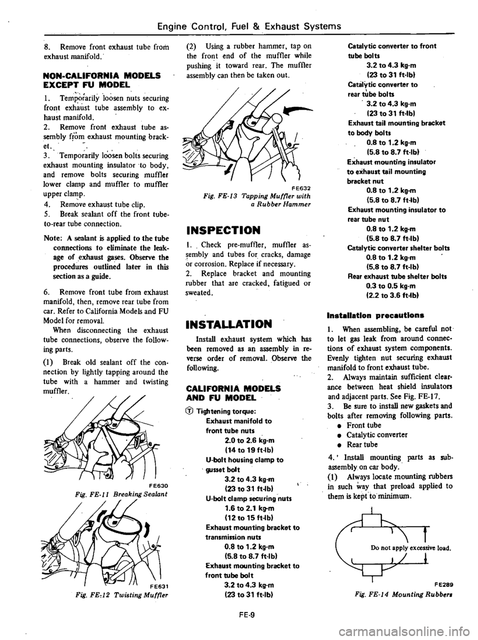
F
E630
Fig
FE
11
Breaking
Sealant
Fig
FEd
2
2
Using
a
rubber
hammer
tap
on
the
front
end
of
the
muffler
while
pushing
it
toward
rear
The
muffler
assembly
can
then
be
taken
out
FE632
Fig
FE
13
Tapping
Muffler
with
a
Rubber
Hammer
INSPECTION
I
Check
pre
muffler
muffler
as
sembly
and
tubes
for
cracks
damage
or
corrosion
Replace
if
necessary
2
Replace
bracket
and
mounting
rubber
that
are
cracked
fatigued
or
sweated
INSTALLATION
Install
exhaust
system
which
has
been
removed
as
an
assembly
in
re
verse
order
of
removal
Observe
the
following
CALIFORNIA
MODELS
AND
FU
MODEL
1Jl
Tightening
torque
Exhaust
manifold
to
front
tube
nuts
2
0
to
2
6
kg
m
14
to
19
fHb
U
bolt
housing
clamp
to
gusset
bolt
3
2
to
4
3
kg
m
23
to
31
ft
bl
U
bolt
clamp
securing
nuts
1
6
to
2
1
k
l
m
12
to
15
ft
bl
Exhaust
mounting
bracket
to
transmission
nuts
0
8
to
1
2
kg
m
5
8
to
8
7
ft
Ibl
Exhaust
mounting
bracket
to
front
tube
bolt
3
2
to
4
3
k
l
m
23
to
31
ft
Ib
FE
9
CatalytiC
converter
to
front
tube
bolts
3
2
to
4
3
kg
m
23
to
31
ft
Ibl
Catalytic
converter
to
rear
tUbe
bolts
3
2
to
4
3
kg
m
23
to
31
ft
Ibl
Exhaust
tail
mounting
bracket
to
body
bolts
0
8
to
1
2
kg
m
5
B
to
8
7
ft
Ibl
Exhaust
mounting
insulator
to
exhaust
tail
mounting
bracket
nut
0
8
to
1
2
kg
m
5
8
to
8
7
ft
Ib
Exhaust
mounting
insulator
to
rear
tube
nut
O
B
to
1
2
kg
m
5
8
to
8
7
ft
Ib
Catalytic
converter
shelter
bolts
O
B
to
1
2
kg
m
5
8
to
B
7
ft
Ib
Rear
exhaust
tube
shelter
bolts
0
3
to
0
5
kg
m
2
2
to
3
6
ft
bl
Installation
precautions
I
When
assembling
be
careful
not
to
let
gas
leak
from
around
connec
tions
of
exhaust
system
components
Evenly
tighten
nut
securing
exhaust
manifold
to
front
exhaust
tube
2
Always
maintain
sufficient
clear
ance
between
heat
shield
insulators
and
adjacent
parts
See
Fig
FE
I7
3
Be
sure
to
install
new
gaskets
and
bolts
after
removing
following
parts
Front
tube
Catalytic
converter
Rear
tube
4
Install
mounting
parts
as
sub
assembly
on
car
body
I
Always
locate
mounting
rubbers
in
such
way
that
preload
applied
to
them
is
kept
to
minimum
f
Do
not
apply
excessive
load
I
F
E289
Fig
FE
J4
Mounting
Rubbe
Page 450 of 548
m
c
n
to
l
l
I
g
iF
0
1
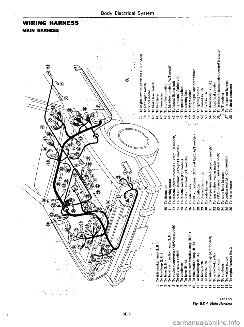
To
side
marker
lamp
L
H
2
To
headlamp
L
H
3
To
horn
L
H
4
To
front
combination
lamp
L
H
5
To
cooler
co
pressor
Air
Con
models
6
To
oil
pressure
switch
7
To
condenser
8
To
horn
R
H
9
To
front
combination
la
t11p
R
H
10
To
side
marker
lamp
R
H
11
To
headlamp
R
H
12
To
body
earth
13
To
fusible
link
14
To
inhibitor
relay
AfT
model
15
To
aut6
choke
relay
16
To
ignition
coil
17
To
condenser
18
To
washer
motor
19
To
engine
harness
No
2
@
20
To
alternator
21
To
starting
motor
22
To
throttle
opener
solenoid
Except
FU
models
23
To
fuel
cut
solenoid
Except
FU
models
24
To
throttle
switch
FU
models
25
To
fuel
cut
solenoid
FU
models
26
To
auto
choke
27
To
VC
cut
solenoid
M
T
and
Calif
AfT
models
28
To
distributor
29
To
thermal
transmitter
30
To
body
harness
31
To
low
pressure
switcn
Air
Con
models
32
To
rear
window
washer
motor
33
To
FICO
solenoid
Air
Con
models
34
To
room
lamp
harness
35
To
cooling
unit
Air
C
on
models
36
To
heater
motor
37
To
engine
revolution
switch
FU
models
38
To
rear
wiper
switch
39
To
wiper
motor
40
To
brake
level
switch
41
To
belt
timer
42
To
horn
relay
43
To
stop
lamp
switch
44
To
kickdown
switch
AfT
model
45
To
hazard
flasher
unit
46
To
turn
signal
flasher
unit
47
To
ignition
switch
48
To
steering
lock
49
To
wiper
switch
50
To
turn
signal
and
hC
rn
switch
51
To
lighting
switch
5i
To
hazard
switch
53
To
belt
switch
54
To
door
switch
L
H
55
To
hand
brake
switch
56
To
automatic
transmission
control
indicator
AfT
models
57
To
instrument
harness
58
To
check
connector
I
0
i
a
z
Z
G
z
tIl
tIl
a
Z
Il
I
to
o
Co
m
16
n
n
OJ
1
3
Page 467 of 548
B6
Y
Electrica
System
f
EIIII
I
I
I
11111111
111
777
Rea
window
1
j
glass
W
777
n
1
r7
U
u
T
t
I
I
I
j
T
cD
t
ID
3
BE537
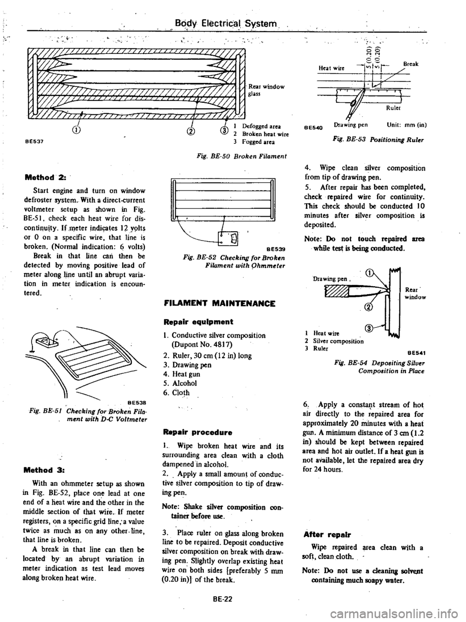
Method
2
Start
engine
and
turn
on
window
defroster
system
With
a
direct
current
voltmeter
setup
as
shown
in
Fig
BE
51
check
each
heat
wire
for
dis
continuity
lfmeter
indic
ates
12
Y9lts
or
0
on
a
specific
wire
that
line
is
broken
Normal
indication
6
volts
Break
in
that
line
can
then
be
detected
by
moving
positive
lead
of
meter
along
line
until
an
abrupt
varia
tion
in
meter
indication
is
encoun
teredo
Fig
BE
51
Method
3
With
an
ohmmeter
setup
as
shown
in
Fig
BE
52
place
one
lead
at
one
end
of
a
heat
wire
and
the
other
in
the
middle
section
of
that
wire
If
meter
registers
on
a
specific
grid
line
a
value
twice
as
much
8S
on
any
other
line
that
line
is
broken
A
break
in
tha
t
line
can
then
be
located
by
an
abrupt
variation
in
meter
indication
as
test
lead
moves
along
broken
heat
wire
Defogged
area
Broken
heat
wire
Fogged
area
Fig
BE
50
Broken
Filament
n
I
I
SE539
Fig
BE
52
Checking
for
Broken
Filament
with
phmmder
FILAMENT
MAINTENANCE
Repair
equipment
I
Conductive
silver
composition
Dupont
No
4817
2
Ruler
30
em
12
in
long
3
Drawing
pen
4
Heat
gun
5
Alcohol
6
Cloth
Repair
procedure
I
Wipe
broken
heat
wire
and
its
surrounding
area
clean
with
a
cloth
dampened
in
alcohol
2
Apply
a
small
amount
of
conduc
tive
silver
composition
to
tip
of
draw
ing
pen
Note
Shake
silver
composition
con
tainer
before
use
3
Place
ruler
on
glass
along
broken
line
to
be
repaired
Deposit
conductive
silver
composition
on
break
with
draw
ing
pen
Slightly
overlap
existing
heat
wire
on
both
sides
preferably
5
mm
0
20
in
of
the
break
BE
22
88
N
N
cci
4
r
reak
Heat
wire
I
I
L
r
GJ
I
Ruler
BE540
Ora
wing
pen
Unit
mm
in
Fig
BE
53
Pmitioning
Ruler
4
Wipe
clean
silver
composition
from
tip
of
drawing
pen
5
After
repair
has
been
completed
check
repaired
wire
for
continuity
This
check
should
be
conducted
10
minutes
after
silver
composition
is
deposited
Note
Do
not
touch
repaired
area
while
test
is
being
conducted
Drawing
pen
Rear
window
1
Heat
wire
2
Silver
composition
3
Ruler
@
iI
aE541
Fig
BE
54
Depositing
Silver
Compo
ition
in
Place
6
Apply
a
consla11t
stream
of
hot
air
directly
to
the
repaired
area
for
approxUnately
20
minutes
with
a
heat
gun
A
minilnum
distance
of
3
em
1
2
in
should
be
kept
between
repaired
area
and
hot
air
outlet
If
a
heat
gun
is
not
available
let
the
repaired
area
dry
for
24
hours
After
repair
Wipe
repaired
area
clean
with
a
soft
clean
cloth
Note
Do
not
use
a
cleaning
solvt
nt
containing
much
soapy
water
Page 491 of 548
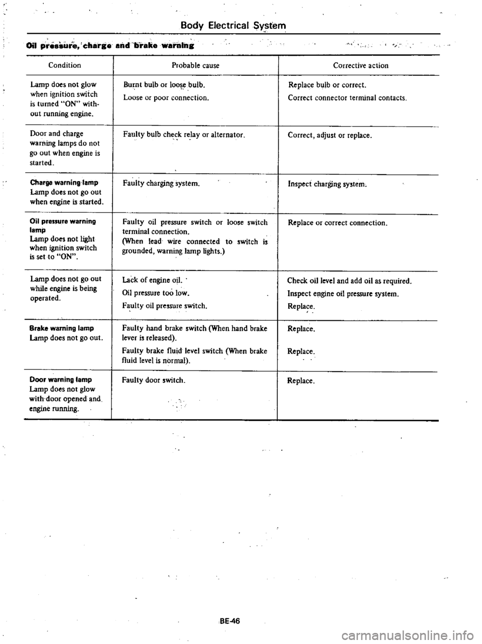
Body
Electrical
Sy
tem
Oil
pr
re
charg
and
brake
warillng
Condition
Lamp
does
not
glow
when
ignition
switch
is
turned
ON
with
out
running
engine
Door
and
charge
warning
lamps
do
not
go
out
when
engine
is
started
Charge
waming
amp
Lamp
does
not
go
out
when
engine
is
started
Oil
pressure
warning
lamp
Lamp
does
not
light
when
ignition
switch
is
set
to
ON
Lamp
does
not
go
out
while
engine
is
being
operated
Brake
warning
lamp
Lamp
does
not
go
out
Door
warning
lamp
Lamp
does
not
glow
with
door
opened
and
engine
running
Probable
cause
Burnt
bulb
or
loo
ebulb
Loose
or
poor
connection
Faully
bulb
check
relay
or
alternator
Faully
charging
system
Faully
oil
pressure
switch
or
loose
switch
terminal
connection
When
lead
wire
connected
to
switch
is
grounded
warning
lamp
lights
Lack
of
engine
oil
Oil
pressure
too
low
Faully
oil
pressure
switch
Faulty
hand
brake
switch
When
hand
brake
lever
is
released
Faully
brake
fluid
level
switch
When
brake
fluid
level
is
normal
Faully
door
switch
BE
46
Corrective
action
Replace
bulb
or
correct
Correct
connector
terminal
contacts
Correct
adjust
or
replace
Inspect
charging
system
Replace
or
correct
connection
Check
oil
level
and
add
oil
as
required
Inspect
engine
oil
pressure
system
Replace
Replace
Replace
Replace