height DATSUN 210 1979 Owner's Manual
[x] Cancel search | Manufacturer: DATSUN, Model Year: 1979, Model line: 210, Model: DATSUN 210 1979Pages: 548, PDF Size: 28.66 MB
Page 307 of 548

DATSUN
2JO
Model
83
J
0
Series
SECTIONPD
PROPELLER
SHAFT
DIFFERENTIAL
CARRIER
CONTENTS
PROPELLER
SHAFT
INSPECTION
GENERAL
INSPECTION
PROPEllER
SHAFT
VIBRATION
REMOVAL
AND
INSTAllATION
REMOVAL
INSTAllATION
DIFFERENTIAL
CARRIER
REMOVAL
PRE
DISASSEMBl
Y
INSPECTION
DISASSEMBLY
FINAL
DRIVE
ASSEMBLY
DIFFERENTIAL
CASE
INSPECTION
ASSEMBl
Y
AND
ADJUSTMENT
PRECAUTIONS
IN
REASSEMBLY
ASSEMBLY
OF
DIFFERENTIAL
CASE
ADJUSTMENT
OF
DRIVE
PINION
HEIGHT
ADJUSTMENT
OF
DRIVE
PINION
PRELOAD
PD
2
PD
2
PD
2
PD
2
PD
2
PD
2
PD
2
PD
3
PD
3
PD
3
PD
4
PD
4
PD
4
PD
4
PD
5
PD
5
PD
5
PD
6
PD
6
AQJUSTMENT
OF
SIDE
BEARING
SHIMS
INSTAllATION
REPLACEMENT
OF
FRONT
Oil
SEAL
SERVICE
DATA
AND
SPECIFICATIONS
PROPEllER
SHAFT
GENERAL
SPECIFICATIONS
SERVICE
DATA
TIGHTENING
TORQUE
DIFFERENTIAL
CARRIER
GENERAL
SPECIFICATIONS
SERVICE
DATA
TIGHTENING
TORQUE
TROUBLE
DIAGNOSES
AND
CORRECTIONS
PROPEllER
SHAFT
DIFFERENTIAL
CARRIER
SPECIAL
SERVICE
TOOLS
PD
7
PD
9
PD
9
PD
lO
PD
lO
PD
lO
PD
lO
PD
lO
PD
l0
PD
lO
PD
ll
PD
ll
PD
12
PD
12
PD
13
PD
15
Page 309 of 548
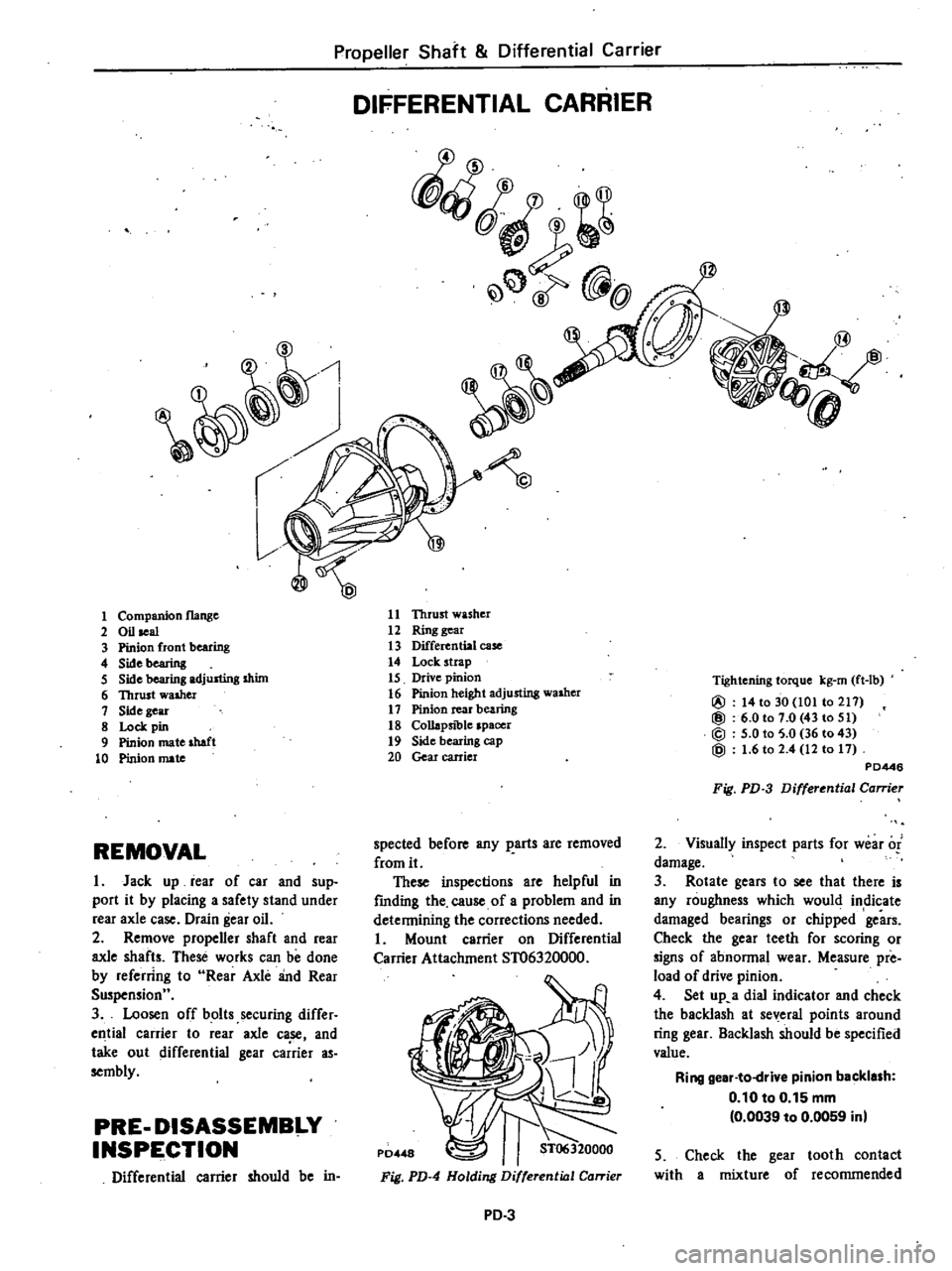
Propeller
Shaft
Differential
Carrier
DIFFERENTIAL
CARRIER
fQ
@
1
11
Thrust
washer
12
Ring
gear
13
Differential
case
14
Lock
strap
15
Drive
pinion
16
Pinion
height
adjusting
washer
17
Pinion
rear
bearing
18
Collapsible
spacer
19
Side
bearing
cap
20
Gear
carrier
1
Companion
flange
2
Oil
seal
3
Pinion
front
bearing
4
Sidebearing
5
Side
bearing
adjusting
shim
6
Thrust
walher
1
Side
gear
8
Lock
pin
9
Pinion
mate
shaft
10
Pinion
mate
Tightening
torque
kg
rn
ft
lb
@
14
to
30
101
to
211
@
6
0101
0
43
to
51
@
5
0
to
5
0
36
to
43
@
1
6
to
2
4
12
to
11
PD446
Fig
PD
3
Differential
Carrier
2
Visuany
inspect
parts
for
wear
of
damage
3
Rotate
gears
to
see
that
there
is
any
roughness
which
would
indicate
damaged
bearings
or
chipped
gears
Check
the
gear
teeth
for
scoring
or
signs
of
abnonnal
wear
Measure
pre
load
of
drive
pinion
4
Set
up
a
dial
indicator
and
check
the
backlash
at
several
points
around
ring
gear
Backlash
should
be
specified
value
Ring
gear
to
drive
pinion
backlash
0
10
to
0
15
mm
0
0039
to
0
0059
inl
spected
before
any
parts
are
removed
from
it
These
inspections
are
helpful
in
fmding
the
cause
of
a
problem
and
in
detennining
the
corrections
needed
Mount
carrier
on
Differential
Carrier
Attachment
ST06320000
REMOVAL
I
Jack
up
rear
of
car
and
sup
port
it
by
placing
a
safety
stand
under
rear
axle
case
Drain
gear
oil
2
Remove
propener
shaft
and
rear
axle
shafts
These
works
can
be
done
by
referring
to
Rear
Axle
and
Rear
Suspensionu
3
Loosen
off
bolts
securing
differ
ell
tial
carrier
to
rear
axle
ca
se
and
take
out
differential
gear
carrier
as
sembly
PRE
DISASSEMBI
Y
INSPE
CTION
Differential
carrier
should
be
in
5
Check
the
gear
tooth
contact
with
a
mixture
of
recommended
Fig
PD
4
Holding
Differential
Carrier
PD
3
Page 312 of 548

ADJUSTMENT
OF
DRIVE
PINION
HEIGHT
Adjust
the
pinion
height
with
wash
er
provided
between
rear
bearing
inner
race
and
the
back
of
piliion
gear
J
Press
fit
front
and
rear
bearing
outer
races
into
gear
carrier
using
Drive
Pinion
Outer
Race
Drift
STJ070
I
000
and
Bar
ST30611000
2
Fit
rear
bearing
on
gear
carrier
and
install
Dwnmy
Shaft
on
rear
bear
ing
and
place
Height
Gauge
on
gear
carrier
STJII21000
Height
gauge
KV38
103500
Height
gauge
spacer
ST3
II
22000
Dummy
shaft
KV3gl03600
Dummy
shaft
spacer
ST3112tOOO
PD461
Fig
PD
14
AqjUlting
Pinion
Height
3
Measure
the
clearance
N
be
tween
the
tip
end
of
height
gauge
and
the
end
surface
of
dummy
shaft
using
a
thickness
gauge
P0322
Fig
PD
15
Meo
uring
Clearance
4
The
proper
thickness
of
pinion
height
adjusting
washers
can
be
obtain
ed
from
the
following
formula
Propeller
Shaft
Differential
Carrier
T
W
N
HxO
01
OJ8
Where
T
Required
thickness
of
pinion
heightedjusting
w
shers
W
Thickness
of
temporarily
insert
ed
washer
mm
Be
sure
to
use
washer
of
2
74
0
1079
or
2
77
0
1091
or
2
80
0
1102
mm
in
thick
ness
N
Measured
clearance
between
height
gauge
and
dummy
shaft
face
mm
H
Figure
marked
on
the
drive
pinion
head
Note
e
Figure
H
is
e
dimensional
variation
in
units
of
1
100
mm
egainst
stand
ard
measurement
b
If
value
signifying
H
is
not
given
regard
it
as
zero
and
compute
Head
number
Hl
P0186
Set
number
Fig
PD
16
Variation
Number
on
Drive
Pinion
Examples
of
calculation
EX
I
W
2
74mmN
0
30mmH
1
T
W
N
H
x
0
01
0
18
2
74
0
30
I
x
0
01
OJ8
3
04
0
19
2
85
The
correct
washer
thickness
is
2
86
mm
EX
2
W
2
77
mm
N
0
21
mm
H
0
T
W
N
HxO
01
OJ8
2
77
0
21
OxO
0I
OJ8
2
98
0
18
2
80
The
correct
washer
thickness
is
2
g0
mm
PD
6
EX
3
W
2
80
mm
N
0
48
mm
H
2
T
W
N
HxO
OI
OJg
2
80
OA8
2
x
0
01
OJ8
3
28
0
20
3
08
The
correct
washer
thickness
is
3
07
mm
Pinion
height
adjusting
washer
Thickness
mm
in
2
74
OJ
079
3
01
0
1185
2
77
OJ09I
3
04
0
1197
2
80
OJ
102
3
07
0
1209
2
83
0
1114
3
10
0
1220
2
86
OJ
126
3J3
0
1232
2
89
0
1138
3
16
0
1244
2
92
OJ
150
3
19
0
1256
2
95
0
1161
3
22
OJ
268
2
98
0
1173
3
25
O
l2g0
5
Fit
detennined
pinion
height
ad
justing
washer
in
drive
pinion
and
press
fit
rear
bearing
inner
race
in
it
using
Drive
Pinion
Bearing
Drift
Bar
STJ0600000
Note
After
assembly
check
to
see
thet
tooth
contact
is
correct
If
Dot
readjust
ADJUSTMENT
OF
DRIVE
PINION
PRELOAD
Adjust
the
preload
of
drive
pinion
with
collapsible
spacer
This
procedure
has
nothing
to
do
with
thickness
of
pinion
height
ad
justing
washer
Note
Collapsible
spacer
oil
seal
and
pinion
nut
cannot
be
reused
I
After
adjusting
pinion
height
lubricate
front
bearing
with
gear
oil
and
place
it
in
gear
carrier
2
Install
a
new
oil
seal
in
gear
carrier
using
Oil
Seal
Fitting
Tool
ST33400001
Lubricate
cavity
between
seal
lips
with
recommended
multi
purpose
grease
when
installing
3
Place
a
new
collapsible
spacer
on
Page 317 of 548
Propeller
Shaft
Differential
Carrier
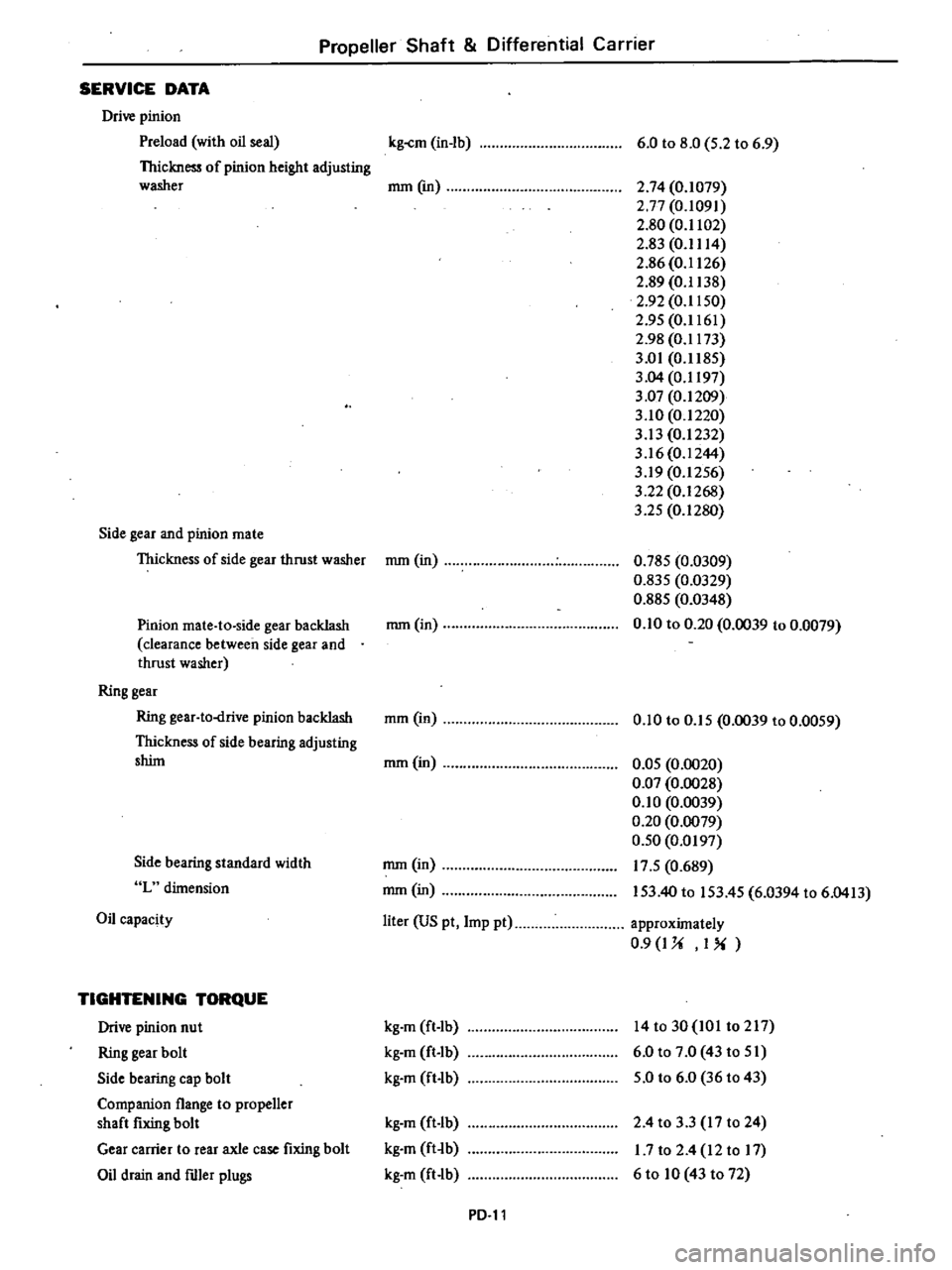
SERVICE
DATA
Drive
pinion
Preload
with
oil
seal
Thickness
of
pinion
height
adjusting
washer
Side
gear
and
pinion
mate
Thickness
of
side
gear
thrust
washer
Pinion
mate
to
side
gear
backlash
clearance
between
side
gear
and
thrust
washer
Ring
gear
Ring
gear
to
drive
pinion
backlash
Thickness
of
side
bearing
adjusting
shint
Side
bearing
standard
width
L
dimension
Oil
capacity
TIGHTENING
TORQUE
Drive
pinion
nut
Ring
gear
bolt
Side
bearing
cap
bolt
Companion
flange
to
propener
shaft
fixing
bolt
Gear
carrier
to
rear
axle
case
fixing
bolt
Oil
drain
and
ftller
plugs
kg
cm
in
lb
6
0
to
8
0
5
2
to
6
9
mm
em
2
74
0
1079
2
77
0
1091
2
80
0
1102
2
g3
0
1114
2
86
0
1126
2
89
0
1138
2
92
0
1150
2
95
0
1161
2
98
0
1173
3
01
0
1185
3
04
0
1197
3
07
0
1209
3
10
0
1220
3
13
0
1232
3
16
0
1244
3
19
0
1256
3
22
0
1268
3
25
0
1280
mm
in
0
785
0
0309
0
835
0
0329
0
885
0
0348
0
10
to
0
20
0
0039
to
0
0079
mmOn
mm
in
0
10
to
0
15
0
0039
to
0
0059
mm
in
0
05
0
0020
0
Q7
0
0028
0
10
0
0039
0
20
0
0079
0
50
0
0197
17
5
0
689
153
40
to
153
45
6
0394
to
6
0413
mm
in
mm
in
liter
US
pt
Imp
pt
approximately
0
9
I
U
I
kg
m
ft
Ib
kg
m
ft
Ib
kg
m
ft
lb
14to30
IOI
t0217
6
0
to
7
0
43
to
51
5
0
to
6
0
36
to
43
kg
m
ft
Ib
kg
m
ft
b
kg
m
ft
lb
2
4
to
3
3
17
to
24
1
7
to
2
4
12
to
17
6
to
10
43
to
72
PD
ll
Page 322 of 548

Propeller
Shaft
o
ifferential
Carrier
Tool
number
tool
name
ST3070
I
000
Drive
pinion
outer
race
drift
5
ST3112S000
Drive
pinion
setting
gauge
set
Height
gauge
Dummy
shaft
CD
ST31121
000
@ST31122000
@
KV38103500
Height
gauge
spacer
KV38103600
Dummy
shaft
spacer
@
IKent
Mooro
No
Reference
page
or
Fig
No
Unit
applic
auon
J
25742
2
Pag
PD
6
J
25269
01
CD
J
25269
01
@
J
25269
01
Fig
PD
14
Fig
PD
14
Fig
PD
14
Tool
number
tool
name
ST30600000
Drive
pinion
bearing
drift
bar
ST33400001
Oil
seal
fitting
tool
ST3127S000
Preload
gauge
CD
GG91030000
Torque
wrench
@
HT62940000
Socket
adapter
ID
HT6290oo00
Socket
adapter
t
t
o
H172400000
Slide
hammer
I
K
e
nt
Moore
No
Reference
page
or
Fig
No
Unit
application
J
25741
P
1ge
PD
6
I
J
26082
Page
PD
6
J
25765
CD
J
25765
@
ID
Page
PD
7
Page
PD
4
PD
16
Applicable
to
all
8310
series
models
Page 354 of 548
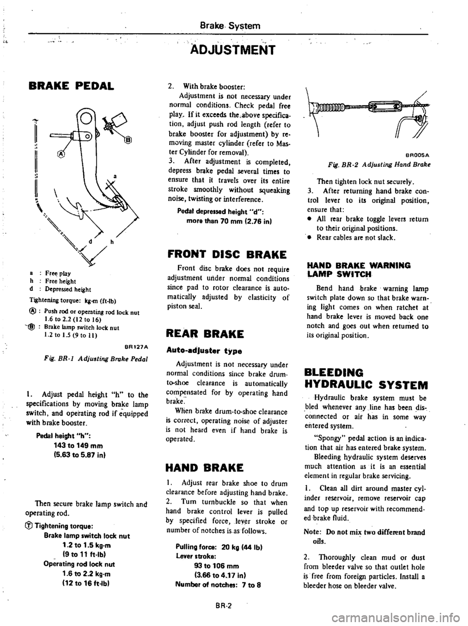
BRAKE
PEDAL
a
a
Fr
play
h
Free
height
d
Depressed
height
Tightening
torque
Icg
m
ft
tb
@
@
Push
rod
or
operating
rod
lock
nut
1
6
to
2
2
12
to
16
Brake
lainp
switch
lock
nut
1
2
to
I
5
9
to
11
BR121A
Fig
BR
1
Adjusting
Broke
Pedal
I
Adjust
pedal
height
h
to
the
specifications
by
moving
brake
lamp
switch
and
operating
rod
if
equipped
with
brake
booster
Pedal
height
h
143
to
149
mm
5
63
to
5
87
inl
Then
secure
brake
lamp
switch
and
operating
rod
C
l
Tightening
tOlque
Blake
lamp
witch
lock
nut
1
2
to
1
5
kg
m
9
to
11
ft
lb
Operating
lad
lock
nut
1
6
to
2
2
kg
m
12
to
16
ft
b
Brake
System
ADJUSTMENT
2
With
brake
booster
Adjustment
is
not
necessary
under
normal
conditions
Check
pedal
free
play
If
it
exceeds
the
above
specifica
tion
adjust
push
rod
length
refer
to
brake
booster
for
adjustment
by
re
moving
master
cylinder
rerer
to
Mas
ter
Cylinder
for
removal
3
After
adjustment
is
completed
depress
brake
pedal
several
times
to
ensure
that
it
travels
over
its
entire
stroke
smoothly
without
squeaking
noise
twisting
or
interference
Pedal
depr
d
Might
d
more
than
70
mm
2
76
in
FRONT
DISC
BRAKE
Front
disc
brake
does
not
require
adjustment
under
normal
conditions
since
pad
to
rotor
clearance
is
auto
malically
adjusted
by
elasticity
of
piston
seal
REAR
BRAKE
Auto
edJuster
type
Adjustment
is
not
necessary
under
normal
conditions
since
brake
drum
t
shoe
clearance
is
automatically
compensated
for
by
operating
hand
brake
Wlien
brake
drum
to
shoe
clearance
is
correct
operating
noise
of
adjuster
is
not
heard
even
if
hand
brake
is
operated
HAND
BRAKE
I
Adjust
rear
brake
shoe
to
drum
clearance
before
adjusting
hand
brake
2
Turn
turnbuckle
so
that
when
hand
brake
control
lever
is
pulled
by
specified
force
lever
stroke
or
number
of
notches
is
as
follows
Pulling
fOil
20
kg
44
Ib
lever
stroke
93
to
106
mm
3
66
to
4
17
in
Numbel
of
notches
7
to
8
BR
2
f
BAQ05A
Fig
BR
2
Adjusting
Hand
Brake
Then
tighten
lock
nut
securely
3
After
returning
hand
brake
con
trol
lever
to
its
original
position
ensure
that
e
All
rear
brake
toggle
levers
return
to
their
original
positions
Rear
cables
are
not
slack
HAND
BRAKE
WARNING
LAMP
SWITCH
Bend
hand
brake
warning
lamp
switch
plate
down
so
that
brake
warn
ing
light
comes
on
when
ratchet
at
hand
brake
lever
is
moved
back
one
notch
and
goes
out
when
returned
to
its
original
position
BLEEDING
HYDRAULIC
SYSTEM
Hydraulic
brake
system
must
be
bled
whenever
any
line
has
been
dis
connected
or
air
has
in
some
way
entered
system
Spongy
pedal
action
is
an
indica
tion
that
air
has
entered
brake
system
Bleeding
hydraulic
system
deserves
much
attention
as
it
is
an
essential
element
in
regular
brake
servicing
Clean
all
dirt
around
master
cyl
inder
reservoir
remove
reservoir
cap
and
top
up
reservoir
with
recommend
edbrake
fluid
Note
Do
not
mix
two
different
brand
oils
2
Thoroughly
clean
mud
or
dust
from
bleeder
valve
so
that
outlet
hole
is
free
from
foreign
particles
Install
a
bleeder
hose
on
bleeder
valve
Page 371 of 548
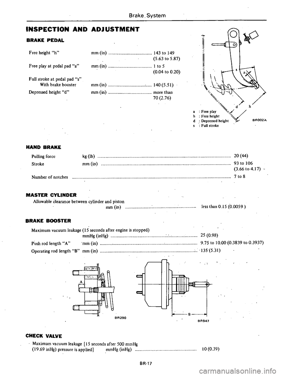
Brake
System
INSPECTION
AND
ADJ
USTMENT
BRAKE
PEDAL
Free
height
h
mm
in
143
to
149
5
63
to
5
87
Free
play
at
pedal
pad
a
mm
in
I
to
5
0
04
to
0
20
Full
stroke
at
pedal
pad
s
With
brake
booster
mm
in
140
5
51
Depressed
height
d
mm
in
more
than
70
2
76
HAND
BRAKE
Pulling
force
Stroke
kg
lb
mm
in
Number
of
notches
MASTER
CYLINDER
Allowable
clearance
between
cylinder
and
piston
mm
in
BRAKE
BOOSTER
Maximum
vacuum
leakage
15
seconds
after
engine
is
stopped
mmHg
inHg
mm
in
mm
in
Push
rod
length
A
Operating
rod
length
8
I
c
tY
1I1
fF
I
BA290
d
IF
CHECK
VALVE
Maximum
vacuum
leakage
15
seconds
after
500
mmHg
19
69
inHg
pressure
is
applied
mmHg
inHg
BR
17
h
d
1
II
II
d
h
Free
play
V
Free
height
Depressed
height
aR002A
Full
stroke
20
44
93
to
106
3
66
to
4
17
7
to
8
less
than
0
15
0
0059
25
0
98
975
to
10
00
0
3839
to
0
3937
135
5
31
1
B
BR947
10
0
39
Page 375 of 548
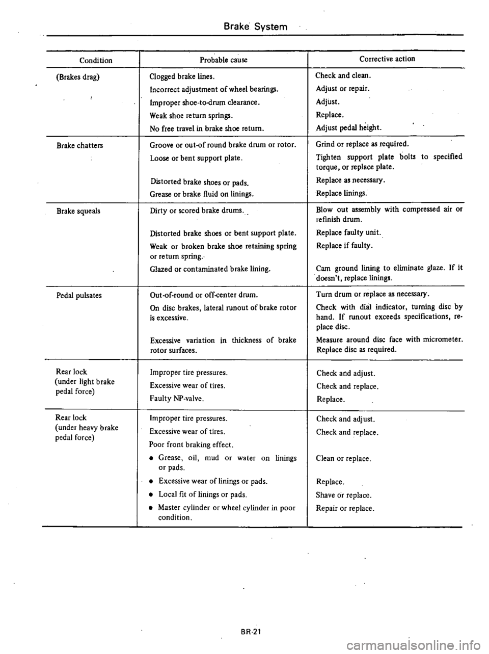
Condition
Brakes
drag
Brake
chatters
Brake
squeals
Pedal
pulsates
Rear
lock
under
light
brake
pedal
force
Rear
lock
under
heavy
brake
pedal
force
Brake
System
Probable
cause
Clogged
brake
lines
Incorrect
adjustment
of
wheel
bearings
Improper
shoe
to
drum
clearance
Weak
shoe
return
springs
No
free
travel
in
brake
shoe
return
Groove
or
out
of
round
brake
drum
or
rotor
Loose
or
bent
support
plate
Distorted
brake
shoes
or
pads
Grease
or
brake
fluid
on
linings
Dirty
or
scored
brake
drums
Distorted
brake
shoes
or
bent
support
plate
Weak
or
broken
brake
shoe
retaining
spring
or
return
spring
Glazed
or
contaminated
brake
lining
Out
of
round
or
off
center
drum
On
disc
brakes
lateral
runout
of
brake
rotor
is
excessive
Excessive
variation
in
thickness
of
brake
rotor
surfaces
Improper
tire
pressures
Excessive
wear
of
tires
Faulty
NP
valve
Improper
tire
pressures
Excessive
wear
of
tires
Poor
front
braking
effect
Grease
oil
mud
or
water
on
linings
or
pads
Excessive
wear
of
linings
or
pads
Local
fit
of
linings
or
pads
Master
cylinder
or
wheel
cylinder
in
poor
condition
BR
2t
Corrective
action
Check
and
clean
Adjust
or
repair
Adjust
Replace
Adjust
pedal
height
Grind
or
replace
as
required
Tighten
support
plate
bolts
to
specified
torque
or
replace
plate
Replace
as
necessary
Replace
linings
Blowout
assembly
with
compressed
air
or
refinish
drum
Replace
faulty
unit
Replace
if
faulty
Cam
ground
lining
to
elilninate
glaze
If
it
doesn
t
replace
linings
Turn
drum
or
replace
as
necessary
Check
with
dial
indicator
turning
disc
by
hand
If
runout
exceeds
specifications
re
place
disc
Measure
around
disc
face
with
micrometer
Replace
disc
as
required
Check
and
adjust
Check
and
replace
Replace
Check
and
adjust
Check
and
replace
Clean
or
replace
Replace
Shave
or
replace
Repair
or
replace
Page 417 of 548

Body
REAR
BUMPER
sP
9
4
h
m
O
1Doo
ter
bumper
1
Rear
ceo
2
Over
rider
3
Side
bumper
brace
4
Center
bumpe
mg
bracket
5
Bumper
moun
6
Bame
plate
r
reinforce
7
Bumpe
ld
Wagon
only
8
Sight
shl
9
Shock
absor
bolt
10
Bumper
atta
mg
BF739B
BF
6
Rear
Bump
r
Fig
INSPECTION
To
inspect
condition
of
bumper
tilize
the
follow
and
shock
absor
e
d
proceed
in
the
h
t
asaguld
mg
c
ar
Good
the
chart
order
indicated
m
Good
Measure
shock
absorber
dimensions
Good
Measure
h
ck
bumper
No
good
bumper
height
Visually
c
e
appearance
Adjust
d
bumper
No
goo
height
Check
shock
No
good
absOrber
operation
compressed
and
expanded
Replace
od
shock
No
go
absorber
Good
BF
6
Page 418 of 548

Bumper
height
I
Place
car
on
a
flat
surface
under
curb
weight
condition
Tires
must
be
inflated
to
rated
pressure
2
Measure
height
above
ground
of
bumper
at
two
mounting
locations
as
shown
in
Figs
BF
7
and
BF
8
3
If
bumper
height
is
not
within
the
specification
loosen
shock
ab
sorber
attaching
bolts
and
nuts
Then
adjust
bumper
height
After
adjust
ment
tighten
bolts
and
nuts
securely
Front
bumper
height
H
360
to
408
mm
14
17
to
16
06
in
Rear
bumper
height
H
Sedan
and
Hatchback
391
to
433
mm
15
39
to
17
05
in
Wagon
376
to
418
mm
14
BO
to
16
46
in
Sedan
and
Hatchback
Body
I
J
S
H
I
BF740B
Fig
BF
7
Front
Bumper
Height
Wagon
O
J
H
j
BF741B
Fig
BF
8
Rear
Bumper
Height
BF
7