spark plugs replace DATSUN 210 1979 Service Manual
[x] Cancel search | Manufacturer: DATSUN, Model Year: 1979, Model line: 210, Model: DATSUN 210 1979Pages: 548, PDF Size: 28.66 MB
Page 18 of 548
pl
ice
mter
as
an
assembly
2
When
installing
oil
mter
tighten
by
hand
Note
Do
not
overtighten
oil
filter
lest
leakage
shoUld
occur
CHANGING
ENGINE
COOLANT
PERMANENT
ANTI
FREEZE
COOLANT
Note
The
permanent
anti
freeze
coolant
is
an
ethylene
glya
l
base
product
containing
chemical
in
hibitors
to
protect
the
cooling
system
from
rusting
and
corrosion
The
anti
freeze
does
not
cOntain
any
glycerine
or
ethyl
alcohol
It
will
not
evaporate
or
boil
a
ay
and
can
be
ilsed
with
either
high
or
low
temperature
thermostats
It
flows
freely
transfers
heat
efficiently
and
will
not
clog
the
passages
in
the
cooling
system
The
anti
freeze
must
not
be
mixed
with
other
product
This
coolant
can
be
used
throughout
the
seasons
of
the
year
Whenever
coolant
is
changed
the
cooling
system
must
be
flushed
and
refilled
with
a
new
coolant
Check
the
coolant
level
See
instructions
attached
to
the
anti
freeze
container
for
mixing
ratio
of
anti
freeze
to
water
CHECKING
COOLING
SYSTEM
HOSES
AND
CONNECTIONS
Check
hoses
and
fittings
for
loose
connections
or
deterioration
Re
tighten
or
replace
if
necessary
INSPECTION
OF
RADIATOR
CAP
Apply
reference
pressure
0
9
kgj
cm2
13
psi
to
radiator
cap
by
means
of
a
cap
tester
to
see
if
it
is
satisfactory
Replace
cap
assembly
if
necessary
I
j
ngine
Tune
up
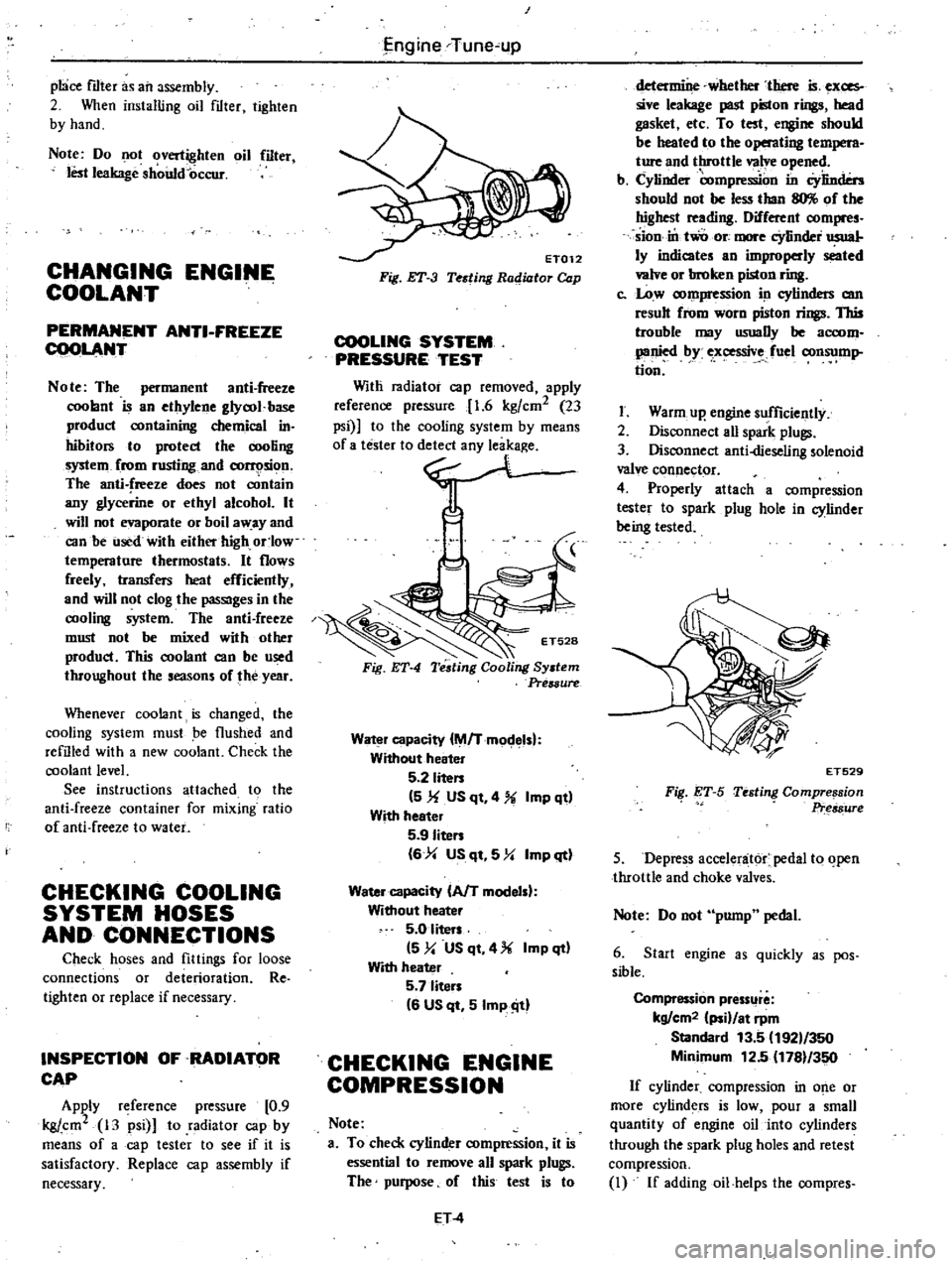
ET012
Fig
ET
3
Testing
Radiator
Cap
COOLING
SYSTEM
PRESSURE
TEST
Witli
radiator
cap
removed
apply
reference
pressure
1
6
kgfcm2
23
psi
to
the
cooling
system
by
means
0
no
Fig
ET
4
Water
capacity
M
Tmodelsl
Without
heater
5
2
liten
5
1f
US
qt
4
Imp
qt
With
heeter
5
9
Iiten
6
4
US
qt
5
Y
Imp
qt
Water
capacity
AfT
modelsl
Without
heater
5
0
liters
5
y
US
qt
4
Imp
qt
With
heater
5
7
liten
6
US
qt
5
Imp
ill
CHECKING
ENGINE
COMPRESSION
Note
a
To
check
cylinder
compression
it
is
essential
to
remove
all
spark
plugs
The
purpose
of
this
test
is
to
ET
4
determine
whether
there
is
exces
sive
leakage
past
piston
rings
head
gasket
etc
To
test
engine
should
be
heated
to
the
operating
t
M
ture
and
throttle
valve
opened
b
Cylinder
compre
on
in
Cylinders
should
not
be
less
than
llO
of
the
highest
reading
Different
compres
sion
in
two
ore
more
cYlinder
usual
ly
indicates
an
improperly
seated
valve
or
broken
piston
ring
c
Low
compression
in
cylinders
am
result
from
worn
piston
rings
This
trouble
may
usuaDy
be
accom
panied
by
ex
ssive
fuel
consump
tion
I
Warm
up
engine
sufficiently
2
Disconnect
aU
spark
plugs
3
Disconnect
anti
dieseling
solenoid
valve
connector
4
Properly
attach
a
compression
tester
to
spark
plug
hole
in
cylinder
being
tested
FiI
ET
S
ET529
Testing
Compre
sion
Pr
s8ure
5
Depress
accelenit6r
pedal
to
open
throttle
and
choke
valves
Note
Do
not
pump
pedal
6
Start
engine
as
quickly
as
pos
sible
Compression
pressllre
kg
cm2
ii
at
rpm
Standard
13
5
192
350
Minimum
12
5
1781
350
If
cylinder
compression
in
o
e
or
more
cylinders
is
low
pour
a
small
quantity
of
engine
oil
into
cylinders
through
the
spark
plug
holes
and
retest
compression
I
If
addingoil
helps
the
compres
Page 20 of 548
SO
B
T
D
C
l650
rpm
Non
California
models
except
Canada
100
B
T
D
C
650
rpm
Canada
models
Note
On
FU
models
ignition
timing
is
set
under
a
condition
where
distributor
vacuum
hose
is
discon
nected
If
necessary
adjust
ignition
timing
as
follows
I
Loosen
set
screw
until
dis
tributor
c
uJ
be
moved
by
hand
2
Adjust
ignition
timing
to
speci
fications
3
Lock
distributor
set
screw
and
make
sure
that
timing
is
correct
YJ
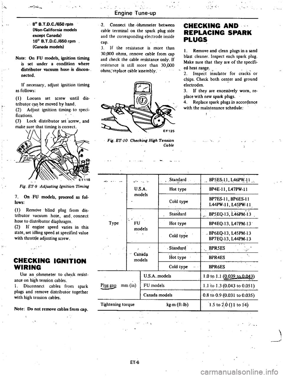
Fig
T
9
Adjusting
Ignition
Timing
7
On
FU
models
proceed
as
fol
lows
I
Remove
blind
plug
from
dis
tributor
vacuum
hose
and
connect
hose
to
distributor
diaphragm
2
If
engine
speed
varies
in
this
state
set
idling
speed
at
specified
value
with
throttle
adjusting
screw
CHECKING
IGNITION
WIRING
Use
an
ohmmeter
to
check
resist
ance
on
high
tension
cables
1
Disconnect
cables
from
spark
plugs
and
remove
distributor
together
with
high
tension
cables
Note
Do
not
remove
cables
from
cap
Engine
Tune
up
2
Connect
the
ohmmeter
between
cable
terminal
on
the
spark
plug
side
and
the
corresponding
electrode
inside
cap
3
If
the
resistance
is
more
than
30
000
ohms
remove
cable
from
cap
and
check
the
cable
resistance
only
If
resistance
is
still
more
than
30
000
ohms
replace
c3ble
assembly
Fig
ET
IO
Checking
High
Tension
Cable
u
s
A
models
Type
FU
models
Standard
Hot
type
Cold
type
U
S
A
models
Canada
models
r
1g
mm
in
FU
models
Canada
models
Tightening
torque
kg
m
ft
lb
ET
6
Stan
rd
Hot
type
Cold
type
S
aridard
Hot
type
Cold
type
CHECKING
AND
REPLACING
SPARK
PLUGS
I
Remove
and
clean
plugs
in
a
sand
blast
cleaner
Inspect
each
spark
plug
Make
sure
that
they
are
of
the
specifi
ed
heat
range
2
Inspect
insulator
for
cracks
or
chips
Check
both
center
and
ground
electrodes
3
If
they
are
excessively
worn
re
place
with
new
spark
plugs
4
Replace
spark
plugs
in
accordance
with
the
maintenance
schedule
BP
ES
ll
L46PW
l
BP4E
ll
L47PW
ll
BP7ES
ll
BP6ES
ll
L44PW
II
L4
PW
11
BP5
EQ
13
L46PM
13
BP4EQ
13
L47PM
13
BP6EQ
13
L45PM
13
BP7EQ
13
L44PM
13
BPR5ES
BPR4ES
BPR6ES
1
0
to
1
1
LQ39
to
0
043
l
l
to
1
3
0
043
to
0
051
0
8
to
0
9
0
031
to
0
035
1
5
to
i
6
P
to
14
Page 33 of 548
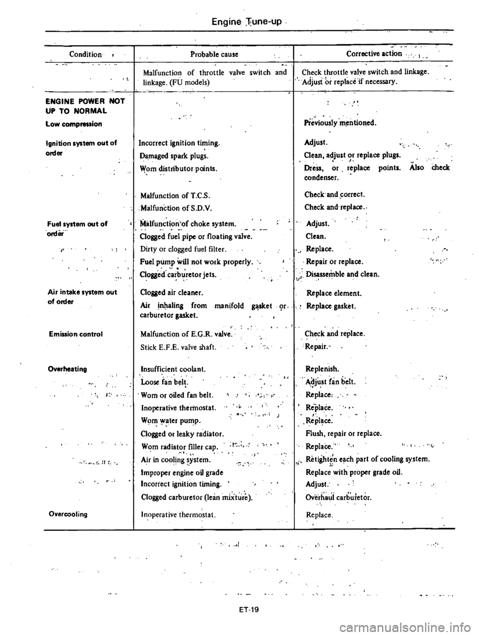
Condition
ENGINE
POWER
NOT
UP
TO
NORMAL
Low
compmsion
Ignition
system
out
of
order
Fuel
system
out
of
order
Air
intake
system
out
of
order
Emission
control
Overheating
J
f
H
r
Overcooling
Engine
liune
up
Probable
cause
Malfunction
of
throttle
valve
switch
and
linkage
FU
models
Incorrect
ignition
timing
Damaged
spark
plugs
Wom
distributor
points
Malfunction
of
T
C
S
cMalfunction
of
S
D
V
Milfunction
of
choke
system
Clogged
fuel
pipe
or
floating
valve
Dirty
or
clogged
fuel
filter
Fuel
pump
will
not
work
properly
Clogged
carb
retor
jets
Clogged
air
cleaner
Air
aling
from
manifold
g
sket
r
carburetor
gasket
Malfunction
of
E
G
R
valve
Stick
E
F
E
valve
shaft
Insufficient
coolant
Loose
fan
bel
Wom
or
oiled
fan
belt
Inoperative
therinostat
Wom
ater
pu
p
Clogged
or
leaky
radiator
Wom
radiator
filler
ca
Air
in
cooling
ystein
Improper
engine
oil
grade
Incorrect
ignition
timing
Clogged
carburetor
lean
miiture
Inoperative
thermostat
1
ET
19
Corrective
action
Check
throttle
valve
switch
and
linkage
Adjusi
i
r
replace
if
necessary
Previously
m
entioned
Adjust
Clean
adjust
or
replace
plugs
Dress
or
replace
points
Also
check
condenser
Check
and
correct
Check
and
replace
Adjust
Clean
Replace
Repair
or
replace
t
J
Disassemble
and
clean
Replace
element
Replace
gasket
Check
and
replace
Repair
Replenish
Adjust
fan
belt
Replace
Replace
Repl
ce
Flush
repair
or
replace
ReplaCe
Retightin
e
ch
part
of
cooling
system
Replace
with
proper
grade
oil
Adjust
Overhaui
carburetor
Replace
Page 35 of 548
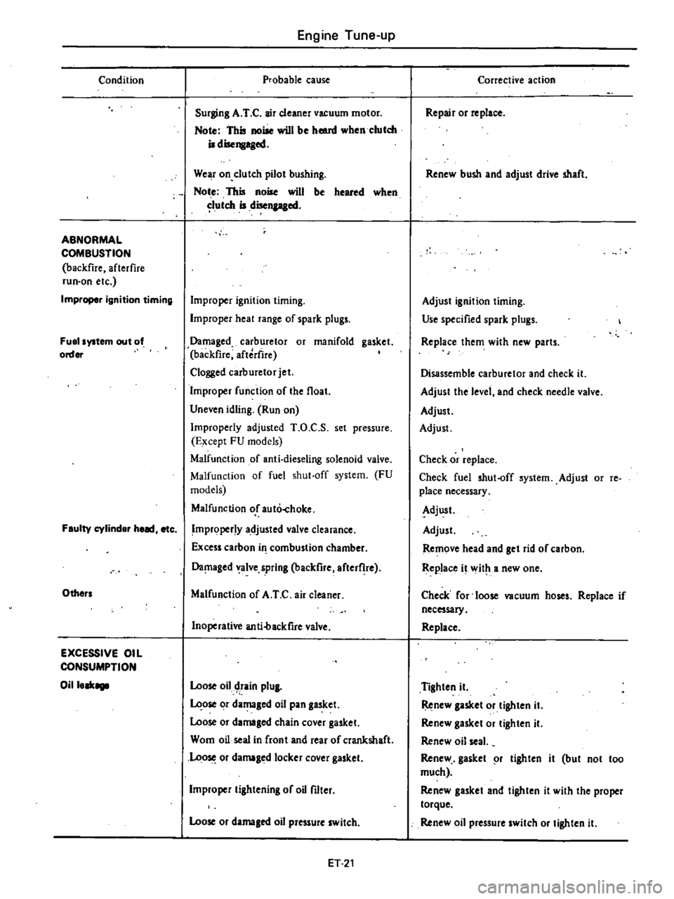
Condition
ABNORMAL
COMBUSTION
backfire
afterfire
run
on
etc
Improper
ignition
timing
Fuel
system
out
of
order
Feulty
cylinder
heed
etc
Others
EXCESSIVE
OIL
CONSUMPTION
Oilleek8111
Engine
Tune
up
Probable
cause
Surging
A
T
C
air
cleaner
vacuum
motor
Note
This
noise
will
be
hmnl
when
clutch
iI
disengaged
We
r
on
clutch
pilot
bushing
Not
e
This
noise
will
be
heared
when
utch
iI
disengaged
Improper
ignition
timing
Improper
heal
range
of
spark
plugs
Damaged
carburetor
or
manifold
gasket
backfire
aftedire
Clogged
carburetor
jet
Improper
function
of
the
float
Uneven
idling
Run
on
Improperly
adjusted
T
O
C
S
set
pressure
Except
FU
models
Malfunction
of
anti
dieseling
solenoid
valve
Malfunction
of
fuel
shut
off
system
FU
models
Malfunction
or
auto
hoke
Improper
y
adjusted
valve
clearance
Excess
carbon
in
combustion
chamber
Da
laged
alve
spring
backfire
after
he
Malfunction
of
A
T
C
air
cleaner
Inoperative
anti4lackfire
valve
Loose
oil
tain
plUI
ose
or
damaged
oil
pan
gasket
Loose
or
damaled
chain
cover
gasket
Wom
oil
seal
in
front
and
rear
of
crankshaft
Loo
or
damaged
locker
cover
gasket
Improper
lilhtening
of
oU
filter
Loose
or
damaled
oil
pressure
switch
ET
21
Corrective
action
Repair
or
replace
Renew
bush
and
adjust
drive
shaft
Adjust
ignition
liming
Use
specified
spark
plugs
Replace
them
with
new
parts
Disassemble
carburetor
and
check
it
Adjust
the
level
and
check
needle
valve
Adjust
Adjust
Check
or
replace
Check
fuel
shut
off
system
Adjust
or
re
place
necessary
Adjust
Adjust
Remove
head
and
get
rid
of
carbon
Replace
it
wit
a
new
one
Check
for
loose
vacuum
hoses
Replace
if
necessary
Replace
Tighten
it
Renew
lasket
or
tighten
iI
Renew
gasket
or
lighten
it
Renew
oil
seal
Renew
gasket
r
lighten
it
but
not
too
much
Renew
gasket
and
tighten
it
with
the
proper
torque
Renew
oil
pressure
switch
or
tighten
it
Page 178 of 548
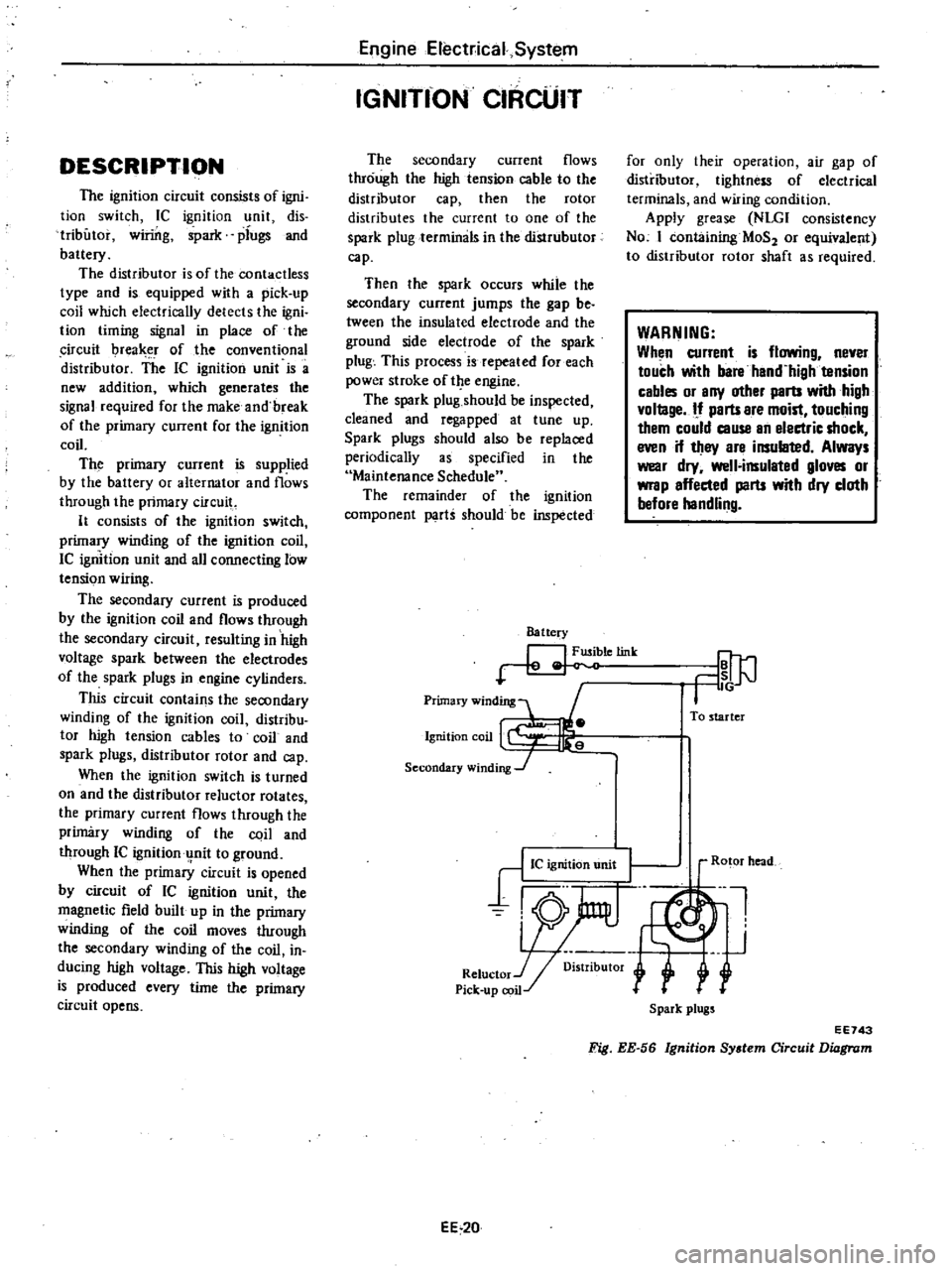
DESCRIPTION
The
ignition
circuit
consists
of
igni
tion
switch
Ie
ignition
unit
dis
tributor
winng
ipark
plugs
and
battery
The
distributor
is
of
the
contactless
type
and
is
equipped
with
a
pick
up
coil
which
electrically
detects
the
igni
tion
timing
signal
in
place
of
the
ircuit
I
rea
r
of
the
conventional
distributor
The
IC
ignition
unit
is
a
new
addition
which
generates
the
signal
required
for
the
make
and
break
of
the
primary
current
for
the
ignition
coil
The
primary
current
is
supplied
by
the
battery
or
alternator
and
flows
through
the
primary
circuit
It
consists
of
the
ignition
switch
primary
winding
of
the
ignition
coil
IC
ignition
unit
and
all
connecting
low
tension
wiring
The
secondary
current
is
produced
by
the
ignition
coil
and
flows
through
the
secondary
circuit
resulting
in
high
voltage
spark
between
the
electrodes
of
the
spark
plugs
in
engine
cylinders
This
circuit
contains
the
secondary
winding
of
the
ignition
coil
distribu
tor
high
tension
cables
to
coil
and
spark
plugs
distributor
rotor
and
cap
When
the
ignition
switch
is
turned
on
and
the
distributor
reluctor
rotates
the
primary
current
flows
through
the
primary
winding
of
the
coil
and
through
IC
ignitionu
nit
to
ground
When
the
primary
circuit
is
opened
by
circuit
of
IC
ignition
unit
the
magnetic
field
built
up
in
the
primary
winding
of
the
coil
moves
through
the
secondary
winding
of
the
coil
in
ducing
high
voltage
This
high
voltage
is
produced
every
time
the
primary
circuit
opens
EngineElect
ical
System
IGNITfON
CIRCUIT
The
secondary
current
flows
through
the
high
tension
cable
to
the
distributor
cap
then
the
rotor
distributes
the
current
to
one
of
the
spark
plug
terminals
in
the
distrubutor
cap
Then
the
spark
occurs
while
the
secondary
current
jumps
the
gap
be
tween
the
insulated
electrode
and
the
ground
side
electrode
of
the
spark
plug
This
process
is
repeated
for
each
power
stroke
of
t
e
engine
The
spark
plug
should
be
inspected
cleaned
and
regapped
at
tune
up
Spark
plugs
should
also
be
replaced
periodically
as
specified
in
the
Maintenance
Schedule
The
remainder
of
the
ignition
component
parti
should
be
inspected
Battery
letink
Primary
winding
1
Ignition
coil
Secondary
winding
J
for
only
their
operation
air
gap
of
distributor
tightness
of
electrical
terminals
and
wiring
condition
Apply
grease
NLGI
consistency
No
I
containing
MaS
or
equivalent
to
distributor
rotor
shaft
as
required
WARNING
When
current
is
flowing
never
touch
with
bare
hand
high
tension
cables
or
any
other
parts
with
high
vollage
If
parts
are
moist
touching
them
could
cause
an
electric
shock
even
if
they
are
insulated
Always
wear
dry
well
insulated
gloves
or
wrap
affected
parts
with
dry
cloth
before
handling
To
starter
EE
20
Ro
or
head
Ul
J
r
Spark
plugs
EE743
Fig
EE
56
Ignition
System
Circuit
Diagram
Page 186 of 548

JUDGMENT
OV
is
indicated
IC
ignition
unit
NG
But
condition
of
pick
up
coil
can
not
be
judged
Proceed
to
the
item
for
Pick
up
Coil
Check
Bat
tery
voltage
is
indicated
Condition
cannot
be
judged
Proceed
to
item
9
9
Remove
IC
ignition
unit
Refer
to
IC
ignition
Unit
for
re
moval
10
Measure
resistance
between
two
terminals
of
pick
up
coil
JUDGMENT
Approx
40011
are
indicated
The
ignition
coil
is
an
oil
filled
type
The
ignition
coil
case
is
filled
with
oil
which
has
good
insulating
and
heat
radiating
characteristics
The
ignition
coil
has
a
greater
ratio
between
the
primary
and
secondary
windings
to
step
up
battery
voltage
to
high
voltage
This
causes
stronger
sparks
to
jump
the
spark
plug
gap
The
cap
is
made
of
alkyd
resin
which
offers
high
resistance
to
electric
arc
and
increased
insulation
When
high
tension
cable
is
installed
to
ignition
coil
there
should
be
no
clearance
between
their
caps
Note
Do
not
disconnect
high
tension
cables
from
spark
plugs
during
en
gine
running
r
EE354
1
High
tension
cable
2
Rubber
cap
Fig
EE
74
Correct
Instalhltion
of
High
Tension
Cable
Engine
Electrical
System
Pick
up
coil
OK
IC
ignition
unit
NG
Approx
40011
are
not
indicated
Pick
up
coil
NG
Condition
of
IC
ignition
unit
can
not
be
judged
Proceed
to
item
11
II
Replace
faulty
pick
up
coil
with
new
one
12
Install
original
IC
ignition
unit
13
Check
parking
performance
JUDGMENT
Sparks
occur
IC
ignition
system
IC
ignition
unit
OK
No
spark
OCCUrs
IC
ignition
unit
NG
IGNITION
COIL
If
NG
replace
faulty
IC
ignition
unit
with
new
one
P1ck
up
coil
check
I
Make
sure
that
ignition
switch
is
in
OFF
position
2
Remove
IC
ignition
unit
Refer
to
IC
Ignition
Unit
for
removal
3
Measure
resistance
between
two
terminals
of
pick
up
coil
JUDGMENT
Approx
40011
are
indicated
OK
Approx
40011
are
not
indicated
NG
If
NG
replace
faulty
pick
up
coil
with
new
one
1
@
I
rJ
1
C
I
I
i
jllll
1
t
1
Rubber
cap
for
ignition
coil
2
Secondary
tenninal
3
Cap
4
Primary
terminal
5
Spring
6
Secondary
winding
EE
28
EE578
7
Primary
winding
8
Side
core
9
Insulator
10
Center
core
11
Segment
12
Case
Fig
EE
75
Ignition
Coit
Page 187 of 548
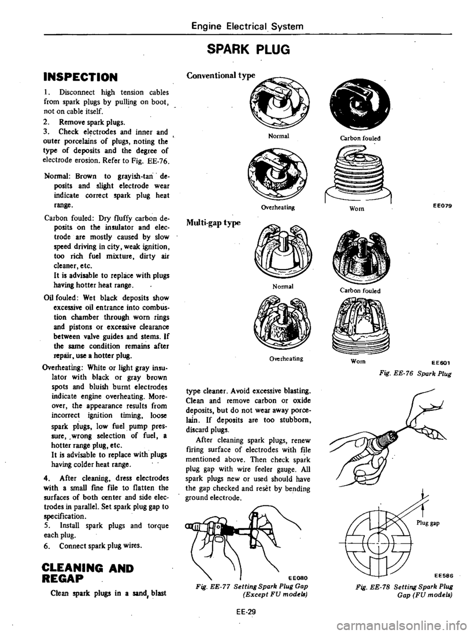
INSPECTION
I
Disconnect
high
tension
cables
from
spark
plugs
by
pulling
on
boot
not
on
cable
itself
2
Remove
spark
plugs
3
Check
electrodes
and
inner
and
outer
porcelains
of
plugs
noting
the
type
of
deposits
and
the
degree
of
electrode
erosion
Refer
to
Fig
EE
76
Normal
Brown
to
grayish
Ian
de
posits
and
slighl
electrode
wear
indicate
correct
spark
plug
heat
range
Carbon
fouled
Dry
fluffy
carbon
de
posits
on
the
insulator
and
elec
trode
are
mostly
caused
by
slow
speed
driving
in
city
weak
ignition
too
rich
fuel
mixture
dirty
air
cleaner
etc
H
is
advisable
to
replace
with
plugs
having
hotter
heat
range
Oil
fouled
Wet
black
deposits
show
excessive
oil
entrance
into
comb
us
tion
chamber
through
worn
rings
and
pistons
or
excessive
clearance
between
valve
guides
and
stems
If
the
same
condition
remains
after
repair
use
a
hotter
plug
Overheating
White
or
light
gray
insu
lator
with
black
or
gray
brown
spots
and
bluish
burnt
electrodes
indicate
engine
overheating
More
over
the
appearance
results
from
incorrect
ignition
timing
loose
spark
plugs
low
fuel
pump
pres
sure
wrong
selection
of
fuel
a
hotter
range
plug
etc
H
is
advisable
to
replace
with
plugs
having
colder
heat
range
4
After
cleaning
dress
electrodes
with
a
smaU
fme
file
to
flatten
the
surfaces
of
both
center
and
side
elec
trodes
in
parallel
Set
spark
plug
gap
to
specification
5
Install
spark
plugs
and
torque
each
plug
6
Connect
spark
plug
wires
CLEANING
AND
REGAP
Clean
spark
plugs
in
a
sand
blast
Engine
Electrical
System
SPARK
PLUG
Conventional
type
Normal
Overheating
Multi
gap
type
Nonnal
Overheating
type
cleaner
Avoid
excessive
blasting
Clean
and
remove
carbon
or
oxide
deposits
but
do
not
wear
away
porce
lain
If
deposits
are
too
stubborn
discard
plugs
After
cleaning
spark
plugs
renew
firing
surface
of
electrodes
with
file
mentioned
above
Then
check
spark
plug
gap
with
wire
feeler
gauge
All
spark
plugs
new
or
used
should
have
the
gap
checked
and
reset
by
bending
ground
electrode
EEOSO
Fig
EE
77
Setting
Spark
Plug
Gap
Except
FU
model
EE
29
Carbon
fouled
EE079
Worn
Carbon
fouled
Worn
EE601
Fig
EE
76
Spark
Plug
EE586
Fig
EE
78
Setting
Spark
Plug
Gap
FU
models
Page 195 of 548

Engine
Electrical
System
IV
IGNITION
CIRCUIT
When
engine
does
not
start
If
there
is
no
problem
in
fuel
system
ignition
system
should
be
checked
This
can
be
easily
done
by
detaching
a
high
tension
cable
from
distributor
starting
engine
and
ob
serving
oondition
of
spark
that
occurs
between
high
tension
cable
and
engine
block
After
checking
this
repair
as
necessary
tery
and
anti
dieseliilg
wlenoid
valve
connector
to
cuI
off
supply
of
fuel
10
engine
Then
observe
the
condition
of
sparks
while
starter
motor
is
in
operation
Note
Turn
ignilion
switch
off
and
disconnect
ground
cable
from
bat
Condition
Location
Probable
cause
Corrective
action
No
spark
at
all
Distributor
Breakage
of
lead
wire
on
low
tension
side
Repair
Poor
insulation
of
cap
and
rotor
head
Replace
Open
pick
up
coil
Replace
Air
gap
wider
than
specification
Adjust
Ignition
coil
Wire
breakage
or
short
circuit
of
coil
Replace
with
new
one
High
tension
cable
Wire
coming
off
Repair
Faulty
insulation
Replace
IC
ignition
unit
Faulty
IC
ignition
unit
Replace
Breakage
of
circuit
Replace
Detached
connection
Repair
Spark
length
Spark
plugs
Spark
plug
gap
too
wide
Correct
or
replace
More
than
6
mm
Too
much
carbon
Clean
or
replace
0
24
in
Broken
neck
of
insulator
Replace
Expiration
of
plug
life
Replace
Distributor
Air
gap
too
wide
Correct
IC
ignition
unit
Faulty
IC
ignition
unit
Replace
Breakage
of
circuit
Replace
Detached
connection
Repair
EE
37
Page 196 of 548

2
Engine
rotates
but
does
not
run
smoothly
This
may
be
caused
by
the
ignition
Condition
Location
Engine
misses
Distributor
Ignition
coil
High
tension
cable
Spark
plugs
IC
ignition
unit
Engine
causes
knocking
very
often
Distributor
Spark
plugs
Engine
does
not
deliver
enough
power
Distributor
Spark
plugs
Engine
Electrical
System
system
or
other
engine
conditions
not
related
to
ignition
system
Therefore
first
complete
inspection
of
ignition
system
should
be
carried
out
Probable
cause
Foreign
matter
onpicl
up
coil
Improper
air
gap
Leak
of
electricity
at
cap
and
rotor
head
Breakage
of
pick
up
coil
lead
wire
Worn
or
shaky
breaker
plate
Worn
or
shaky
distributor
driVing
shaft
Layer
short
circuit
or
inferior
quality
coil
Deterioration
of
insulation
with
cense
quenlleak
of
electricity
Fouled
Leak
of
electricity
at
upper
porcelain
insulator
Spark
plug
gap
too
narrow
Faulty
IC
ignition
unit
Breakage
of
circuit
Detached
connection
Improper
ignition
timing
too
advanced
Coming
off
or
breakage
of
governor
spring
Worn
pin
or
hole
of
governor
Burnt
too
much
Improper
ignition
timing
too
retarded
Improper
functioning
governor
Foreign
particles
stuck
in
air
gap
Fouled
EE
38
Corrective
action
Clean
Correct
Repair
or
replace
Replace
Replace
assembly
Replace
aSsembly
Replace
with
good
one
Replace
Clean
Repair
or
replace
Correct
or
replace
Replace
Replace
Repair
Correct
Correct
or
replace
Replace
Replace
Correct
Replace
assembly
Clean
Clean