adding oil DATSUN 210 1979 Service Manual
[x] Cancel search | Manufacturer: DATSUN, Model Year: 1979, Model line: 210, Model: DATSUN 210 1979Pages: 548, PDF Size: 28.66 MB
Page 18 of 548

pl
ice
mter
as
an
assembly
2
When
installing
oil
mter
tighten
by
hand
Note
Do
not
overtighten
oil
filter
lest
leakage
shoUld
occur
CHANGING
ENGINE
COOLANT
PERMANENT
ANTI
FREEZE
COOLANT
Note
The
permanent
anti
freeze
coolant
is
an
ethylene
glya
l
base
product
containing
chemical
in
hibitors
to
protect
the
cooling
system
from
rusting
and
corrosion
The
anti
freeze
does
not
cOntain
any
glycerine
or
ethyl
alcohol
It
will
not
evaporate
or
boil
a
ay
and
can
be
ilsed
with
either
high
or
low
temperature
thermostats
It
flows
freely
transfers
heat
efficiently
and
will
not
clog
the
passages
in
the
cooling
system
The
anti
freeze
must
not
be
mixed
with
other
product
This
coolant
can
be
used
throughout
the
seasons
of
the
year
Whenever
coolant
is
changed
the
cooling
system
must
be
flushed
and
refilled
with
a
new
coolant
Check
the
coolant
level
See
instructions
attached
to
the
anti
freeze
container
for
mixing
ratio
of
anti
freeze
to
water
CHECKING
COOLING
SYSTEM
HOSES
AND
CONNECTIONS
Check
hoses
and
fittings
for
loose
connections
or
deterioration
Re
tighten
or
replace
if
necessary
INSPECTION
OF
RADIATOR
CAP
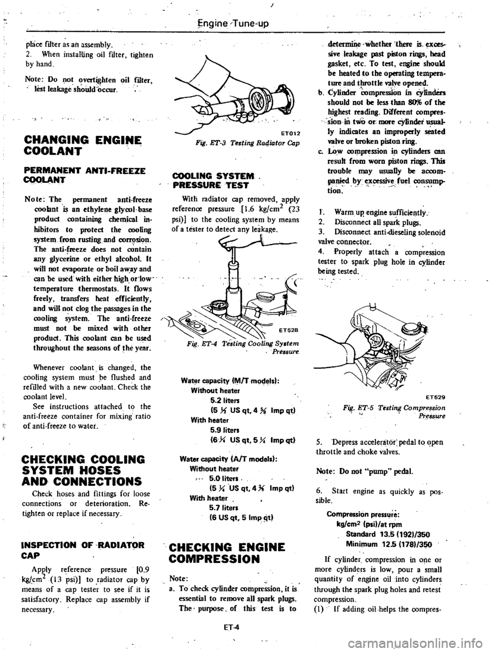
Apply
reference
pressure
0
9
kgj
cm2
13
psi
to
radiator
cap
by
means
of
a
cap
tester
to
see
if
it
is
satisfactory
Replace
cap
assembly
if
necessary
I
j
ngine
Tune
up
ET012
Fig
ET
3
Testing
Radiator
Cap
COOLING
SYSTEM
PRESSURE
TEST
Witli
radiator
cap
removed
apply
reference
pressure
1
6
kgfcm2
23
psi
to
the
cooling
system
by
means
0
no
Fig
ET
4
Water
capacity
M
Tmodelsl
Without
heater
5
2
liten
5
1f
US
qt
4
Imp
qt
With
heeter
5
9
Iiten
6
4
US
qt
5
Y
Imp
qt
Water
capacity
AfT
modelsl
Without
heater
5
0
liters
5
y
US
qt
4
Imp
qt
With
heater
5
7
liten
6
US
qt
5
Imp
ill
CHECKING
ENGINE
COMPRESSION
Note
a
To
check
cylinder
compression
it
is
essential
to
remove
all
spark
plugs
The
purpose
of
this
test
is
to
ET
4
determine
whether
there
is
exces
sive
leakage
past
piston
rings
head
gasket
etc
To
test
engine
should
be
heated
to
the
operating
t
M
ture
and
throttle
valve
opened
b
Cylinder
compre
on
in
Cylinders
should
not
be
less
than
llO
of
the
highest
reading
Different
compres
sion
in
two
ore
more
cYlinder
usual
ly
indicates
an
improperly
seated
valve
or
broken
piston
ring
c
Low
compression
in
cylinders
am
result
from
worn
piston
rings
This
trouble
may
usuaDy
be
accom
panied
by
ex
ssive
fuel
consump
tion
I
Warm
up
engine
sufficiently
2
Disconnect
aU
spark
plugs
3
Disconnect
anti
dieseling
solenoid
valve
connector
4
Properly
attach
a
compression
tester
to
spark
plug
hole
in
cylinder
being
tested
FiI
ET
S
ET529
Testing
Compre
sion
Pr
s8ure
5
Depress
accelenit6r
pedal
to
open
throttle
and
choke
valves
Note
Do
not
pump
pedal
6
Start
engine
as
quickly
as
pos
sible
Compression
pressllre
kg
cm2
ii
at
rpm
Standard
13
5
192
350
Minimum
12
5
1781
350
If
cylinder
compression
in
o
e
or
more
cylinders
is
low
pour
a
small
quantity
of
engine
oil
into
cylinders
through
the
spark
plug
holes
and
retest
compression
I
If
addingoil
helps
the
compres
Page 19 of 548

sion
pressure
chances
are
that
piston
rings
are
worn
or
damaged
2
If
pressure
stays
low
the
likeli
hood
is
that
valve
is
sticking
or
seating
Engine
Tune
up
improperly
3
If
cylinder
compression
in
any
two
adjacent
cylinders
is
low
and
if
adding
oil
does
not
help
the
compres
sion
there
is
leakage
past
the
gasketed
surface
Oil
and
water
in
combustion
cham
bers
can
result
from
this
problem
IGNITION
AND
FUEL
SYSTEM
CHECKING
BATTERY
I
Remove
six
vent
plugs
and
check
electrolyte
level
in
each
battery
cell
If
necessary
pour
distilled
water
Overflow
Correct
Shortage
t
t
j
t
t
t
EE358
Fig
ET
6
Checking
Electrolyte
Level
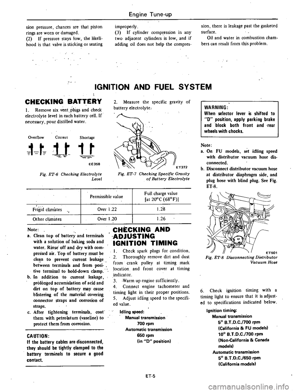
2
Measure
the
specific
gravity
of
battery
electrolyte
E
T372
Fig
ET
7
Checking
Specific
Gravity
of
Battery
Electrolyte
Over
1
22
Full
charge
value
at
200C
680F
1
28
1
26
Permissible
value
Frigid
climates
Other
climates
Note
a
Clean
top
of
battery
and
terminals
with
a
solution
of
baking
soda
and
water
Rinse
off
and
dry
with
com
pressed
air
Top
of
battery
must
be
c1
n
to
prevent
current
leakage
between
terminals
and
from
posi
tive
terminal
to
hold
down
clamp
b
In
addition
to
current
leakage
prolonged
accumulation
of
acid
and
dirt
on
top
of
hattery
may
cause
blistering
of
the
material
covering
ronnector
straps
and
rorrosion
of
straps
c
Afte
r
tightening
terminals
coat
them
with
petrolatum
vaseline
to
protect
them
from
corrosion
CAUTION
If
the
battery
cables
are
disconnected
they
should
be
tightly
clamped
to
the
battery
terminals
to
secure
a
good
contact
Over
I
20
CHECKING
AND
ADJUSTING
IGNITION
TIMING
Check
spark
plugs
for
condition
2
Thoroughly
remove
dirt
and
dust
from
crank
pulley
at
timing
mark
location
and
front
cover
at
timing
indicator
3
Warm
up
engine
sufficiently
4
Connect
engine
tachometer
and
timing
light
in
their
proper
positions
5
Adjust
idling
speed
to
the
specifi
ed
value
Idling
speed
Manual
transmission
700
pm
Automatic
transmission
6S0
rpm
in
0
position
ET
S
WARNING
When
selector
lever
is
shifted
to
0
position
apply
parking
brake
and
block
both
front
and
rear
wheels
with
chocks
Note
a
On
FU
models
set
idling
speed
with
distributor
vacuum
hose
dis
connected
b
Disconnect
distributor
vacuum
hose
at
distributor
diaphragm
side
and
plug
hose
with
blind
plug
See
Fig
ET
8
ET501
Fig
ET
B
Disconnecting
Distributor
Vacuum
Hose
6
Check
ignition
timing
with
a
timing
light
to
ensure
that
it
is
adjust
ed
to
specifications
indicated
below
Ignition
timing
Manual
transmission
SO
B
T
0
C
f700
rpm
California
FU
models
100
B
T
0
C
f700
pm
Non
California
Canada
models
Automatic
transmission
SO
B
T
0
C
f6S0
rpm
California
models
Page 167 of 548

Starting
motor
S
DIAGNOSES
OF
TEST
I
Low
speed
with
no
load
and
high
current
draw
may
result
from
the
following
I
Tight
dirty
or
worn
bearings
2
Bent
armature
shaft
or
loosened
field
probe
3
Shorted
armature
Check
armature
further
4
A
grounded
armature
or
field
a
Remove
input
terminal
b
Raise
two
negative
side
brushes
from
commutator
c
Using
a
circuit
tester
place
one
probe
onto
input
terminal
and
the
other
onto
yoke
d
If
tester
indicates
continuity
raise
the
other
two
brushes
and
check
field
and
armature
separately
to
deter
mine
whether
field
or
armature
is
grounded
2
Failure
to
operate
with
high
cur
rent
draw
may
be
caused
by
the
following
I
A
grounded
or
open
field
coil
Inspect
the
connection
and
trace
circuit
with
a
circuit
tester
2
Armature
coil
does
not
operate
Inspect
commutator
for
excessive
burning
In
this
case
arc
may
occur
on
damaged
commutator
when
motor
is
operated
with
no
load
3
Burned
out
commutator
bar
Weak
brush
spring
tension
broken
Engine
Electrical
System
Switch
Battery
Vultmeter
Ammeter
EE738
Fig
EE
22
No
load
Testing
brush
spring
rubber
bush
thrust
out
of
mica
in
commuta
tor
or
a
loose
contact
between
brush
and
conunuta
tor
would
cause
commutator
bar
to
burn
3
Low
current
draw
and
low
no
load
speed
would
cause
high
internal
resistance
due
to
loose
connections
damaged
leads
dirty
commutator
and
causes
listed
on
item
2
3
MAGNETIC
SWITCH
ASSEMBLY
TEST
Switch
2
1
6
11
p
IB
b
I
Battery
Starter
motor
EE351
Fig
EE
23
Circuit
of
Magnetic
Switch
Assembly
Test
If
the
starting
motor
check
is
OK
check
magnetic
switch
assem
bly
Connect
cables
between
negative
battery
terminal
and
start
ing
motor
M
terminal
positive
battery
terminal
and
starting
motor
8
terminal
connecting
a
switch
in
series
as
shown
above
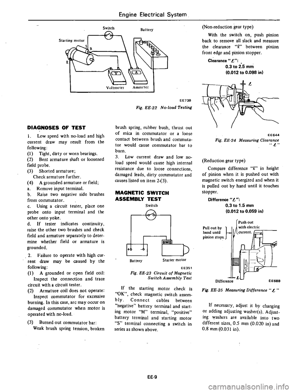
EE
9
Non
reduction
gear
type
With
the
switch
on
push
pinion
back
to
remove
all
slack
and
measure
the
clearance
between
pinion
front
edge
and
pinion
stopper
Clearance
L
0
3
to
2
5
mm
0
012
to
0
098
in
EE644
Fig
EE
24
Measuring
Clearance
l
Reduction
gear
type
Compare
difference
2
in
height
of
pinion
when
it
is
pushed
out
with
magnetic
switch
energized
and
when
it
is
pulled
out
by
hand
until
it
touches
stopper
Difference
L
0
3
to
1
5
mm
0
012
to
0
059
in
Pull
out
by
hand
until
pinion
stops
Push
out
1
1
n
11
r
L
Difference
EE688
Fig
EE
25
Measuri
g
Difference
L
If
necessary
adjust
it
by
changing
or
adding
adjusting
washer
s
Adjust
ing
washers
are
available
into
two
different
sizes
0
5
mm
0
020
in
and
0
8
mm
0
031
in