change time DATSUN 210 1979 Service Manual
[x] Cancel search | Manufacturer: DATSUN, Model Year: 1979, Model line: 210, Model: DATSUN 210 1979Pages: 548, PDF Size: 28.66 MB
Page 49 of 548
PRECAUTION
Before
assembling
engine
observe
following
precautions
I
Clean
all
disass
mbled
parts
with
clean
solvent
All
611
holes
in
crank
shaft
camshaft
valve
rocker
shaft
etc
should
be
thoroughly
cleaned
to
re
move
all
traces
of
grinding
chips
or
lint
Always
use
clean
solvent
2
In
general
used
gaskets
packings
and
oil
seals
should
be
replaced
3
Under
no
circumstances
should
lockwashers
be
reuse
d
4
Place
bolts
nuts
and
woshers
back
in
their
original
parts
or
from
which
they
were
removed
5
MOst
packing
Serve
best
when
liquid
packing
is
applied
to
sealing
surfaces
When
desigiiated
use
suitable
liquid
packing
to
eliminate
possibility
of
water
oil
and
gas
leak
6
Prior
to
assemQling
all
sliding
surfaces
should
be
lioerally
oiled
7
Proper
tightening
is
essential
to
successful
performanCe
of
all
car
re
pairs
It
is
also
important
to
follow
correct
tightenig
sequence
in
pulling
up
cylinder
head
Be
on
alert
at
all
times
to
amount
of
clearance
per
mitted
8
Cleanliness
of
tools
or
parts
such
as
work
bench
used
jn
making
a
repai
is
essential
When
setting
up
a
job
every
precaution
should
be
taken
that
tools
or
parts
are
free
of
dirt
mud
and
oil
Do
not
work
in
dust
and
grit
for
they
are
primary
cause
of
wear
in
any
engine
CYLINDER
HEAD
I
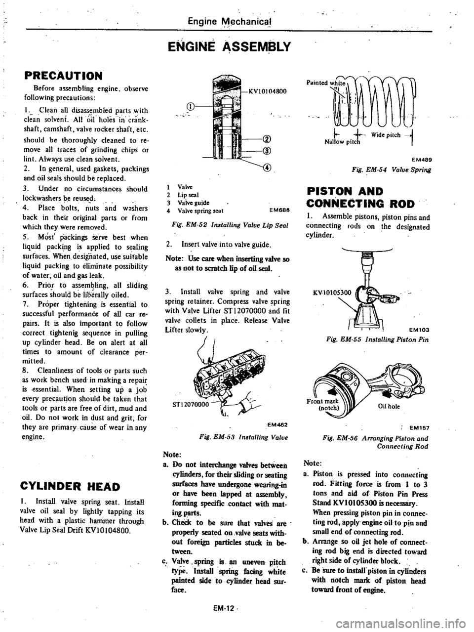
Install
valve
spring
seat
Install
valve
oil
seal
by
lightly
tapping
its
head
with
a
plastic
hammer
through
Valve
Lip
Seal
Drift
KVI0104800
Engine
Mechanical
ENGINE
ASSEMBLY
m
f
if
@
@
4
1
Valve
2
Lip
seal
3
Valve
guide
4
Valve
spring
seat
EM688
Fig
EM
52
tailing
Valve
Lip
Seal
2
Insert
valve
into
valve
guide
Note
Use
care
when
inserting
valve
so
as
not
to
scratch
lip
of
oil
seal
3
Install
valve
spring
and
valve
spring
retainer
Compress
valve
pring
with
Valve
Lifter
STl2070000
and
fit
valve
collets
in
place
Release
Valve
Lifter
slowly
EM462
Fig
EM
53
Inatalling
Valve
Note
8
Do
not
interchange
valves
between
cylinders
for
their
sliding
or
seating
surfaces
have
undergone
wearing
in
or
have
been
lapped
at
assembly
forming
specific
contact
with
mat
ing
parts
b
Check
to
be
sure
that
valves
are
properly
seated
on
valve
seats
with
out
foreign
particles
stuck
in
be
tween
c
Valve
spring
is
an
uneven
pitch
type
Install
spring
facing
Wte
painted
side
to
cylinder
head
sur
face
EM
12
p
lOted
l
rJF
t
A
J
il
j
j
Wide
pilCh
l
Nallow
pitch
I
EM489
Fig
EM
54
Valve
Spring
PISTON
AND
CONNECTING
ROD
I
Assemble
pistons
piston
pins
and
connecting
rods
on
the
designated
cylinder
EM103
Fig
EM
55
Installing
Piston
Pin
EM157
Fig
EM
56
Arranging
Piaton
and
Connecting
Rod
Note
3
Piston
is
pressed
into
connecting
rod
Fitting
force
is
from
1
to
3
tons
and
aid
of
Piston
Pin
Press
Stand
KVI
01
05300
is
necessary
When
pressing
piston
pin
in
connec
ting
rod
apply
engine
oil
to
pin
and
small
end
of
connecti
8
rod
b
Arrange
so
oil
jet
hole
of
connect
ing
rod
big
end
is
directed
toward
right
side
of
cylinder
block
c
Be
Sure
to
install
piston
in
cylinders
with
notch
mark
of
piston
head
toward
front
of
engine
Page 105 of 548
EF053A
Fig
EF
50
Removing
JWrneu
of
Solenoid
valve
2
Connect
rubber
hose
between
vacuum
gauge
and
intake
manifold
Note
A
quick
response
type
boost
gauge
such
as
Bourdon
s
type
is
recommended
a
mercury
type
manometer
should
not
be
used
3
Warm
up
engine
until
it
reaches
operating
temperature
Then
confirm
that
engine
idling
speed
is
specified
valve
Engine
idling
speed
Manual
transmission
700
rpm
Engine
Fuel
Automatic
transmission
in
0
position
650rpm
Note
On
automatic
transmission
models
never
race
engine
when
gearshift
lever
is
in
0
position
4
Run
engine
under
no
load
In
crease
engine
speed
to
3
000
to
3
500
rpm
then
quickly
close
throttle
valve
S
At
the
time
manifold
vacuum
pressure
increases
abruptly
to
600
rnmHg
23
6
inHg
or
above
and
then
gradually
decreases
to
the
level
set
at
idling
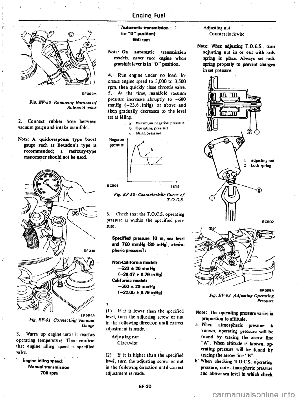
a
Maximum
negative
pressure
b
Operating
pressure
c
Idling
pressure
Nega
ive
pressure
EC502
Time
Fig
EF
52
Characteristic
Curve
of
T
O
C
S
6
Check
that
the
T
O
C
s
operating
pressure
is
within
the
specified
pres
sure
Specified
pressure
0
m
sea
level
end
760
mmHg
30
inHgl
atmOs
pheric
pressure
Non
Califomia
models
520
20
mmHg
20
47
0
79
inHg
California
models
560
20
mmHg
22
05
9
79
inHgl
7
I
If
it
is
lower
than
the
specified
level
turn
the
adjusting
screw
or
nut
in
the
following
direction
until
correct
adjustment
is
made
Adjusting
nut
Clockwise
2
If
it
is
higher
than
the
specified
levei
turn
the
adjusting
screw
or
nut
in
the
following
direction
until
correct
adjustment
is
made
EF
20
Adjusting
nut
Counterclockwise
Note
When
adjusting
T
O
C
S
turn
adjusting
nut
in
or
out
with
lock
spring
in
place
Always
set
lock
spring
properly
to
prevent
changes
in
set
pressure
Vo
1
Adjusting
nut
2
Lock
spring
n
EC802
EF055A
Fig
EF
53
Adjusting
Ope
llting
Pre
3ure
Note
The
operating
pressure
varies
in
proportion
to
altitude
a
When
atmospheric
pressure
is
known
operating
pressure
will
be
found
by
tracing
the
arrow
line
A
When
altitude
is
known
op
erating
pressure
will
be
found
by
tracing
the
arrow
line
B
b
When
checking
T
O
C
S
operating
pressure
note
atmospheric
pressure
and
above
sea
level
in
which
check
Page 151 of 548
EC173A
Fig
EC
95
Disconnecting
Vacuum
Switching
Valve
Connector
3
Apply
parking
brake
and
keep
brake
pedal
fully
depressed
4
Check
continuity
between
two
specified
terminals
ai
function
test
connector
with
gearshift
lever
in
R
or
N
position
The
top
detecting
switch
is
func
tioning
properly
if
the
continuity
is
as
following
table
If
not
replace
the
switch
N
position
No
R
position
Yes
Note
At
idling
CAUTION
Never
race
the
engine
or
car
will
creep
r
q
EC329A
Fig
EC
96
Checking
Top
Detecting
Switch
Arr
model
Emission
Control
System
Entire
system
Non
California
AfT
models
except
Canada
1
Ensure
that
vacuum
hoses
are
properly
connected
to
their
positions
And
confirm
that
gearshift
lever
is
in
P
position
2
Disconnect
vacuum
hose
atdis
tributor
vacuum
controller
3
While
engine
cooling
wat
r
is
be
low
SOoC
1220F
race
engine
and
check
vacuum
for
distributor
If
vacu
um
is
felt
check
thermal
vacuum
valve
3
port
type
4
After
engine
is
sufficiently
warmed
up
repeat
the
above
opera
tion
In
this
case
vacuum
should
be
felt
If
not
check
thermal
vacuum
valve
Vacuu
m
switching
valve
If
spark
timing
does
not
vary
at
all
in
checking
entire
system
check
vacu
um
switching
valve
i
follows
I
Warm
up
engine
sufficiently
2
Disconnect
vacuum
switching
valve
lead
wires
3
Set
timing
light
and
keep
engine
speed
at
approximately
1
600
rpm
On
AfT
models
geaishiftlever
should
be
in
N
or
P
4
Apply
l2V
battery
voltage
to
one
of
two
lead
wires
from
vacuum
switching
valve
Then
connect
the
other
lead
wire
to
ground
At
this
time
spark
timing
should
change
appioximately
by
50
If
it
does
not
replace
vacuum
switching
valve
EC175A
Fig
EC
97
Checking
Vacuum
Switching
Valv
Thermal
vacuum
valve
3
port
type
U
s
A
models
except
FU
model
Remove
thermal
vacuum
valve
from
engine
Inhale
air
from
port
of
spark
EC32
timing
amttol
systetn
andcheck
to
sure
that
thermal
vacuum
valve
opens
or
closes
in
response
to
its
tempera
ture
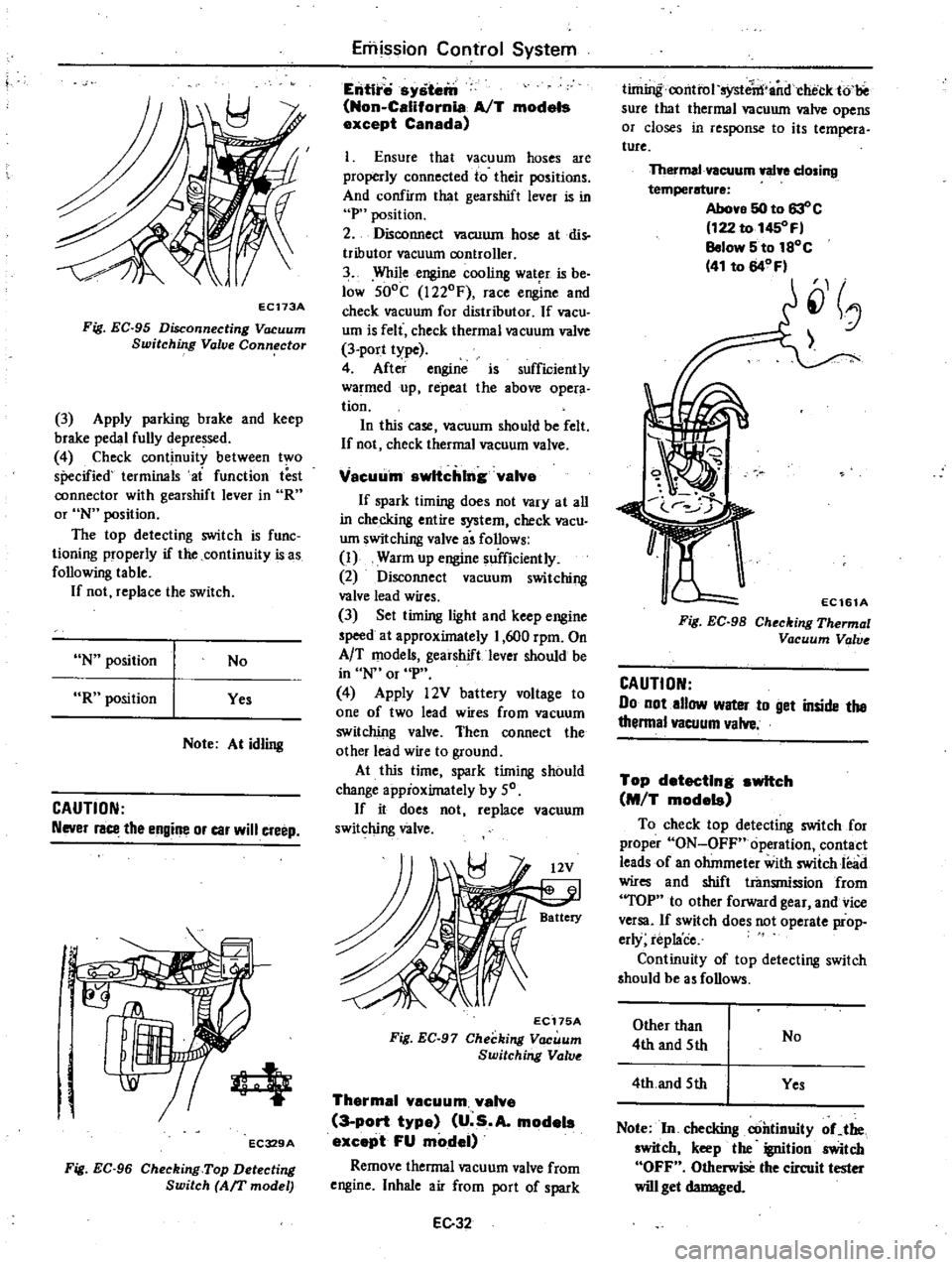
Thermal
vacuum
walye
closing
temperature
Above
50
to
63
c
122
to
1450
F
Below
5
to
1SoC
41
to
64
Fl
J
EC161A
Fig
EC
98
Checking
Thermal
Vacuum
Valv
CAUTION
Do
not
allow
water
to
get
inside
the
thenna
vacuum
valve
Top
detecting
switch
M
T
models
To
check
top
detecting
switch
for
proper
ON
OFF
operation
contact
leads
of
an
ohmmeter
with
swiich
lead
wires
and
shift
transmiosion
from
TOP
to
other
forward
gear
and
vice
versa
If
switch
does
not
operate
prop
erly
replace
Continuity
of
top
detecting
switch
should
be
a
follows
Other
than
4th
and
5th
No
4th
and
5th
Yes
Note
In
checking
continuity
oCthe
switch
keep
the
ignition
switch
OFF
Otherwise
the
circuit
tester
will
get
damaged
Page 160 of 548
WARNING
Never
touch
positive
and
negative
terminals
at
the
same
time
with
are
hands
Th
l
Il
d
result
in
injury
CHECKING
ELECTROLYTE
LEVEL
Remove
six
vent
plugs
and
check
for
electrolyte
level
in
each
cell
If
necessary
pour
distilled
water
CHECKING
SPECIFIC
GRAVITY
Specific
gravity
of
battery
electro
lyte
is
tested
by
a
hydrometer
If
the
state
of
charge
of
battery
is
below
70
battery
must
be
recharged
or
battery
electrolyte
concentration
ad
justed
EE473
Fig
EE
l
Charging
Condition
Engine
Electrical
System
BATTERY
The
gravity
of
electrolyte
changes
0
0007
for
every
loe
I
80F
temper
ature
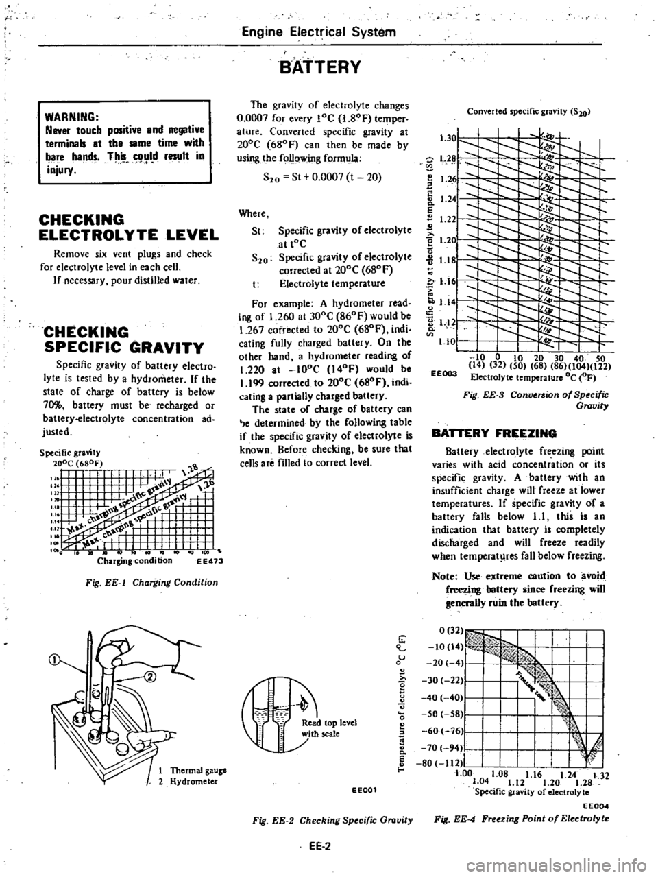
Converted
specific
gravity
at
200e
680F
can
then
be
made
by
using
the
following
form
la
S20
St
0
0007
t
20
Where
St
Specific
gravity
of
electrolyte
at
tOe
S20
Specific
gravity
of
electrolyte
corrected
al
200e
680
F
t
Electrolyte
temperature
For
example
A
hydrometer
read
ing
of
1
260
at
300e
860F
would
be
1
267
corrected
to
200e
680F
indi
cating
fully
charged
battery
On
the
olher
hand
a
hydrometer
reading
of
1
220
at
lOoe
I40F
would
be
I
199
corrected
to
200e
680F
indi
cating
a
partially
charged
battery
The
state
of
charge
of
battery
can
e
determined
by
the
following
table
if
the
specific
gravity
of
electrolyte
is
known
Before
checking
be
sure
that
cells
are
filled
to
correct
level
Converted
specific
gravity
S20
l
301
l
Z
L2
I
1
2
I
Ii
8
1
24
E
1
22
2
t
2e
u
1
18
c
i
1
161
1
141
2
1
12
Q
1
10
I
to
0
to
20
30
40
50
14
32
50
68
86
104
122
EEOO3
Electrolyte
temperature
Oc
OF
Fig
EE
3
Conversion
of
Specific
Gravity
BATTERY
FREEZING
Battery
electrolyte
freezing
point
varies
with
acid
concentration
or
its
specific
gravity
A
battery
with
an
insufficient
charge
will
freeze
al
lower
temperatures
If
specific
gravity
of
a
battery
falls
below
1
I
this
is
an
indication
that
battery
is
completely
discharged
and
will
freeze
readily
when
temperat
res
fall
below
freezing
Note
Use
extreme
caution
to
avoid
freezing
battery
since
freezing
will
generally
ruin
the
battery
1
u
B
I
r
eleYel
60
76
Ji
I
k
E
I
I
d
8
70
94
80
112
I
I
f
1
Thermal
gauze
1
00
1
08
1
16
1
24
1
32
2
Hydrometer
1
04
1
12
1
20
1
28
EE001
Specific
gravity
of
electrolyte
EE004
Fig
EE
2
Checking
Specific
Gravity
Fig
EE
4
Freezing
Point
of
Electrolyte
EE
2
Page 214 of 548

Condition
Clutch
slips
Clutch
drags
Clutch
TROUBLE
DIAGNOSES
AND
CORRECTIONS
Probable
cause
and
testing
Corrective
action
Slipping
of
clutch
may
be
noticeable
when
any
of
the
following
symptoms
is
encountered
during
operation
I
Car
will
not
respond
to
erigine
speed
during
acceleration
2
Insufficient
car
speed
3
Lack
of
power
during
uphill
driving
Some
of
the
above
conditions
may
also
be
attributable
to
engine
problem
First
determine
whether
engine
or
clutch
is
causing
the
problem
If
slipping
clutch
is
left
unheeded
wear
and
or
overheating
will
occur
on
clutch
facing
to
such
an
extent
that
it
is
no
longer
serviceable
TO
TEST
FOR
SLIPPING
CLurCH
proceed
as
follows
During
upgrade
havelling
run
engine
at
about
40
to
50
km
h
25
to
31
MPH
with
gear
shift
lever
in
3rd
speed
position
shift
into
highest
gear
and
t
the
same
time
rev
up
engine
If
clutch
is
slipping
car
willnot
readily
respond
to
depression
of
accelerator
pedal
Clutch
facing
warn
excessively
Oil
or
grease
on
clutch
facing
Warped
clutch
cover
or
pressure
plate
Replace
Replace
Repair
or
replace
Dragging
clu
tch
is
particularly
noticeable
when
shifting
gears
especially
into
low
gear
TO
TEST
FOR
DRAGGING
CLurCH
proceed
as
follows
I
Start
engine
Disengage
clutch
Shift
into
reverse
gear
and
then
into
Neutral
Gradually
increase
engine
speed
and
again
shift
into
reverse
gear
If
clutch
is
dragging
gear
grating
is
heard
when
shifting
gears
from
Neutral
into
Reverse
2
Stop
engine
and
shift
gears
Conduct
this
test
at
each
gear
position
3
In
step
2
gears
are
shifted
smoothly
except
1st
speed
position
at
idling
a
If
dragging
is
encountered
at
the
end
of
shifting
check
condition
of
synchro
mechanism
in
transmission
b
If
dragging
is
encountered
at
the
beginning
of
shifting
proceed
to
step
4
below
4
Push
change
lever
toward
Reverse
ide
depress
pedal
to
check
for
free
travel
of
pedal
a
If
pedal
can
be
depressed
further
check
clutch
for
condition
b
If
pedal
cannot
be
depressed
further
proceed
to
step
5
below
5
Check
clutch
control
pedal
height
pedal
free
play
free
travel
withdrawal
lever
play
etc
If
any
abnormal
condition
does
not
exist
and
if
pedal
cannot
be
depressed
further
check
clutch
for
condition
Clutch
disc
runout
or
warped
Wear
or
rust
on
hub
splines
in
clutch
disc
Diaphragm
spring
toe
height
out
of
adjustment
or
toe
tip
worn
Worn
or
improperly
installed
parts
Replace
Clean
and
lubricate
with
grease
or
replace
Adjust
or
replace
Repair
or
replace
CL12
Page 518 of 548
COMPRESSOR
OIL
LEVEL
CHECK
The
oil
used
to
lubricate
compres
sor
circulates
into
system
from
the
oil
sump
while
compressor
is
operating
Therefore
to
correctly
measure
com
pressor
oil
the
amount
of
oil
flowing
to
system
must
be
considered
If
a
considerable
amount
of
leakage
of
refrigerant
gas
happens
the
leakage
of
compressor
oil
is
also
considered
There
will
be
no
compressor
oil
leak
age
from
a
completely
sealed
system
When
system
operates
under
satisfying
condition
the
compressor
oil
level
check
is
unnecessary
When
checking
the
level
of
com
pressor
oil
or
when
replacing
any
component
part
of
the
system
use
the
following
service
procedure
This
facio
litates
to
return
oil
to
compressor
1
Operate
compressor
at
engine
idling
speed
I
OOO
rpm
or
below
with
controls
set
for
maximum
cooling
and
high
blower
speed
for
10
to
15
minutes
in
order
to
return
com
pressor
oil
to
compressor
2
Stop
the
engine
and
discharge
refrigerant
of
system
and
then
remove
compressor
from
the
car
3
Remove
compressor
filler
plug
Drain
compressor
oil
from
compres
sor
oil
sump
and
measure
the
amount
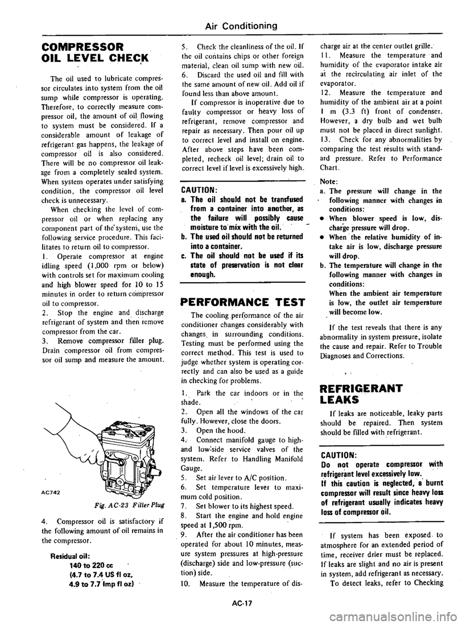
AC742
Fig
AC
23
Filler
Plug
4
Compressor
oil
is
satisfactory
if
the
following
amount
of
oil
remains
in
the
compressor
Residual
oil
140
to
220
cc
4
7
to
7
4
US
fl
oz
4
9
to
7
7
Imp
fl
oz
Air
Conditioning
5
Check
the
cleanliness
of
the
oil
If
the
oil
contains
chips
or
other
foreign
material
clean
oil
sump
with
new
oil
6
Discard
the
used
oil
and
fill
with
the
same
amount
of
new
oil
Add
oil
if
found
less
than
above
amount
If
compressor
is
inoperative
due
to
faulty
compressor
or
heavy
loss
of
refrigerant
remove
compressor
and
repair
as
necessary
Then
pour
oil
up
to
correct
level
and
install
on
engine
After
above
steps
have
been
com
pleted
recheck
oil
level
drain
oil
to
correct
level
if
level
is
excessively
high
CAUTION
a
The
oil
should
not
be
transfused
from
a
container
into
another
as
the
failure
will
possibly
cause
moisture
to
mix
with
the
oil
b
The
used
oil
should
not
be
returned
into
a
container
c
The
oil
should
not
be
used
if
its
state
of
preservation
is
not
clear
enough
PERFORMANCE
TEST
The
cooling
per
ormance
of
the
air
conditioner
changes
considerably
with
changes
in
surrounding
conditions
Testing
must
be
performed
using
the
correct
method
This
test
is
used
to
judge
whether
system
is
operating
cor
rectly
and
can
also
be
used
as
a
guiqe
in
checking
for
problems
1
Park
the
car
indoors
or
in
the
shade
2
Open
all
the
windows
of
the
car
fully
However
close
the
doors
3
Open
the
hood
4
Connect
manifold
gauge
to
high
and
low
side
service
valves
of
the
system
Refer
to
Handling
Manifold
Gauge
5
Set
air
lever
to
AIC
position
6
Set
temperature
lever
to
maxi
mum
cold
position
7
Set
blower
to
its
highest
speed
8
Start
the
engine
and
hold
engine
speed
at
1
500
rpm
9
After
the
air
conditioner
has
been
operated
for
about
10
minutes
meas
ure
system
pressures
at
high
pressure
discharge
side
and
low
pressure
suc
tion
side
10
Measure
the
temperature
of
dis
AC
17
charge
air
at
the
center
outlet
grille
11
Measure
the
temperature
and
humidity
of
the
evaporator
in
take
air
at
the
recirculating
air
inlet
of
the
evaporator
12
Measure
the
temperature
and
humidity
of
the
ambient
air
at
a
point
I
m
3
3
ft
front
of
condenser
However
a
dry
bulb
and
wet
bulb
must
not
be
placed
in
direct
sunlight
13
Check
for
any
abnormalities
by
comparing
the
test
results
with
stand
ard
pressure
Refer
to
Performance
Chart
Note
a
The
pressure
will
change
in
the
following
manner
with
changes
in
conditions
When
blower
speed
is
low
dis
charge
pressure
will
drop
When
the
relative
humidity
of
in
take
air
is
low
discharge
pressure
will
drop
b
The
temperature
will
change
in
the
following
manner
with
changes
in
conditions
When
the
ambient
air
temperature
is
low
the
outlet
air
temperature
will
become
low
If
the
test
reveals
that
there
is
any
abnormality
in
system
pressure
isolate
the
cause
and
repair
Refer
to
Trouble
Diagnoses
and
Corrections
REFRIGERANT
LEAKS
If
leaks
are
noticeable
leaky
parts
should
be
repaired
Then
system
should
be
fIlled
with
refrigerant
CAUTION
00
not
operate
compressor
with
refrigerant
level
excessively
low
If
this
caution
is
neglected
a
burnt
compressor
will
result
since
heavy
loss
of
refrigerant
usually
indicates
heavy
loss
of
compressor
liil
I
f
system
has
been
exposed
to
atmosphere
for
an
extended
period
of
time
I
receiver
drier
must
be
replaced
If
leaks
are
slight
and
no
air
is
present
in
system
add
refrigerant
as
necessary
To
detect
leaks
refer
to
Checking