warning light DATSUN 210 1979 Service Manual
[x] Cancel search | Manufacturer: DATSUN, Model Year: 1979, Model line: 210, Model: DATSUN 210 1979Pages: 548, PDF Size: 28.66 MB
Page 19 of 548
sion
pressure
chances
are
that
piston
rings
are
worn
or
damaged
2
If
pressure
stays
low
the
likeli
hood
is
that
valve
is
sticking
or
seating
Engine
Tune
up
improperly
3
If
cylinder
compression
in
any
two
adjacent
cylinders
is
low
and
if
adding
oil
does
not
help
the
compres
sion
there
is
leakage
past
the
gasketed
surface
Oil
and
water
in
combustion
cham
bers
can
result
from
this
problem
IGNITION
AND
FUEL
SYSTEM
CHECKING
BATTERY
I
Remove
six
vent
plugs
and
check
electrolyte
level
in
each
battery
cell
If
necessary
pour
distilled
water
Overflow
Correct
Shortage
t
t
j
t
t
t
EE358
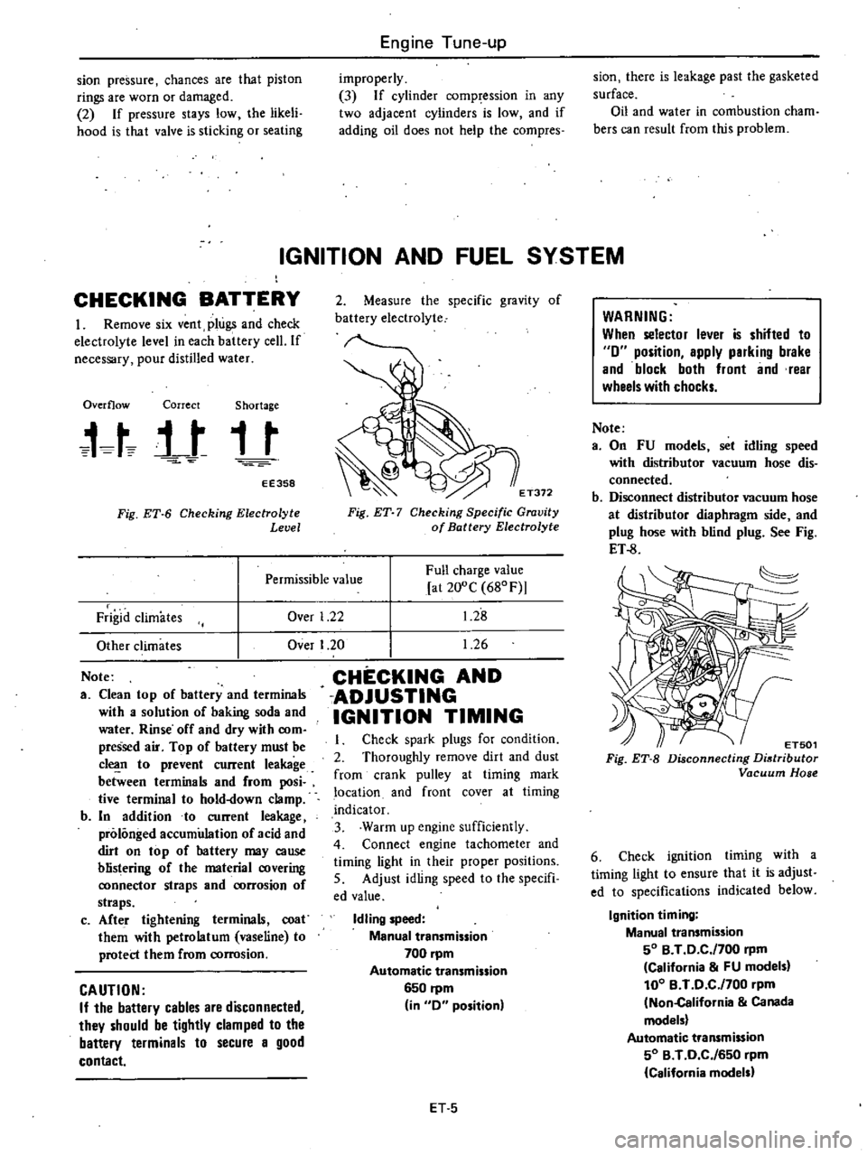
Fig
ET
6
Checking
Electrolyte
Level
2
Measure
the
specific
gravity
of
battery
electrolyte
E
T372
Fig
ET
7
Checking
Specific
Gravity
of
Battery
Electrolyte
Over
1
22
Full
charge
value
at
200C
680F
1
28
1
26
Permissible
value
Frigid
climates
Other
climates
Note
a
Clean
top
of
battery
and
terminals
with
a
solution
of
baking
soda
and
water
Rinse
off
and
dry
with
com
pressed
air
Top
of
battery
must
be
c1
n
to
prevent
current
leakage
between
terminals
and
from
posi
tive
terminal
to
hold
down
clamp
b
In
addition
to
current
leakage
prolonged
accumulation
of
acid
and
dirt
on
top
of
hattery
may
cause
blistering
of
the
material
covering
ronnector
straps
and
rorrosion
of
straps
c
Afte
r
tightening
terminals
coat
them
with
petrolatum
vaseline
to
protect
them
from
corrosion
CAUTION
If
the
battery
cables
are
disconnected
they
should
be
tightly
clamped
to
the
battery
terminals
to
secure
a
good
contact
Over
I
20
CHECKING
AND
ADJUSTING
IGNITION
TIMING
Check
spark
plugs
for
condition
2
Thoroughly
remove
dirt
and
dust
from
crank
pulley
at
timing
mark
location
and
front
cover
at
timing
indicator
3
Warm
up
engine
sufficiently
4
Connect
engine
tachometer
and
timing
light
in
their
proper
positions
5
Adjust
idling
speed
to
the
specifi
ed
value
Idling
speed
Manual
transmission
700
pm
Automatic
transmission
6S0
rpm
in
0
position
ET
S
WARNING
When
selector
lever
is
shifted
to
0
position
apply
parking
brake
and
block
both
front
and
rear
wheels
with
chocks
Note
a
On
FU
models
set
idling
speed
with
distributor
vacuum
hose
dis
connected
b
Disconnect
distributor
vacuum
hose
at
distributor
diaphragm
side
and
plug
hose
with
blind
plug
See
Fig
ET
8
ET501
Fig
ET
B
Disconnecting
Distributor
Vacuum
Hose
6
Check
ignition
timing
with
a
timing
light
to
ensure
that
it
is
adjust
ed
to
specifications
indicated
below
Ignition
timing
Manual
transmission
SO
B
T
0
C
f700
rpm
California
FU
models
100
B
T
0
C
f700
pm
Non
California
Canada
models
Automatic
transmission
SO
B
T
0
C
f6S0
rpm
California
models
Page 76 of 548
Not
Pump
rotors
and
body
are
not
serv
iced
separatdy
If
pump
rotors
or
body
are
damaged
or
worn
replace
ment
of
the
entire
oil
pump
assembly
isnecessary
OIL
PRESSURE
REGULATOR
VALVE
The
oil
pressure
regulator
valve
is
not
adjustable
At
the
released
posi
tion
the
valve
permits
the
oil
to
by
pass
through
the
passage
in
the
pump
cover
to
the
inlet
side
of
the
pump
Check
regulator
valve
spring
to
ensure
that
spring
tension
is
correct
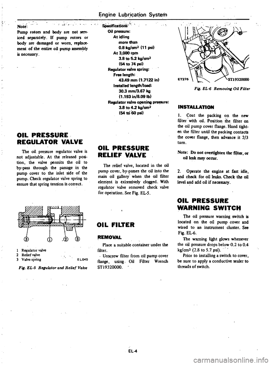
no
1
Regulator
valve
2
Relief
valve
3
Valve
spring
E
L045
Fig
EL
5
Regulator
and
Reli
Vatv
Engine
Lubrication
System
8Peciflcatlons
Oil
pressure
At
idling
more
than
O
Blrg
an2
11
psi
At
3
000
rpm
3
B
to
5
2lrg
an2
54
to
74
psi
Regulator
ai
spring
Free
length
43
49
rom
1
7122
in
InstoJlod
l
ngth
load
30
3
mm
3
67
kg
1
193
inJB
09lbl
Regulator
val
o
ning
pressur
3
8
to
4
2
lrg
an2
54
1060
psi
OIL
PRESSURE
RELIEF
VALVE
The
relief
valve
located
in
the
oil
pump
cover
by
passes
the
oil
into
the
main
oil
gallery
when
the
oil
filter
elem
nt
is
exCessively
clogged
With
regula
tor
valve
removed
check
valve
for
operation
See
Fig
EL
5
OIL
FILTER
tEMOVAL
Place
a
suitable
container
under
the
f1lter
Unscrew
f1lter
from
oil
pump
cover
flange
using
Oil
Filter
Wrench
STl9320000
EL
4
Fig
EL
6
Removing
Oil
Filter
INSTALLAnON
I
Coat
the
packing
on
the
new
f1lter
with
oil
Position
the
f1lter
on
the
oil
pump
cover
flange
Hand
tight
en
the
f11ter
until
the
packing
contacts
the
cover
flange
then
advance
it
2
3
tum
Note
Do
not
overtighten
the
fiIter
or
oil
leak
may
occur
2
Operate
the
engine
at
fast
idle
and
check
for
oil
leaks
Check
the
oil
level
and
add
oil
if
necessary
OIL
PRESSURE
WARNING
SWITCIt
The
oil
pressure
warning
switch
is
located
on
the
oil
pump
cover
and
wired
to
an
instrument
cluster
See
Fig
EL
6
The
warning
light
glows
whenever
the
oil
pressure
drops
below
0
2
to
0
4
kg
cm1
2
8
to
5
7
psi
Prior
to
installing
a
switch
to
cover
I
be
sure
to
apply
a
conductive
sealer
to
threads
of
switch
Page 150 of 548
INSPECTION
Entire
system
U
S
A
MIT
models
except
FU
mo
el
1
Ensure
that
wiring
connectors
are
tight
in
pla
ce
2
Ensure
that
vacuum
hoses
are
properly
cof
1o
c
ed
to
their
positions
3
Ensure
that
distributor
vacuum
controller
properly
functions
4
Set
timing
light
and
start
engine
S
While
engine
cooling
water
tem
pefature
is
below
SOOC
I220F
check
function
of
system
as
follows
WARNING
To
protect
against
accidental
for
ward
surge
engage
parking
brake
firmly
while
above
check
is
being
made
I
Run
engine
and
keep
it
at
ap
proximately
1
600
rpm
2
Disengage
clutch
Shift
gears
in
top
3rd
then
neutral
positions
Read
spark
timing
in
respective
shift
posi
tions
The
system
is
properly
functioning
if
spark
timir
g
does
not
change
If
t
changes
check
thefmal
vacuum
valve
3
port
type
Note
Ensure
that
thermal
vacuum
wIve
is
closed
when
cooling
water
i
below
5
to
lSoC
41
to
640F
or
above
SO
to
630C
122
to
14S0F
I
6
After
the
engine
has
been
warmed
up
sufficiently
check
the
function
of
the
system
again
in
the
I
Same
manner
The
system
is
properly
functioning
if
spark
iimin
advances
in
top
posi
tion
If
not
check
thefmal
vacuum
valve
control
circuit
or
vaeu
um
switching
valve
Entire
system
FU
model
and
Canada
MIl
models
I
Ensure
that
wiri
lg
connectors
are
tight
in
place
Emission
Control
System
2
Ensure
that
vacuum
hoses
are
properly
connected
to
their
positions
3
Ensure
that
distributor
vacuum
controller
properly
fu
ctions
4
Set
timing
light
WARNING
To
protect
against
accidental
for
ward
surge
engage
parking
brake
firmly
while
above
check
is
being
made
5
Run
engine
and
keep
it
at
ap
proximately
1
600
1
m
6
Disengage
clutch
Shift
gears
in
4th
5th
ihen
neutral
positions
Read
spark
timing
in
respective
shift
posi
tions
The
system
is
properly
functioning
if
spark
timing
advances
in
top
gear
position
If
spark
timing
does
not
vary
at
all
in
tests
des
rilied
in
step
6
above
check
control
circuit
or
vacuum
switching
valve
Entire
system
California
AIT
models
I
Ensure
th
t
wiring
connectors
are
tight
in
place
2
Ensure
that
vacuum
hoses
are
properly
coIDwcted
to
thejr
positions
3
Ensure
that
distributor
vacuum
controller
function
s
properly
4
Set
timing
light
and
staft
engine
S
While
engine
cooling
water
tem
perature
is
below
SOOC
1220F
check
the
function
of
the
system
as
follows
WARNING
To
protect
againSt
accidental
for
ward
surge
engage
parking
brake
firmly
while
above
check
is
being
made
I
Run
engine
and
keep
it
at
ap
proximately
1
600
rpm
at
P
range
2
Make
a
short
circuit
between
the
specified
two
terminals
at
function
te
t
connector
EC31
The
entire
system
except
for
the
top
switch
is
properly
functioning
if
spark
timing
does
not
change
If
it
changes
check
the
thermal
vacuum
valve
3
pori
type
CAUTION
Pay
attention
not
to
make
a
short
circuit
between
other
terminals
than
the
specified
terminals
or
electrical
system
of
car
will
get
damaged
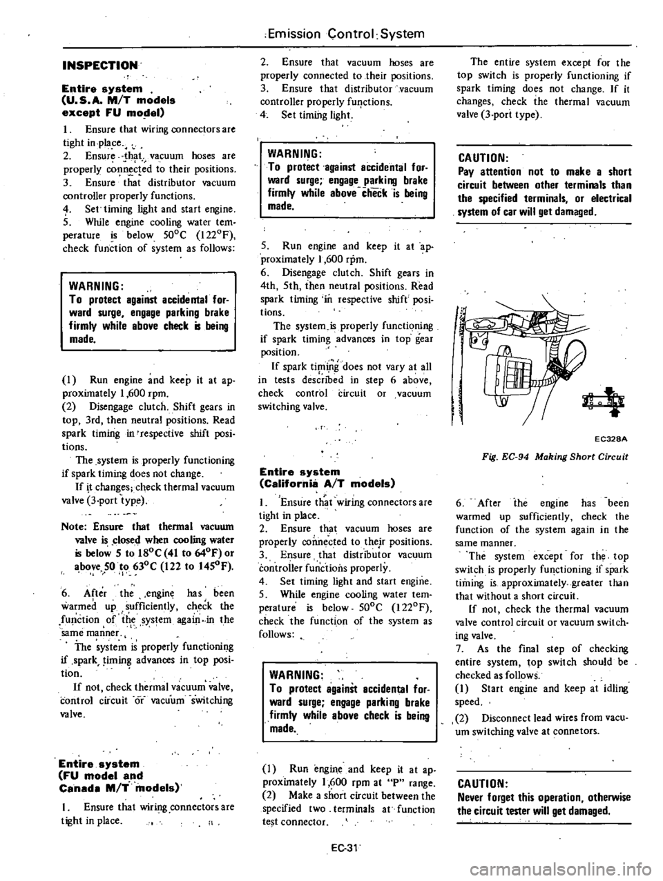
4
EC328A
Fig
EC
94
Making
Short
Circuit
6
After
ihe
engine
has
been
warmed
up
sufficiently
check
the
function
of
the
system
again
in
the
same
manner
The
system
except
for
the
top
switch
is
properly
fU
lctioning
if
spark
timing
is
approximately
greater
than
that
without
a
short
circuit
If
not
check
the
thermal
vacuum
valve
control
circuit
or
vacuum
switch
ing
valve
7
As
the
final
step
of
checking
entire
system
top
switch
should
be
checked
as
follows
1
Start
engine
and
keep
at
idling
speed
2
Disconnect
lead
wires
from
vacu
um
switching
valve
at
connetors
CAUTION
Never
forget
this
operation
otherwise
the
circuit
tester
will
get
damaged
Page 175 of 548
Engine
Electrical
System
6
Tighten
through
bolts
rfl
Tightening
torque
Through
bolts
60
to
70
kg
cm
52
to
61
in
lb
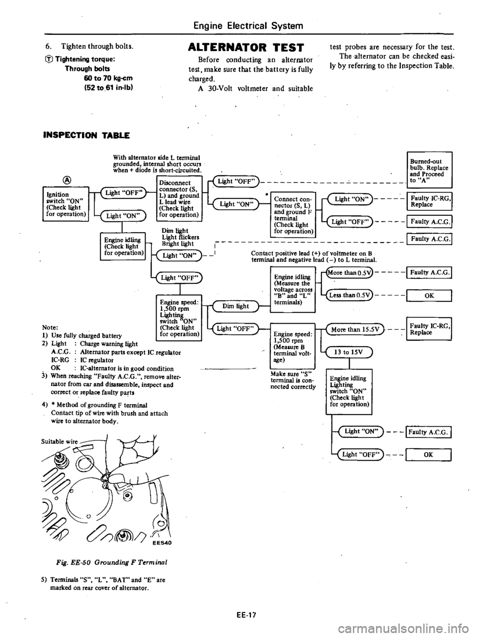
ALTERNATOR
TEST
Before
conducting
an
alternator
test
make
sure
that
the
battery
is
fully
charged
A
30
Volt
voltmeter
and
suitable
INSPECTION
TABLE
With
alternator
aide
L
tenninal
grounded
internal
short
occurs
when
diode
is
short
circuited
@
test
probes
are
necessary
for
the
test
The
alternator
can
be
checked
easi
ly
by
referring
to
the
Inspection
Table
Bumed
out
bulb
Replace
and
Proceed
toUA
Ignition
switch
ON
Check
light
for
operation
Disconnect
Light
OFF
f
Light
OFF
connector
S
L
and
ground
L
lead
wire
Light
ON
Check
light
for
operation
Light
ON
I
Faulty
IC
RG
Replace
Connect
con
nector
S
L
and
ground
F
a1light
Light
OFF
I
FaultyA
C
G
I
Dim
light
for
operation
tf
i
rs
1
I
Faulty
A
C
G
I
Light
ON
I
Contact
positive
lead
of
voltmeter
on
B
lennina
and
negative
lead
to
L
tenninal
Light
ON
1
Engine
idling
Check
light
for
operation
Light
OFF
I
Engine
idling
Measure
the
voltage
across
B
and
L
terminals
Engine
speed
1
500
rpm
Ligh
tin
switch
ON
Check
light
for
operation
r
Dim
light
Light
OFF
Note
1
Use
fully
charged
battery
2
Light
Charge
warning
light
A
C
G
Alternator
parts
except
IC
regu
tor
IC
RG
IC
n
guJator
OK
IC
altemator
is
in
good
condition
3
When
reaching
Faulty
A
C
G
remove
alter
nator
from
car
and
disassemble
inspect
and
correct
or
replace
faulty
parts
Engine
speed
1
500
rpm
Measure
B
terminal
volt
sge
Make
sure
S
terminal
is
con
nected
correctly
4
Method
of
grounding
F
terminal
Contact
tip
of
wire
with
brush
and
attach
wire
to
alternator
body
Suitable
wire
I
Fig
EE
50
Grounding
F
Terminal
5
Terminals
S
L
BA
Tn
and
E
are
marked
on
rear
cover
of
alternator
EEl7
More
thanO
5V
I
Faulty
A
e
G
1
Less
thanO
5V
I
OK
T
Mon
than
15
5V
I
Z
C
RG
I
I3
to
15V
Engine
idling
Lighting
switch
ON
Check
light
for
operation
Light
ON
I
Faulty
A
C
G
I
Light
OFF
I
OK
Page 354 of 548
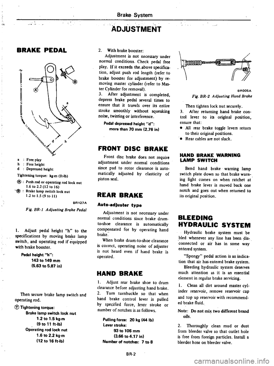
BRAKE
PEDAL
a
a
Fr
play
h
Free
height
d
Depressed
height
Tightening
torque
Icg
m
ft
tb
@
@
Push
rod
or
operating
rod
lock
nut
1
6
to
2
2
12
to
16
Brake
lainp
switch
lock
nut
1
2
to
I
5
9
to
11
BR121A
Fig
BR
1
Adjusting
Broke
Pedal
I
Adjust
pedal
height
h
to
the
specifications
by
moving
brake
lamp
switch
and
operating
rod
if
equipped
with
brake
booster
Pedal
height
h
143
to
149
mm
5
63
to
5
87
inl
Then
secure
brake
lamp
switch
and
operating
rod
C
l
Tightening
tOlque
Blake
lamp
witch
lock
nut
1
2
to
1
5
kg
m
9
to
11
ft
lb
Operating
lad
lock
nut
1
6
to
2
2
kg
m
12
to
16
ft
b
Brake
System
ADJUSTMENT
2
With
brake
booster
Adjustment
is
not
necessary
under
normal
conditions
Check
pedal
free
play
If
it
exceeds
the
above
specifica
tion
adjust
push
rod
length
refer
to
brake
booster
for
adjustment
by
re
moving
master
cylinder
rerer
to
Mas
ter
Cylinder
for
removal
3
After
adjustment
is
completed
depress
brake
pedal
several
times
to
ensure
that
it
travels
over
its
entire
stroke
smoothly
without
squeaking
noise
twisting
or
interference
Pedal
depr
d
Might
d
more
than
70
mm
2
76
in
FRONT
DISC
BRAKE
Front
disc
brake
does
not
require
adjustment
under
normal
conditions
since
pad
to
rotor
clearance
is
auto
malically
adjusted
by
elasticity
of
piston
seal
REAR
BRAKE
Auto
edJuster
type
Adjustment
is
not
necessary
under
normal
conditions
since
brake
drum
t
shoe
clearance
is
automatically
compensated
for
by
operating
hand
brake
Wlien
brake
drum
to
shoe
clearance
is
correct
operating
noise
of
adjuster
is
not
heard
even
if
hand
brake
is
operated
HAND
BRAKE
I
Adjust
rear
brake
shoe
to
drum
clearance
before
adjusting
hand
brake
2
Turn
turnbuckle
so
that
when
hand
brake
control
lever
is
pulled
by
specified
force
lever
stroke
or
number
of
notches
is
as
follows
Pulling
fOil
20
kg
44
Ib
lever
stroke
93
to
106
mm
3
66
to
4
17
in
Numbel
of
notches
7
to
8
BR
2
f
BAQ05A
Fig
BR
2
Adjusting
Hand
Brake
Then
tighten
lock
nut
securely
3
After
returning
hand
brake
con
trol
lever
to
its
original
position
ensure
that
e
All
rear
brake
toggle
levers
return
to
their
original
positions
Rear
cables
are
not
slack
HAND
BRAKE
WARNING
LAMP
SWITCH
Bend
hand
brake
warning
lamp
switch
plate
down
so
that
brake
warn
ing
light
comes
on
when
ratchet
at
hand
brake
lever
is
moved
back
one
notch
and
goes
out
when
returned
to
its
original
position
BLEEDING
HYDRAULIC
SYSTEM
Hydraulic
brake
system
must
be
bled
whenever
any
line
has
been
dis
connected
or
air
has
in
some
way
entered
system
Spongy
pedal
action
is
an
indica
tion
that
air
has
entered
brake
system
Bleeding
hydraulic
system
deserves
much
attention
as
it
is
an
essential
element
in
regular
brake
servicing
Clean
all
dirt
around
master
cyl
inder
reservoir
remove
reservoir
cap
and
top
up
reservoir
with
recommend
edbrake
fluid
Note
Do
not
mix
two
different
brand
oils
2
Thoroughly
clean
mud
or
dust
from
bleeder
valve
so
that
outlet
hole
is
free
from
foreign
particles
Install
a
bleeder
hose
on
bleeder
valve
Page 362 of 548
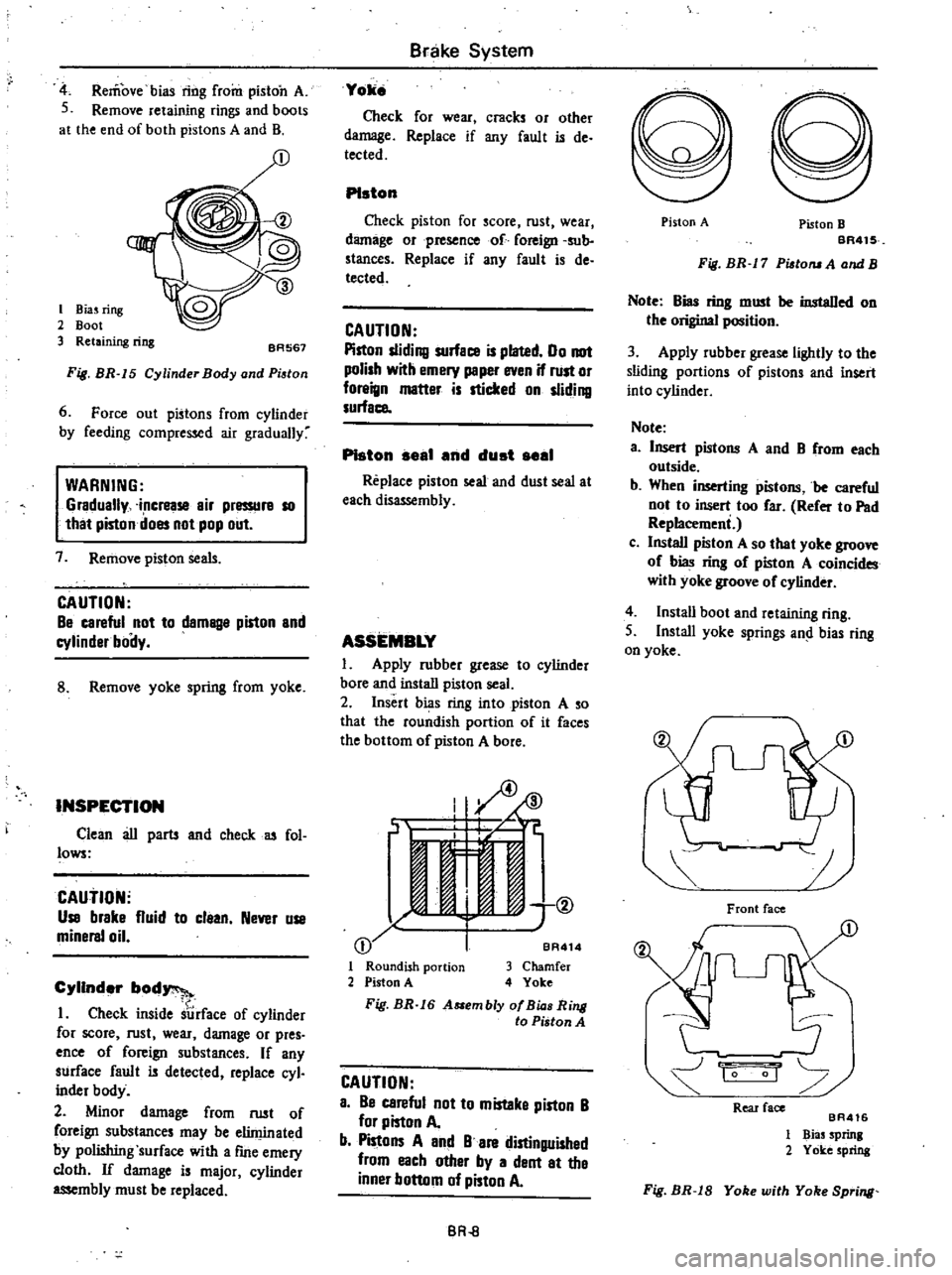
Remove
bias
ring
from
piston
A
S
Remove
retaining
rings
and
boots
at
the
end
of
both
pistons
A
and
B
I
Biuring
2
Boot
3
Retaining
ring
BA567
Fig
BR
15
Cylinder
Body
and
Pi
tan
6
Force
out
pistons
from
cylinder
by
feeding
compressed
air
gradually
WARNING
Gradually
increase
air
pressurs
10
that
piston
does
not
pop
out
7
Remove
piston
seals
CAUTION
Be
careful
not
to
damBlle
piston
and
cylinder
boily
8
Remove
yoke
spring
from
yoke
INSPECTION
Clean
au
parts
and
check
u
fol
lows
CAutiON
Use
brake
fluid
to
claan
Never
use
minersl
oil
Cylinder
bod
1
Check
inside
surface
of
cylinder
for
score
rust
wear
damage
or
pres
ence
of
foreign
substances
If
any
surface
fault
is
detected
replace
cyl
inder
body
2
Minor
damage
from
rust
of
foreign
substances
may
be
eliminated
by
polishing
surface
with
a
fme
emery
cloth
If
damage
is
major
cylinder
assembly
must
be
replaced
Brake
System
Yoke
Check
for
wear
cracks
or
other
damage
Replace
if
any
fault
is
de
tected
PIston
Check
piston
for
score
rust
wear
damage
orpresenco
of
foreign
sub
stances
Replace
if
any
fault
is
de
tected
CAUTION
Piston
sliding
surface
is
plated
00
not
polish
with
emery
peper
even
if
rust
or
foreign
matter
is
sticked
on
sliding
surface
PIston
seal
end
dust
seel
Replace
piston
seal
and
dust
seal
at
each
dis
mbly
ASSEMBLY
1
Apply
rubber
grease
to
cylinder
bore
and
install
piston
seal
2
Insert
bias
ring
into
piston
A
so
that
the
roundish
portion
of
it
faces
the
bottom
of
piston
A
bore
I
ID
J
if
C
jt
11
e
1
@
I
j
BA
I
Roundish
portion
3
Chamfer
2
Piston
A
4
Yoke
Fig
BR
16
A
embly
af
Bia
Ring
to
Piston
A
CAUTION
a
Be
careful
not
to
mistaka
piston
B
for
piston
A
b
Pistons
A
and
B
are
distinguished
from
each
other
by
a
dent
at
the
inner
bottom
of
piston
A
BR
8
Piston
A
Piston
B
BR41S
Fig
BR
17
Pisto
A
and
B
Note
Bias
ring
must
be
instaDed
on
the
original
position
3
Apply
rubber
grease
lightly
to
the
sliding
portions
of
pistons
and
insert
into
cylinder
Note
a
Insert
pistons
A
and
B
from
each
outside
b
When
inserting
pistons
be
careful
not
to
insert
too
far
Refer
to
Pad
Replacemeni
c
Install
piston
A
so
that
yoke
groove
of
bias
ring
of
piston
A
coincides
with
yoke
groove
of
cylinder
4
Instau
boot
and
retaining
ring
S
Install
yoke
springs
an
bias
ring
on
yoke
Front
face
1
1
0
Rear
face
BA416
1
Bias
Sprinl
2
Yoke
spring
Fig
BR
18
Yoke
with
Yoke
Spring
Page 369 of 548
Note
Front
cable
clevis
pin
and
cotter
pin
are
available
as
service
parts
Removal
of
eer
ceble
I
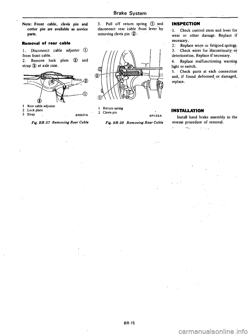
Disconnect
cable
adjuster
CD
from
front
cable
2
Remove
lock
plate
@
and
strap
00
at
axle
case
1
I
Rear
cable
adjuster
2
Lock
plate
3
Strap
BR037A
Fig
BR
37
Removing
Rear
Cable
Brake
System
3
Pull
off
return
spring
CD
and
disconnect
rear
cable
from
lever
by
removing
clevis
pin
@
@
I
Return
spring
2
Clevis
pin
6R122A
Fig
BR
38
Removing
Rear
Cable
BR
15
INSPECTION
I
Check
control
stem
and
lever
for
wear
or
other
damage
Replace
if
necessary
2
Replace
worn
or
fatigued
sprin
3
Check
wires
for
discontinuity
or
deterioration
Replace
ifheces
ary
4
Replace
malfunctioning
warning
light
or
switch
5
Check
parts
at
each
connection
and
if
found
defonned
or
damaged
replace
INSTALLATION
Install
hand
brake
assembly
in
the
reverse
procedure
of
removal
Page 441 of 548
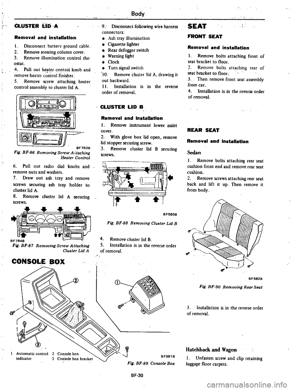
CLUSTER
I
IDA
Removal
and
installation
I
Disconnect
batterv
ground
cable
2
Remove
steering
column
cover
3
Remove
illumination
control
rhe
ostat
4
Pull
out
heater
control
knob
and
remove
heater
c
ntrol
finisher
5
Remove
screw
attaching
heater
control
assembly
to
cluster
lid
A
nQ
lQ
Ii
tl
rffmfLu
O
r
BF783B
Fig
BF
86
Removing
Screw
A
Uoching
Heater
Control
6
Pull
out
radio
dial
knobs
and
remove
nuts
and
washers
7
Draw
out
ash
tray
and
remove
screws
securing
ash
tray
holder
to
cluster
lid
A
B
Remove
cluster
lid
A
securing
screws
1
G808
iS
Ill
1
CJy
BF7848
Fig
BF
87
Remooing
Screw
Attaching
Cluster
Lid
A
CONSOLE
BOX
@
01
Automatic
control
2
Console
box
indicator
3
Console
box
bracket
Body
9
Disconnect
following
wire
harness
connectors
Ash
tray
illumination
Cigarette
lighter
Rear
defogger
switch
Warning
light
Clock
Turn
signal
switch
10
Remove
cluster
lid
A
drawing
it
out
backward
11
Installation
is
in
the
reverse
order
of
removal
CLUSTER
LID
B
Removal
and
Installation
I
Remove
instrument
lower
assist
cover
2
With
glove
box
lid
open
remove
lid
stopper
securing
screw
3
Remove
cluster
lid
B
securing
screws
i
i
ll
r
II
I
BF580B
Fig
BF
88
Removing
Cluster
Lid
B
4
Remove
cluster
lid
B
5
Installation
is
in
the
reverse
order
of
removal
J
BF581
B
Fig
BF
89
Console
Bo
SF
30
SEAT
FRONT
SEAT
Removal
and
installation
I
Remove
bolts
attaching
front
of
seat
bracket
to
floor
2
Remove
bolts
attaching
rear
of
seat
bracket
to
floor
3
Then
remove
front
seat
assembly
from
car
4
Installation
is
in
the
reverse
order
of
removal
REAR
SEAT
Removal
and
Installation
Sedan
I
Remove
bolts
attaching
rear
seat
cushion
front
end
and
remove
rear
seat
cushion
2
Remove
screws
attaching
rear
seat
back
and
lift
it
up
Then
remove
it
from
body
f
I
8F5828
Fig
BF
90
Removing
Rear
Seat
3
Installation
is
in
the
reverse
order
of
removaL
Hatchback
and
Wagon
I
Unfasten
screw
and
clip
retaining
luggage
floor
carpets
Page 446 of 548
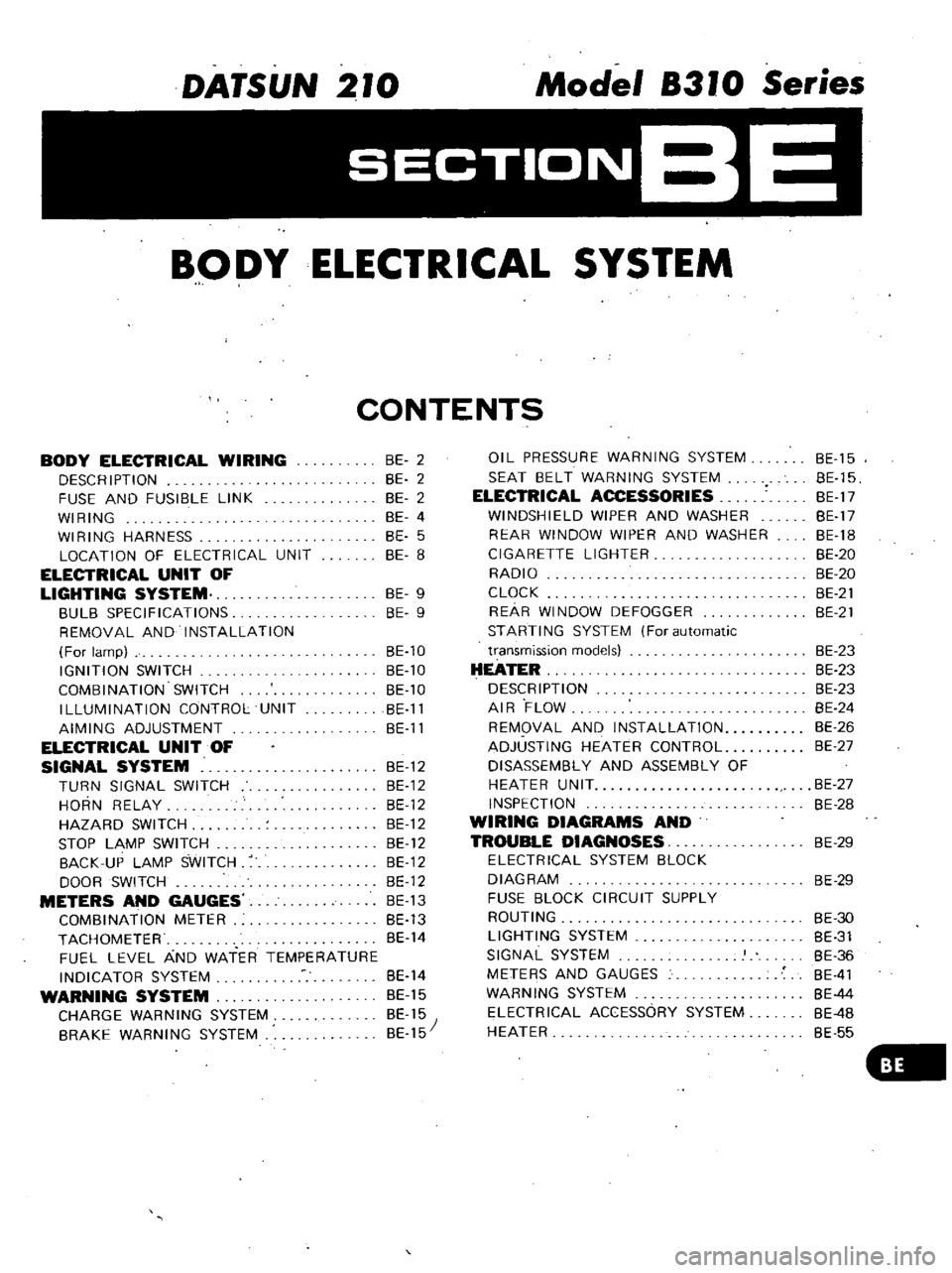
DATSUN
210
Model
8310
Series
SECTIONBE
BODY
ELECTRICAL
SYSTEM
CONTENTS
BODY
ELECTRICAL
WIRING
DESCRIPTION
FUSE
AND
FUSIBLE
LINK
WIRING
WIRING
HARNESS
LOCATION
OF
ELECTRICAL
UNIT
ELECTRICAL
UNIT
OF
LIGHTING
SYSTEM
BULB
SPECIFICATIONS
REMOVAL
AND
INSTALLATION
For
lamp
IGNITION
SWITCH
COMBINATION
SWITCH
ILLUMINATION
CONTROL
UNIT
AIMING
ADJUSTMENT
ELECTRICAL
UNIT
OF
SIGNAL
SYSTEM
BE
12
TURN
SIGNAL
SWITCH
BE
12
HORN
RELAY
BE
12
HAZARD
SWITCH
BE
12
STOP
LAMP
SWITCH
BE
12
BACK
UP
LAMP
SWITCH
BE
12
DOOR
SWITCH
BE
12
METERS
AND
GAUGES
BE
13
COMBINATION
METER
BE
13
TACHOMETER
BE
14
FUEL
LEVEL
AND
WATER
TEMPERATURE
INDICATOR
SYSTEM
BE
14
WARNING
SYSTEM
BE
15
CHARGE
WARNING
SYSTEM
BE
15
BRAKE
WARNING
SYSTEM
BE
15
BE
2
BE
2
BE
2
BE
4
BE
5
BE
8
BE
9
BE
9
BE
10
BE
10
BE
10
BE
11
BE
11
OIL
PRESSURE
WARNING
SYSTEM
SEAT
BELT
WARNING
SYSTEM
ELECTRICAL
ACCESSORIES
WINDSHIELD
WIPER
AND
WASHER
REAR
WINDOW
WIPER
AND
WASHER
CIGARETTE
LIGHTER
RADIO
CLOCK
REAR
WINDOW
DEFOGGER
STARTING
SYSTEM
For
automatic
transmission
models
HEATER
DESCRIPTION
AIR
FLOW
REMOVAL
AND
INSTALLATION
ADJUSTING
HEATER
CONTROL
DISASSEMBLY
AND
ASSEMBLY
OF
HEATER
UNIT
INSPECTION
WIRING
DIAGRAMS
AND
TROUBLE
DIAGNOSES
ELECTRICAL
SYSTEM
BLOCK
DIAGRAM
FUSE
BLOCK
CIRCUIT
SUPPLY
ROUTING
LIGHTING
SYSTEM
SIGNAL
SYSTEM
METERS
AND
GAUGES
WARNING
SYSTEM
ELECTRICAL
ACCESSORY
SYSTEM
HEATER
BE
15
BE
15
BE
17
BE
17
BE
18
BE
20
BE
20
BE
21
BE
21
BE
23
BE
23
BE
23
BE
24
BE
26
BE
27
BE
27
BE
28
BE
29
BE
29
BE
30
BE
31
BE
36
BE
41
BE
44
BE
4B
BE
55
Page 454 of 548
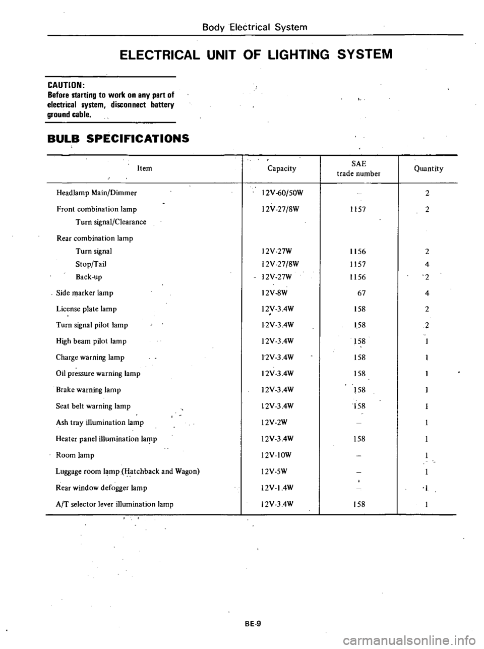
Body
Electrical
System
ELECTRICAL
UNIT
OF
LIGHTING
SYSTEM
CAUTION
Before
starting
to
work
on
any
part
of
electrical
system
disconnect
battery
ground
cable
BULB
SPECIFICATIONS
Item
Headlamp
Main
Dilnmer
Front
combination
lamp
Turn
signal
Clearance
Rear
combination
lamp
Turn
signal
Stop
Tail
Back
up
Side
marker
lamp
License
plate
lamp
Turn
signal
pilot
lamp
High
beam
pilot
lamp
Charge
warning
lamp
Oil
pressure
warning
lamp
Brake
warning
lamp
Seat
belt
warning
lamp
Ash
tray
illumination
lamp
Heater
panel
illumination
laf
lp
Room
lamp
Luggage
room
lamp
Hatchback
and
Wagon
Rear
window
defogger
lamp
AfT
selector
lever
illumination
lamp
Capacity
SAE
trade
number
12V
60
50W
l2V
27
8W
1157
l2V
27W
12V
27
8W
12V
27W
12V
8W
l2V
3
4W
l2V
3
4W
l2V
3
4W
12V
3
4W
12V
3
4W
12V
3
4W
12V
3
4W
l2V2W
l2V
3
4W
l2V
lOW
Quantity
2
2
1156
2
1157
4
1156
2
67
4
158
2
158
2
158
158
158
158
158
158
l2V
5W
12V
14W
12V
3
4W
158
BE
9