fuse diagram DATSUN 210 1979 Service Manual
[x] Cancel search | Manufacturer: DATSUN, Model Year: 1979, Model line: 210, Model: DATSUN 210 1979Pages: 548, PDF Size: 28.66 MB
Page 104 of 548
1
Ignition
switch
2
Amplifier
3
Speed
switch
Note
a
Tightening
torque
is
1
8
to
2
2
kg
m
13
to
16
ft
Ib
b
After
replacement
start
engine
and
check
to
be
sure
that
fuel
is
not
leaking
and
that
anti
dieseling
sole
noid
i
in
good
condition
EFOSOA
Fig
EF47
Checking
Anti
dieaeling
Solenoid
l
SJ
Engine
Fuel
THROTTLE
OPENER
CONTROL
SYSTEM
When
idling
speed
is
too
high
and
does
not
drop
to
idling
speed
the
throttle
opener
control
system
should
be
checked
Manual
transmission
models
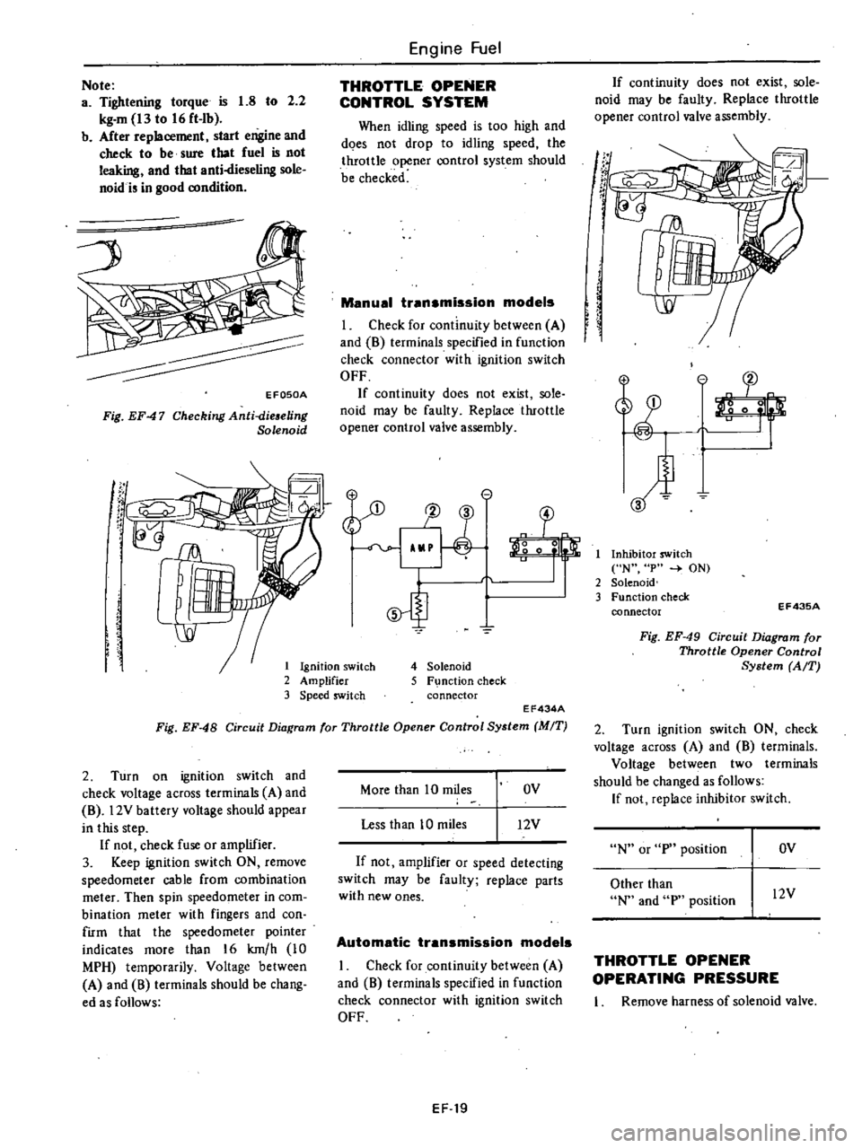
I
Check
for
continuity
between
A
and
8
terminals
specified
in
function
check
connector
with
ignition
switch
OFF
If
continuity
does
not
exist
sole
noid
may
be
faulty
Replace
throttle
opener
control
valve
assembly
e
1J
3
o
0
5
4
Solenoid
5
F
nction
check
connector
EF434A
Fig
EF
48
Circuit
Diagram
for
Throttle
Opener
Control
System
MIT
2
Turn
on
ignition
switch
and
check
voltage
across
terminals
A
and
8
l2V
battery
voltage
should
appear
in
this
step
If
not
check
fuse
or
amplifier
3
Keep
ignition
switch
ON
remove
speedometer
cable
from
combination
meter
Then
spin
speedometer
in
com
bination
meter
with
fingers
and
con
firm
that
the
speedometer
pointer
indicates
more
than
16
km
h
10
MPH
temporarily
Voltage
between
A
and
8
terminals
should
be
chang
ed
as
follows
More
than
10
miles
OV
Less
than
10
miles
12V
If
not
amplifier
or
speed
detecting
switch
may
be
faulty
replace
parts
with
new
ones
Automatic
transmission
models
I
Check
for
continuity
between
A
and
8
terminals
specified
in
function
check
connector
with
ignition
switch
OFF
EF
19
If
continuity
does
not
exist
sole
noid
may
be
faulty
Replace
throttle
opener
control
valve
assembly
If
t
r
If
I
Inhibitor
switch
N
p
ON
2
Solenoid
3
Function
check
connector
EF43SA
Fig
EF
49
Circuit
Diagram
for
Throttle
Opener
Control
System
AfT
2
Turn
ignition
switch
ON
check
voltage
across
A
and
8
terminals
Voltage
between
two
terminals
should
be
changed
as
follows
If
not
replace
inhibitor
switch
N
or
p
position
OV
Other
than
N
and
p
position
l2V
THROTTLE
OPENER
OPERATING
PRESSURE
I
Remove
harness
of
solenoid
valve
Page 446 of 548
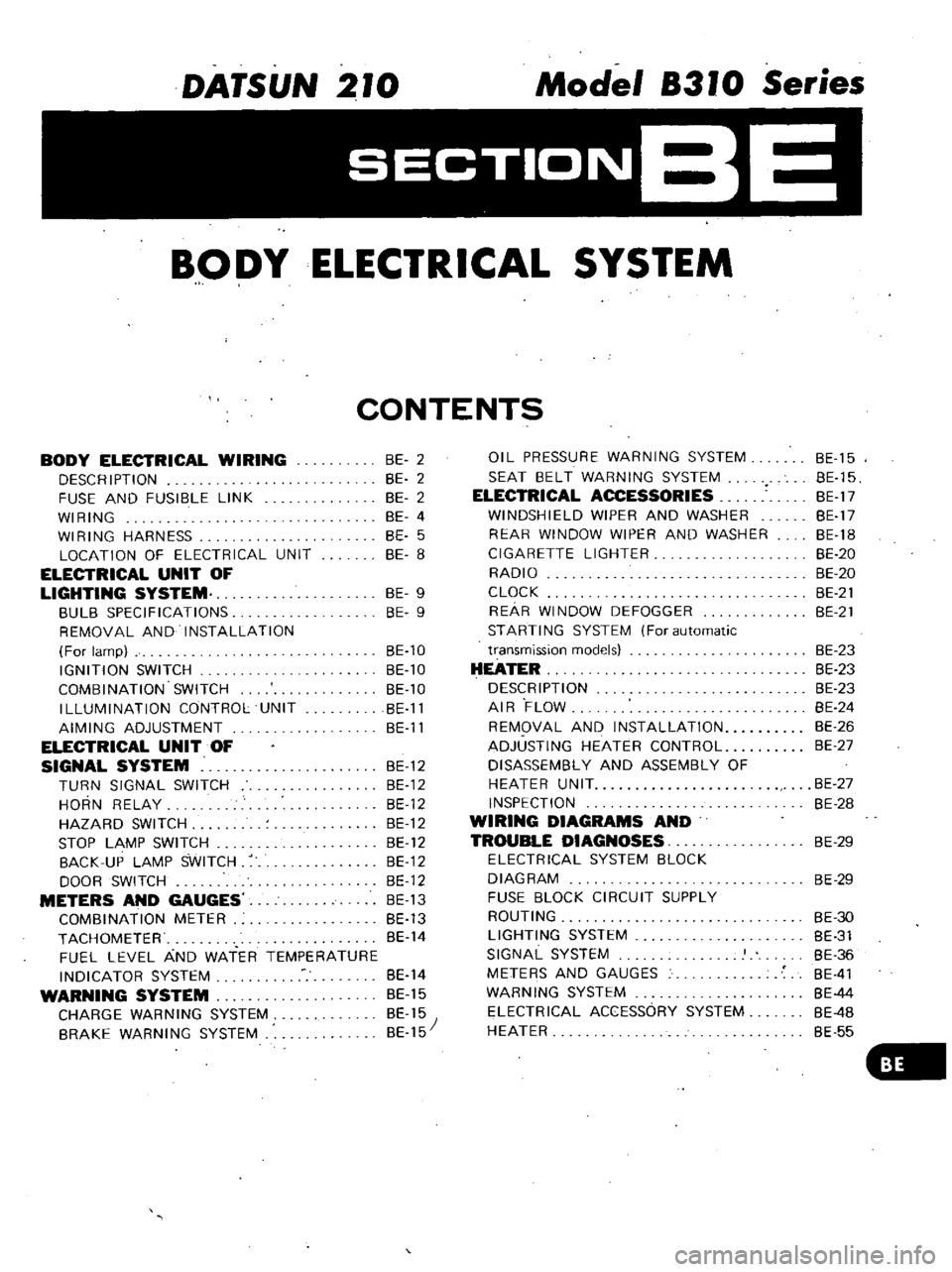
DATSUN
210
Model
8310
Series
SECTIONBE
BODY
ELECTRICAL
SYSTEM
CONTENTS
BODY
ELECTRICAL
WIRING
DESCRIPTION
FUSE
AND
FUSIBLE
LINK
WIRING
WIRING
HARNESS
LOCATION
OF
ELECTRICAL
UNIT
ELECTRICAL
UNIT
OF
LIGHTING
SYSTEM
BULB
SPECIFICATIONS
REMOVAL
AND
INSTALLATION
For
lamp
IGNITION
SWITCH
COMBINATION
SWITCH
ILLUMINATION
CONTROL
UNIT
AIMING
ADJUSTMENT
ELECTRICAL
UNIT
OF
SIGNAL
SYSTEM
BE
12
TURN
SIGNAL
SWITCH
BE
12
HORN
RELAY
BE
12
HAZARD
SWITCH
BE
12
STOP
LAMP
SWITCH
BE
12
BACK
UP
LAMP
SWITCH
BE
12
DOOR
SWITCH
BE
12
METERS
AND
GAUGES
BE
13
COMBINATION
METER
BE
13
TACHOMETER
BE
14
FUEL
LEVEL
AND
WATER
TEMPERATURE
INDICATOR
SYSTEM
BE
14
WARNING
SYSTEM
BE
15
CHARGE
WARNING
SYSTEM
BE
15
BRAKE
WARNING
SYSTEM
BE
15
BE
2
BE
2
BE
2
BE
4
BE
5
BE
8
BE
9
BE
9
BE
10
BE
10
BE
10
BE
11
BE
11
OIL
PRESSURE
WARNING
SYSTEM
SEAT
BELT
WARNING
SYSTEM
ELECTRICAL
ACCESSORIES
WINDSHIELD
WIPER
AND
WASHER
REAR
WINDOW
WIPER
AND
WASHER
CIGARETTE
LIGHTER
RADIO
CLOCK
REAR
WINDOW
DEFOGGER
STARTING
SYSTEM
For
automatic
transmission
models
HEATER
DESCRIPTION
AIR
FLOW
REMOVAL
AND
INSTALLATION
ADJUSTING
HEATER
CONTROL
DISASSEMBLY
AND
ASSEMBLY
OF
HEATER
UNIT
INSPECTION
WIRING
DIAGRAMS
AND
TROUBLE
DIAGNOSES
ELECTRICAL
SYSTEM
BLOCK
DIAGRAM
FUSE
BLOCK
CIRCUIT
SUPPLY
ROUTING
LIGHTING
SYSTEM
SIGNAL
SYSTEM
METERS
AND
GAUGES
WARNING
SYSTEM
ELECTRICAL
ACCESSORY
SYSTEM
HEATER
BE
15
BE
15
BE
17
BE
17
BE
18
BE
20
BE
20
BE
21
BE
21
BE
23
BE
23
BE
23
BE
24
BE
26
BE
27
BE
27
BE
28
BE
29
BE
29
BE
30
BE
31
BE
36
BE
41
BE
44
BE
4B
BE
55
Page 447 of 548
DESCRI
PTI
ON
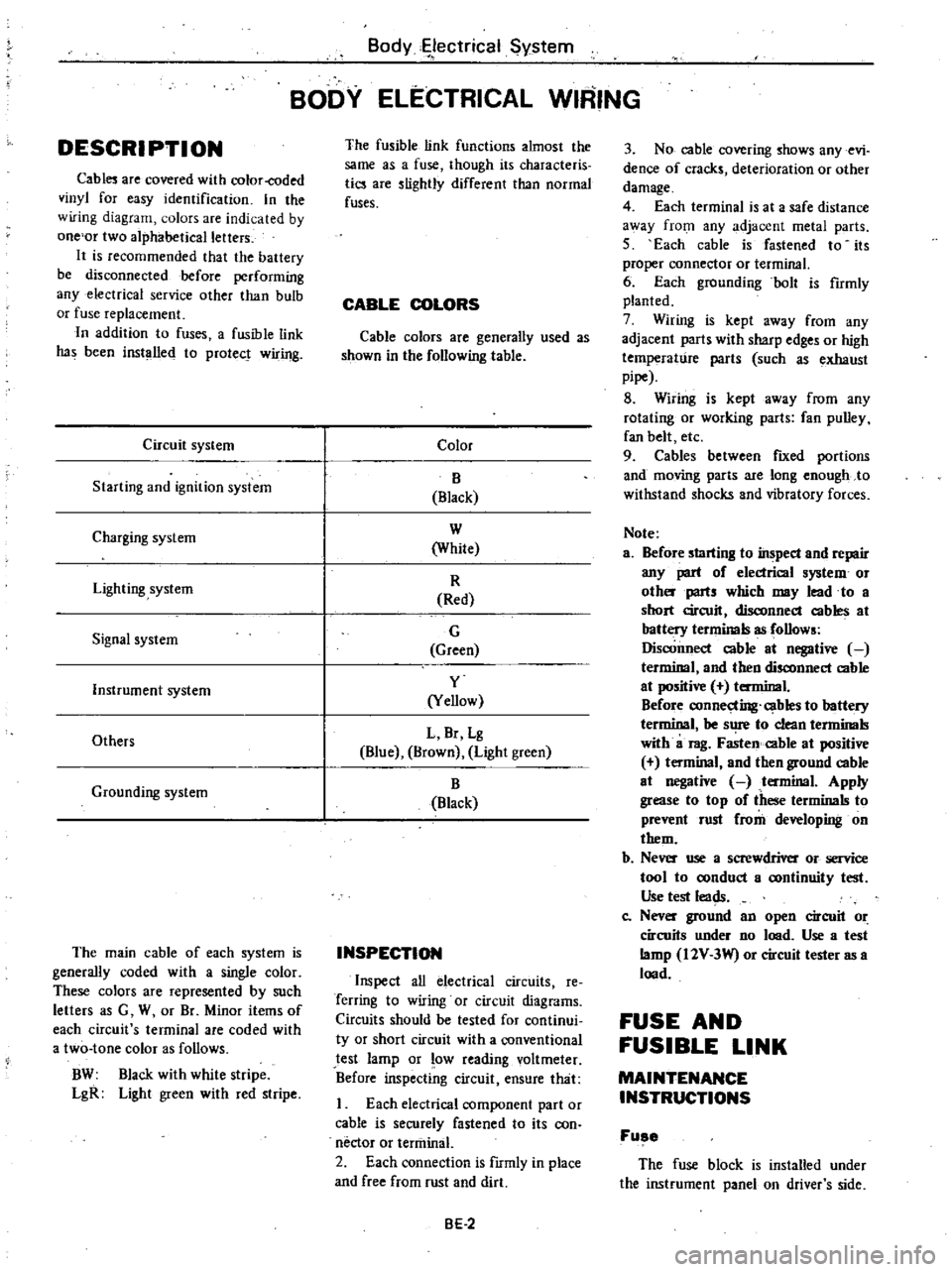
Cabl
are
covered
with
color
coded
vinyl
for
easy
identification
In
the
wiring
diagram
olors
are
indicated
by
one
or
two
alphabetical
letters
It
is
recommended
that
the
battery
be
disconnected
before
performing
any
electrical
service
other
than
bulb
or
fuse
replacement
In
addition
to
fuses
a
fusible
link
has
been
installed
to
protect
wiring
Circuit
system
Starting
and
ignition
system
Charging
system
Lighting
system
Signal
system
Instrument
system
Others
Grounding
system
The
main
cable
of
each
system
is
generally
coded
with
a
single
color
These
colors
are
represented
by
such
letters
as
G
W
or
Br
Minor
items
of
each
circuit
s
terminal
are
coded
with
a
two
tone
color
as
follows
BW
Black
with
white
stripe
LgR
Light
green
with
red
stripe
Body
ectrical
System
BODY
ELECTRICAL
WIRING
The
fusible
link
functions
almost
the
same
as
a
fuse
though
its
characteris
tics
are
slightly
different
than
normal
fuses
CABLE
COLORS
Cable
colors
are
generally
used
as
shown
in
the
following
table
Color
B
Black
W
White
R
Red
G
Green
y
Yellow
L
Br
Lg
Blue
Brown
Light
green
B
Black
INSPECTION
Inspect
all
electrical
circuits
Ie
Terring
to
wiring
or
circuit
diagrams
Circuits
should
be
tested
for
continui
ty
or
short
circuit
with
a
conventional
test
lamp
or
low
reading
voltmeter
Before
inspecting
circuit
ensure
that
I
Each
electrical
component
part
or
cable
is
securely
fastened
to
its
con
nector
or
tenninal
2
Each
connection
is
fIrmly
in
place
and
free
from
rust
and
dirt
BE
2
3
No
cable
covering
shows
any
evi
dence
of
cracks
deterioration
or
other
damage
4
Each
terminal
is
at
a
safe
distance
3
Vay
from
any
adjacent
metal
parts
5
Each
cable
is
fastened
to
its
proper
connector
or
terminal
6
Each
grounding
bolt
is
fumly
planted
7
Wiring
is
kept
away
from
any
adjacent
parts
with
sharp
edges
or
high
temperature
parts
such
as
exhaust
pipe
8
Wiring
is
kept
away
from
any
rotating
or
working
parts
fan
pulley
fan
belt
etc
9
Cables
between
fIXed
portions
and
moving
parts
are
long
enough
to
withstand
shocks
and
vibratory
forces
Note
a
Before
starting
to
inspect
and
repair
any
part
of
electrical
system
or
oth
parts
which
may
lead
to
a
short
circuit
disconnect
cables
at
battery
terminals
as
follows
Disconnect
cable
at
negative
terminal
and
then
disconnect
cable
at
positive
terminal
Before
connecting
cables
to
battery
terminal
be
s
1
to
clean
tenninals
with
a
rag
Fasten
cable
at
positive
t
minal
and
then
ground
cable
at
negative
tenninal
Apply
grease
to
top
of
these
terminals
to
prevent
rust
from
developing
on
them
b
Ne
use
a
screwdriver
or
service
tool
to
oonduct
a
oontinuity
test
Use
test
leads
Co
Nev
ground
an
open
circuit
or
circuits
under
no
lood
Use
a
test
lamp
I2V
3W
or
circuit
tester
as
a
lood
FUSE
AND
FUSIBLE
LINK
MAINTENANCE
INSTRUCTIONS
Fuse
The
fuse
block
is
installed
under
the
instrument
panel
on
driver
s
side
Page 497 of 548
Body
Electrical
System
THEFT
CTlON
SYSTEM
t
o
CALIFORNIA
ANO
BATTERY
FU
MOOELS
G
t
WT
FUSIBGLE
LINK
I
at
L
Q
Q
WRJ
NON
cALlFORNIA
ANO
CANAOA
MOOELS
WARNING
BUZZER
STEERING
n
LOCK
u
SWITCH
U
D
7
RC
JQ
RL
2
2
00
i
r
B
Le
r
RljG
8
RG
FUSE
BLOCK
0
RLel
L
OOOR
ITCH
R
CJ
E
W
BEl580
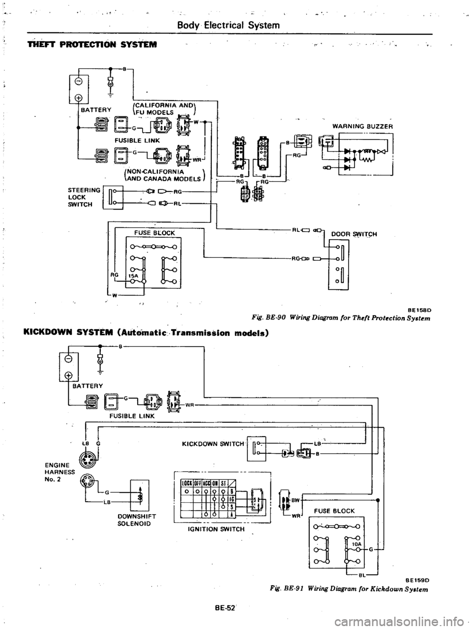
Fig
BE
90
Wiring
Diagram
for
Theft
Protection
Sy
tem
KICKDOWN
SYSTEM
Automatic
Transmission
models
tf
ENGINE
HARNESS
No
2
@
BATTERY
A
G
rT
l
t
1
I
FUSIBLE
LINK
I
I
B
KICKOOWN
SWITCH
rfi
L
1
I
IIIOCI
OIl
ICtOI
Sl
10
009
B
@
I
I
5
li
I
8W
1
Irs
I
0
0
IT
WR
IGNITION
SWITCH
FUSE
BLOCK
OOWNSHIFT
SOLENOIO
0
0
BE1590
Fig
BE
91
Wiring
Diagram
for
Kickdown
Sy
tem
3
C8L
G
BE
52
Page 502 of 548
DATSUN
210
Model
8310
Series
SECTIONAC
AIR
CONDITIONING
CONTENTS
DESCRIPTION
OUTLINE
OF
AIR
CONDITIONER
REFRIGERATION
SYSTEM
AIR
FLOW
VACUUM
SYSTEM
ELECTRICAL
CIRCUIT
GENERAL
SERVICE
REFRIGERANT
R
12
COMPRESSOR
OIL
MAINTENANCE
GENERAL
SERVICE
INSTRUCTIONS
SAFETY
PRECAUTIONS
EVACUATING
AND
CHARGING
SYSTEM
CHECKI
NG
FOR
LEAKS
REFRIGERANT
LEVEL
CHECK
COMPRESSOR
OIL
LEVEL
OHECK
PERFORMANCE
TEST
REFRIGERANT
LEAKS
SERVICE
PROCEDURES
FAST
IDLE
ACTUATOR
IDL
E
PULLEY
AND
COMPRESSOR
DRIVE
BELT
COMPR
ESSOR
CONDENSER
RECEIV
ER
DRIER
REFRIGERANT
LINES
I
COOLING
UNIT
EXPANSION
VALVE
THERMOSTAT
MAIN
RELAY
HEATER
UNIT
WATER
COCK
AC
2
AC
2
AC
3
AC
5
AC
6
AC
7
AC
9
AC
9
AC
9
AC
9
AC
9
AC
9
AC
1
AC14
AC15
AC
17
AC17
AC17
AC18
AC1B
AC19
AC19
AC
20
AC
20
AC
21
ACc21
AC
22
AC
22
AC
23
AC
23
AC
23
BLOWER
MOTOR
RESISTOR
AIR
CONDITIONER
CONTROL
FAN
SWITCH
MICROSWITCH
LOW
PRESSURE
SWITCH
MAGNET
VALVE
FUSE
REPLACEMENT
VACUUM
HOSE
DIAGRAM
WIRING
DIAGRAM
COMPRESSOR
MODEL
SC206
PRELIMINARY
CLEANING
COMPRESSOR
CLUTCH
SHAFT
SEAL
CYLINDER
HEAD
AND
VALVE
PLATE
DISCHARGE
AND
sU
CTiON
CONNECTORS
TROUBLE
DIAGNOSES
AND
CORRECTIONS
AIR
CONDITIONER
DIAGNOSES
BLOWER
MOTOR
DIAGNOSES
COMPRESSOR
DIAGNOSES
COMPRESSOR
CLUTCH
DIAGNOSES
VACUUM
SYSTEM
DIAGNOSES
PERFORMANCE
TEST
DIAGNOSES
PERFORMANCE
CHART
SERVICE
DATA
AND
SPECIFICATIONS
GENERAL
SPECIFICATIONS
INSPECTION
AND
ADJUSTMENT
TIGHTENING
TORQUE
SPECIAL
SERVICE
TOOLS
AC
23
AC
23
AC
23
AC
23
AC23
AC
24
AC
24
AC24
AC
24
AC
25
AC
26
AC
27
AC
27
AC
28
AC30
AC30
AC32
AC
32
AC
33
AC34
AC35
AC36
AC37
AC
41
AC
42
AC
42
AC
42
AC
43
AC
44
Page 508 of 548
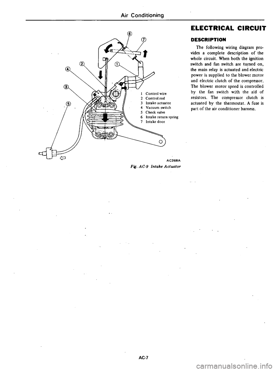
Air
Conditioning
4
1
Control
wire
2
Control
rod
3
Intake
actuator
4
Vacuum
switch
5
Check
valve
6
Intake
return
spring
7
Intake
door
AC268A
Fig
AC
9
Intake
Actuator
AC
7
ELECTRICAL
CIRCUIT
DESCRIPTION
The
following
wiring
diagram
pro
vides
a
complete
description
of
the
whole
circuit
When
both
the
ignition
switch
and
fan
switch
are
tu
ned
on
the
main
relay
is
actuated
and
electric
power
is
supplied
to
the
blower
motor
and
electric
clutch
of
the
compressor
The
blower
motor
speed
is
controlled
by
the
fan
switch
with
the
aid
of
resistors
The
compressor
clutch
is
actuated
by
the
thermostat
A
fuse
is
part
of
the
air
conditioner
harness
Page 525 of 548
LOW
PRESSURE
SWITCH
REMOVAL
AND
INSTALLATION
I
Disconnect
battery
ground
cable
2
Discharge
refrigerant
from
sys
tem
Refer
to
General
Service
3
Disconnect
connector
to
low
pressure
switch
4
Remove
low
pressure
switch
by
turning
the
switch
5
Installation
is
in
the
reverse
order
of
removal
INSPECTION
Using
a
circuit
tester
make
sure
that
low
pressure
switch
exhibits
con
tinuity
when
gas
pressure
of
refriger
ant
in
system
is
normal
and
that
low
pressure
switch
does
not
exhibit
con
tinuity
when
gas
pressure
drops
below
2
2
kg
cm2
31
p
i
MAGNET
VALVE
REMOVAL
AND
INSTALLATION
I
Disconnect
battery
ground
cable
2
Disconnect
magnet
valve
lead
wires
and
vacuum
hoses
3
Remove
magnet
valve
securing
screws
and
then
remove
magnet
valve
i
i
WrE
AC389A
Fig
AC
36
Removjng
Magnet
Valve
4
Installation
is
in
the
reverse
order
of
removal
INSPECTION
I
rest
continuity
with
ohmmeter
2
Apply
D
C
12
volts
across
termi
Air
Conditioning
031
under
this
state
orally
blow
through
one
vacuum
port
to
ensure
that
there
is
air
flow
at
the
other
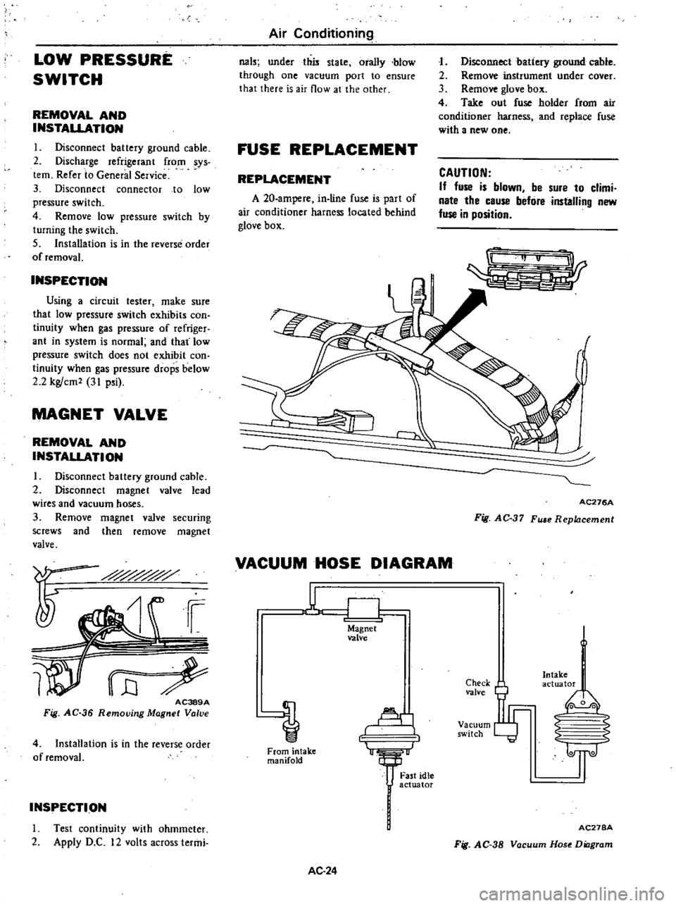
FUSE
REPLACEMENT
REPLACEMENT
A
20
ampere
in
line
fuse
is
part
of
air
conditioner
harness
located
behind
glove
box
J
Disconnect
batiery
ground
cable
2
Remove
instrument
under
cover
3
Remove
glove
box
4
Take
out
fuse
holder
from
air
conditioner
harness
and
replace
fuse
with
a
new
one
CAUTION
If
fuse
is
blown
be
sure
to
climi
nate
the
cause
befure
installing
new
fuse
in
position
r
AC276A
Fig
AC
37
Fu
e
Replacement
VACUUM
HOSE
DIAGRAM
u
CJ
Magnet
valve
Al
1
From
intake
manifold
AC
24
Fast
idle
actuator
Check
valve
Vacuum
switch
Intake
actuator
I
0
0
2
S
1l
AC27BA
Fig
AC
38
Vacuum
Hose
Diagram
Page 526 of 548
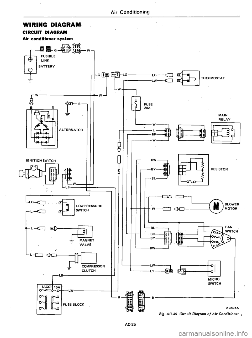
WIRING
DIAGRAM
CIRCUIT
DIAGRAM
Air
conditioner
system
G
DD
w
FUSIBLE
LINK
I
BATTERY
LG
Lr
LG
c
J
LW
J
I
THERMOSTAT
W
W
r
B
B
8
ALTERNATOR
IGNITION
SWITCH
il
W
LB
LLG
J
LOW
PRESSURE
SWITCH
L
c
J
L
c
J
l
J
MAGNET
VALVE
L
c
J
CJ
C
COMPRE
SOR
CLUTCH
LIT
IACC
15A
L1
3
E
FUSE
BLOCK
Air
Conditioning
W
1
8
t
FUSE
20A
MAIN
RELAY
J
rn
W
I
fJ
RESISTOR
Dt
J
M
BLOWER
MOTOR
W
c
J
c
J
C
r
BvM
LW
LY
I
MICRO
SWITCH
B
AC404A
Fig
AC
39
Circuit
Diagram
of
Air
Conditioner
I
AC
25
Page 546 of 548
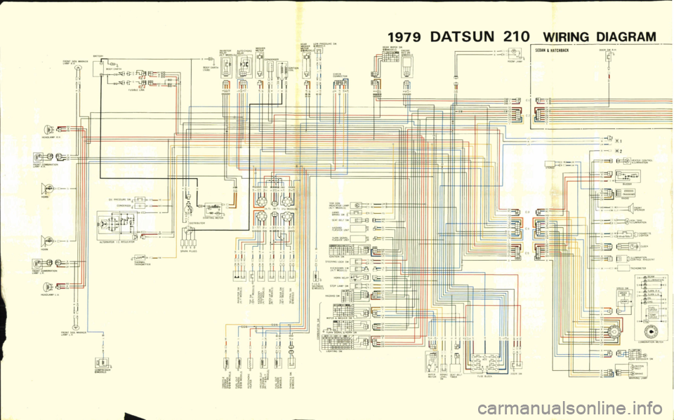
J
E
HEA
DLAMPIlH
fRQNT
COMO
uION
lAMP
IlH
c
D
HORN
I
fIlONTCOHIB
ATION
lAMPLH
Z
I
HEADLAMP
lH
fIlO
SlOE
MAIlKEII
l
PIIH
II
i
Jl
fllONT
SIDE
MARKER
LAMP
lH
BATTERY
fl
d
Wi
1
f
FUSlBlElINI
J
CO
OENSEII
C
Il
LrEFlhATOR
litn
J
HiERMM
TIlANSMITTUi
j
m
COMPIIESSO
MOOELS
BOOVU
1l1H
SUB
L
J
DISTIlIBUTOR
SPAllA
PLUGS
0
0
Ii
0
t
E
i
w
a
E
g
8
J
0
w
u
g
r
I
J
j
H
U
oo
i@
5
2
@
Ww
W
W
ai
o
ww
i
woO
a
i
Jwt
o
o
2
0
i
i
52
1
w
0
JwO
WJ
1979
FILAR
WIPEIl
SW
I
g
aml
ffll
CD
1o
i
CHECK
CONNECTOR
m
TOROON
r
O
L
GW
f
nttJ
p
ar
G
HAND
G
BIl
IUSW
SE
u
am
sw
J8
eI
8
HAZ
IlD
n
Gl
flASHER
UNITL
Y
G
TUIlN5IGN
l
flASHEIlUN
O
ow
w
IGHIIION
SW
LO
STEERINGlOCIISW
KICKOOWNSW
r
Ol
0
1
DOHS
L
d
CJ
CJ
R
I
I
STOPlAIOIP
SW
c
L
J
d
q
c
m
HAZARDSW
g
L
WIPER
WASHEII
SW
r
o
IIE
lURN
SlGNAl
HOIlN
SW
iE
lIGHTING
SW
DATSUN
210
I
II
I
W
PEII
BIIAIIE
SEAl
BEll
IoIOIOR
LEVU
TI
ElI
w
FUSE
BlOC
6
DJ
liDO
LAMP
W
l
l
HlP
i
1
iY
ow
0
L
ill
iJUlf
1IE
l1l
WWPIIESSUIIE
SW
WASHEII
MODElS
1f
II
Wm
I
TI
U
jJ
rm
fII
91n
l
j
Ii
W
I
w
j
S
e
000
Sv
WIRING
DIAGRAM
SEDAN
HATCHBACK
i
I
ow
ow
f
I
GiD
1
2
w
F
w
0
Wt
f
F
fo
e
l
lL
9
rr
hS
lHlAlllI
CONllIOl
lllUIOI
NATI
lI
I
i
l1iKiI
l
w
ijij
ijf
r
r
10
o
mm
WI
llj
H
n
lJ
6
Jffi
@
Fie
D
SOLENOID
1
IoIODElS
C3
t
11
I
lG
lG
B
LII
W
W
C
c
G
G
GY
0
I
Ii
II
I
BUZZEll
m
lm
1
RADIO
rj
S
J
F
OHI
cJD
L
SPEAKE
G
J
ASHT
AT
G
c
lllU
NATI
N
Gl
J
C
GAIIE11
R
J
UGHI
Gs
JTn
fllU
ATIl
r
CO
IlDLIIHEOSTA
J
aa
TAC
lllI
Jo
l
lAr
hI
4
I
TIINIIH
TUIINll1
3E1
I
o
G8
J
ReO
ow
0
COhlBIN
TI
NlIIHER
Il
IILO
II
DHOGGEII
sw
1
P
Page 547 of 548
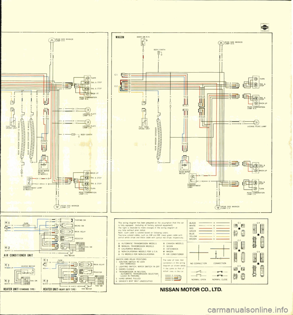
C
E3J
i
I
u
r
o
alNATIO
1
9
fl
l
w
tif
S
lATr
u
N
T
i
0
lf
5f
lAH
8
g
llOOY
AIITI
0
BI
b
RWIPER
IoOODELS
a
RW
LUGGAGf
aD
B
iO
b
n
rNr
lAMP
1
FUSE
1
AIR
CONDnION
R
UNIT
1
lii
I
I
N
UNITCSlAMD
UOTYPEl
I
LAMP
lH
ARKER
Th
ng
diagram
ha
been
fullyeqU1pped
nclod
p
wredontheas
The
ght
IS
e
erv
l
og
all
factory
optIonal
SUmQtron
tllat
the
car
BLACK
any
tme
II
1aut
to
make
chang
s
In
the
eQU
Omefll
Note
EaCh
cao
ro
notICe
l
d
g
am
at
WHITE
D
CI
r
olon
colO
E
d
Ca
Iore
l
ba
ed
on
1011010
ffi
El3
C4
pa
l
a
wh
te
Sl
l
bles
Suel
as
GW
n
8R
g
colors
GREEN
1m
o11Id
blaCk
cao
th
pa
l
I
n
5
at
l@
Il
BLUE
C
AUTOMATIC
fRAN
pe
l
tely
YlilOW
I
MANUAL
TRAN
M
MISSION
MODUS
BROWN
1
CALIFORNIA
MOD
ION
MODELS
A
MODELS
w
w
B
j
NONCAUroRNIA
I
HATCHBACK
It
it
FU
MODEtS
FOR
tS
FOR
USA
WAGON
AllFORN
A
t
AIR
CONDITIONER
SWITCH
AND
RE
J
IGNITION
SWI
Y
POSITIONS
KEY
REMOVEO
IN
lOCII
n
co
o
011
@
1
1
LIGHTING
SWITCH
W
P
con
10
lhe
w
n
g
DOORS
CtoSlO
ER
SWITCH
IN
OFF
TRANSMISSION
m
hown
be
w
NO
CONNECTION
CONNECTION
AUtOMATIC
T
EUTRAl
I
me
th
of
lEVER
IN
PAIU
IN
SSIDN
SlLECfORi
oKlualhne
nthec
HANOBRAIIEPUllEO
t
ffi
III
fi
ORIVEWS
SEAT
BELT
UNOCCUPIED
@
C
JiOR
lOPEN
NORMAL
CLOSE
NISSAN
MOTOR
tl
J
w
iJ
j
II
C
TA
l
SfOP
t
o
L
SlOP
fUPN
lj
ro
elNA
TI
N
JbtJ
1
G
J
W
1
J
ITHERMO
sw
B
H
IMICRO
sw
1
l
n
MA
IN
RELA
V
c
1W231
rAN
SW
I
A
NMOTOR
of
l
I
rr
I
I
I
c
1m231
i
11
II
i
HEATER
UNIT
Mun
DUT
FA
N
J
WAGON
t
o
a
ijE
c
r
g
E3J
FUEl
Tjl
NII
GA
LJGE
UNIT
JL
OODfi
11
tl
DJ
H
t
ow
J
TA
l
BA
CII
UP
rI
O
BlNjl
TIOf
l
J
9
111
fi
l
JID
l
6
o
o
c
II
LICENSE
PLA
TE
LAMP
ijf
I
LUGGAGE
R
r2
ARTMENI
C
ow
Tjl
ll
STOP
IIA
CIIUP
t
C
co
STOP
fURN
n
ro
fBINA
TION
I
J
CO
LTD