remote start DATSUN 210 1979 Service Manual
[x] Cancel search | Manufacturer: DATSUN, Model Year: 1979, Model line: 210, Model: DATSUN 210 1979Pages: 548, PDF Size: 28.66 MB
Page 292 of 548

Place
the
vehicle
in
a
pit
and
by
sampling
the
lealeed
oil
deiermine
if
it
is
the
torque
converter
oil
The
torque
converter
oil
has
a
color
like
red
wine
so
it
is
easily
distinguished
from
engine
oil
or
gear
oil
Wipe
off
the
lealeing
oil
and
dust
and
detect
the
spot
of
ill
lell8e
nonflammable
organic
solvent
such
as
carbon
tetrachloride
for
wiping
Raise
the
oil
tcmperature
by
op
erating
the
engine
and
shift
the
lever
to
D
to
increase
the
oil
pressure
The
sp
Q
of
o
1
1I8
u
J1en
be
found
more
easily
Note
As
oil
leakage
from
the
breath
er
does
not
talee
place
except
when
running
at
high
peed
it
iSimpos
sible
to
ate
this
lealcage
with
vehicle
stationary
CHECKING
ENGINE
IDLING
REVOLunON
The
engine
idling
revolution
should
be
properly
adjusted
If
the
engine
revolution
is
too
low
the
e
gine
does
not
operate
smoothly
and
if
too
high
a
strong
shocle
or
creep
develops
when
changing
over
from
ON
to
Dn
or
R
CHECKING
AND
ADJUSTING
KICK
WN
SWITCH
AND
DOWNSH
FT
SOLENOID
When
the
Ieickdown
operation
is
not
made
properly
or
the
speed
chang
ingpoint
is
too
high
check
the
kick
down
switch
downshift
solenoid
and
wiring
between
them
When
the
igni
tion
Ieey
is
po
iti
ned
at
the
1st
stage
and
the
accelerator
pedal
is
depressed
deeply
the
switch
contact
hould
be
closed
and
the
solenoid
should
clicle
If
it
does
not
click
it
indicates
a
defect
Then
check
each
part
with
the
testing
inatrumen15
Auto
lT1atic
Transmissiqn
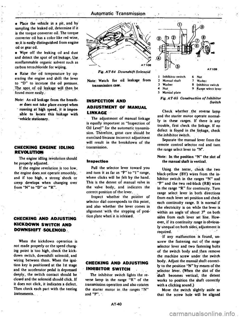
Fi
J
A
T
84
Down
ltift
Sole
id
Note
Watch
for
oil
leekage
from
tnnsmission
case
INSPECTION
AND
ADJUSTMENT
OF
MANUAL
LINKAGE
The
adjustmcnt
of
manual
linkage
i
equany
important
as
Inspection
of
Oil
Level
for
the
automatic
transmis
sion
Therefore
great
care
should
be
cxercised
oecause
incorrect
adjustment
will
result
in
the
breakdown
of
the
transmission
Inspection
pun
the
selector
lever
toward
you
and
turn
it
as
far
as
p
to
range
where
clicks
will
be
ell
by
the
hand
This
is
the
detent
of
manual
valve
in
the
valve
body
and
indicates
the
corrett
position
of
the
lever
Inspect
whether
the
pointer
of
selector
dial
corresponds
to
this
point
and
also
whether
the
lever
comes
in
alignment
with
the
stepping
of
posi
iion
plate
when
itis
released
CHECKING
AND
ADJUSTING
INHIBITOR
SWITCH
The
inhibitor
switch
lights
the
re
verse
lamp
in
the
range
R
of
the
transmission
operation
and
also
rotates
the
starter
motor
in
the
ranges
N
and
P
AT
40
i
j
tI
IlV
@
@
AT
I
Inhibitor
switch
2
Manual
shaft
3
Washer
4
Nut
5
Manual
plate
Fi
J
AT
85
Comtruction
of
Inhibitor
Switch
6
Nut
1
Washer
8
Inhibitor
wilch
9
Ran
q
Iect
lever
Check
w
ethcr
he
leverse
lal
1p
and
the
starter
motor
operate
nonnal
Iy
in
these
ranges
If
there
is
any
trouble
first
check
the
inkage
If
no
defect
is
fo
nd
in
the
Ii
leage
check
tlie
inhibitor
Swi
ch
Separate
the
manual
lever
from
the
remote
control
selector
rod
and
turn
the
range
select
lever
to
N
Note
In
the
position
N
the
slot
of
the
manual
shaft
is
vertical
Using
the
tester
check
the
two
black
yellow
BY
wire
from
the
in
hibitor
switch
in
the
ranges
N
and
p
and
the
two
red
blacle
RB
wires
in
the
lange
R
for
continuity
Turn
range
select
lever
in
both
directions
from
each
lever
set
position
and
check
each
continuity
range
It
is
normal
if
the
electricity
is
on
while
the
lever
is
within
an
angle
of
about
30
on
both
sides
from
each
lever
set
line
How
ever
if
its
continuity
range
is
obvioUs
ly
u
nequal
on
both
sides
adjustment
is
required
If
any
malfunction
is
found
un
screw
the
fastening
nut
o
the
range
selector
lever
and
two
fastening
bolts
of
the
switch
body
and
then
remove
the
machine
screw
under
the
switch
body
Adjust
the
manual
shaft
correct
Iy
to
the
position
N
by
means
of
the
selector
leVer
When
the
slot
of
the
shaft
becomes
vertical
the
detent
worles
to
position
the
shaft
correctly
with
a
clicking
sound
Move
the
switch
slightly
aside
so
that
the
scie
hole
will
be
aligned