reset DATSUN 210 1979 Service Manual
[x] Cancel search | Manufacturer: DATSUN, Model Year: 1979, Model line: 210, Model: DATSUN 210 1979Pages: 548, PDF Size: 28.66 MB
Page 187 of 548

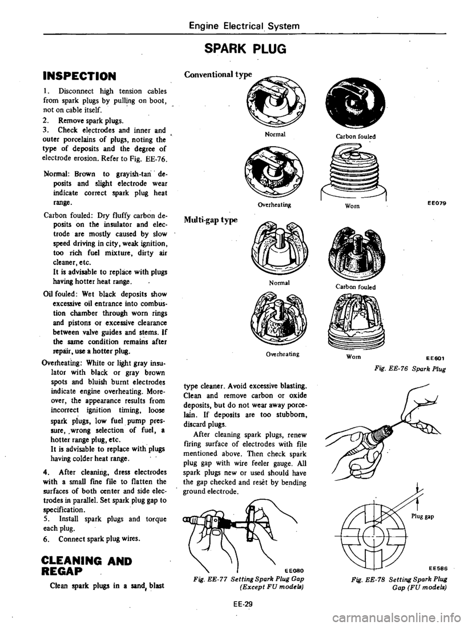
INSPECTION
I
Disconnect
high
tension
cables
from
spark
plugs
by
pulling
on
boot
not
on
cable
itself
2
Remove
spark
plugs
3
Check
electrodes
and
inner
and
outer
porcelains
of
plugs
noting
the
type
of
deposits
and
the
degree
of
electrode
erosion
Refer
to
Fig
EE
76
Normal
Brown
to
grayish
Ian
de
posits
and
slighl
electrode
wear
indicate
correct
spark
plug
heat
range
Carbon
fouled
Dry
fluffy
carbon
de
posits
on
the
insulator
and
elec
trode
are
mostly
caused
by
slow
speed
driving
in
city
weak
ignition
too
rich
fuel
mixture
dirty
air
cleaner
etc
H
is
advisable
to
replace
with
plugs
having
hotter
heat
range
Oil
fouled
Wet
black
deposits
show
excessive
oil
entrance
into
comb
us
tion
chamber
through
worn
rings
and
pistons
or
excessive
clearance
between
valve
guides
and
stems
If
the
same
condition
remains
after
repair
use
a
hotter
plug
Overheating
White
or
light
gray
insu
lator
with
black
or
gray
brown
spots
and
bluish
burnt
electrodes
indicate
engine
overheating
More
over
the
appearance
results
from
incorrect
ignition
timing
loose
spark
plugs
low
fuel
pump
pres
sure
wrong
selection
of
fuel
a
hotter
range
plug
etc
H
is
advisable
to
replace
with
plugs
having
colder
heat
range
4
After
cleaning
dress
electrodes
with
a
smaU
fme
file
to
flatten
the
surfaces
of
both
center
and
side
elec
trodes
in
parallel
Set
spark
plug
gap
to
specification
5
Install
spark
plugs
and
torque
each
plug
6
Connect
spark
plug
wires
CLEANING
AND
REGAP
Clean
spark
plugs
in
a
sand
blast
Engine
Electrical
System
SPARK
PLUG
Conventional
type
Normal
Overheating
Multi
gap
type
Nonnal
Overheating
type
cleaner
Avoid
excessive
blasting
Clean
and
remove
carbon
or
oxide
deposits
but
do
not
wear
away
porce
lain
If
deposits
are
too
stubborn
discard
plugs
After
cleaning
spark
plugs
renew
firing
surface
of
electrodes
with
file
mentioned
above
Then
check
spark
plug
gap
with
wire
feeler
gauge
All
spark
plugs
new
or
used
should
have
the
gap
checked
and
reset
by
bending
ground
electrode
EEOSO
Fig
EE
77
Setting
Spark
Plug
Gap
Except
FU
model
EE
29
Carbon
fouled
EE079
Worn
Carbon
fouled
Worn
EE601
Fig
EE
76
Spark
Plug
EE586
Fig
EE
78
Setting
Spark
Plug
Gap
FU
models
Page 325 of 548

Fig
FA
3
Installing
Coller
Pin
II
Install
hub
cap
with
new
Q
ring
and
wheel
WHEEL
ALIGNMENT
Correct
front
wheel
alignment
as
sures
proper
car
handling
characteris
tics
and
minimum
steering
effort
with
the
least
amount
of
tire
wear
Before
adjusting
front
wheel
alignment
be
sure
to
make
preliminary
inspection
of
front
end
parts
Tire
pressure
and
balance
Wheel
bearings
and
wheel
bearing
nuts
Steering
gear
play
Steering
gear
housing
loose
at
frame
Steering
linkage
and
connections
Shock
absorber
operation
If
wrong
repair
or
replace
the
damaged
portion
or
parts
When
using
equipment
for
front
wheel
alignment
inspection
follow
the
instructions
furnished
with
equipment
Note
Inspection
should
be
made
with
the
car
set
Ievel
and
at
curb
weight
Cember
end
caster
Camber
and
caster
are
preset
at
factory
and
cannot
be
adjusted
The
car
requires
only
toe
in
and
car
posture
adjustment
Note
If
camber
or
caster
alignment
is
not
within
specifications
check
as
sociated
parts
Repair
or
replace
as
necessary
Front
Axle
Front
Suspension
Toe
In
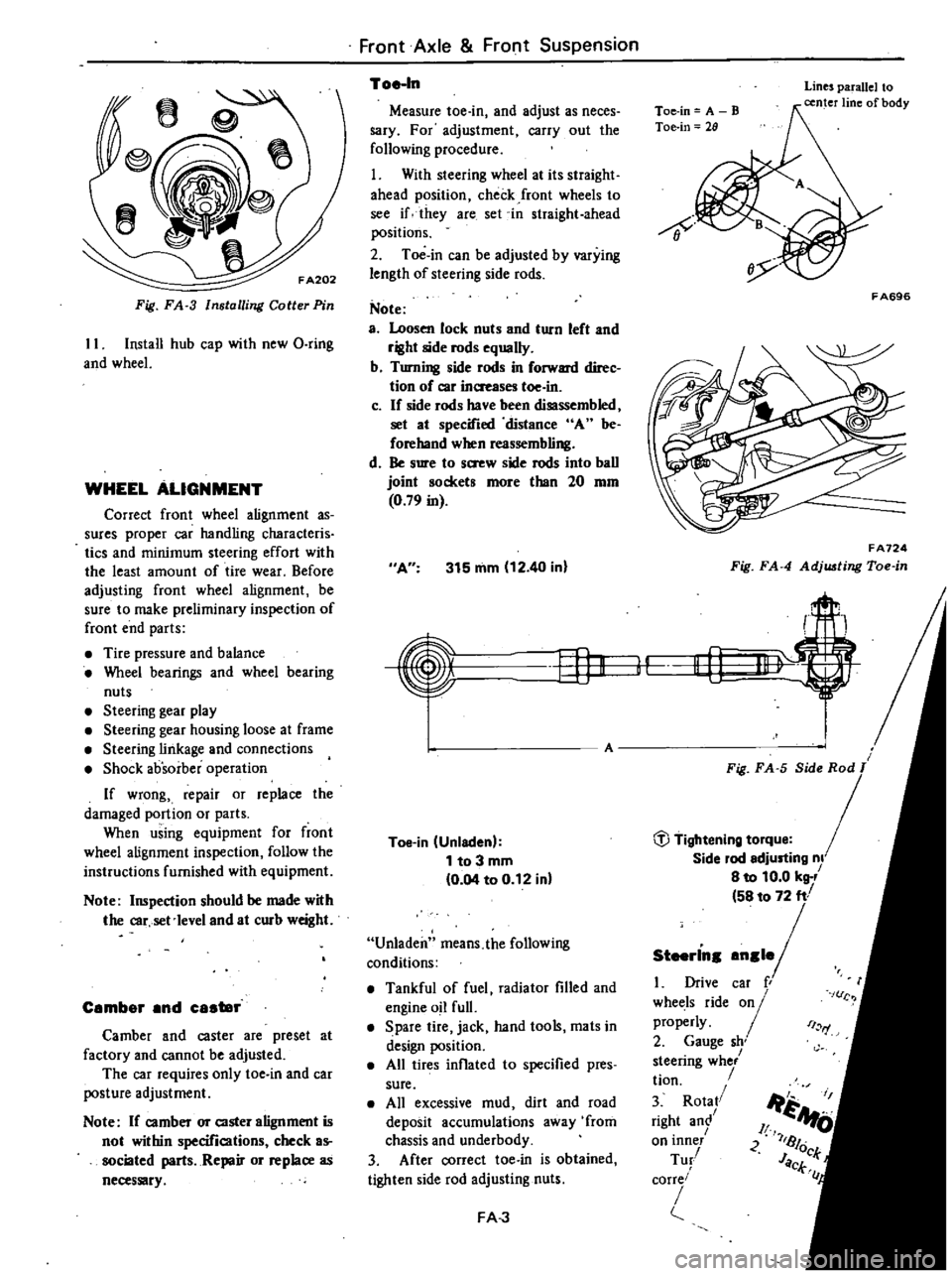
Measure
toe
in
and
adjust
as
neces
sary
For
adjustment
carry
out
the
following
procedure
1
With
steering
wheel
at
its
straight
ahead
position
check
front
wheels
to
see
if
they
are
set
in
straight
ahead
positions
2
Toe
in
can
be
adjusted
by
varying
length
of
steering
side
rods
Note
a
Loosen
lock
nuts
and
turn
left
and
right
side
rods
equally
b
Turning
side
rods
in
forward
direc
tion
of
car
inaeases
toe
in
c
If
side
rods
have
been
disassembled
set
at
specified
distance
A
be
forehand
when
reassembling
d
Be
sure
to
s
w
side
rods
into
ball
joint
sockets
more
than
20
mm
0
79
in
A
315
mm
12
40
in
EfJK
Toe
in
Unladen
1
to
3
mm
0
04
to
0
12
in
Unladen
means
the
following
conditions
Tankful
of
fuel
radiator
filled
and
engine
oil
full
Spare
tire
jack
hand
tools
mats
in
design
position
All
tires
inflated
to
specified
pres
sure
All
excessive
mud
dirt
and
road
deposit
accumulations
away
from
chassis
and
underbody
3
After
correct
toe
in
is
obtained
tighten
side
rod
adjusting
nuts
FA
J
Toe
in
A
B
Toe
in
28
Lines
parallel
to
center
line
of
body
8
F
A696
FA724
Fig
FA
4
Adj
ting
Toe
in
r
II
Li
1
t
Fig
FA
5
Side
Rod
T
Side
lod
edjusting
nl
8
to
10
0
kg
58
to
72
ft
1
Drive
caf
r
whet
ls
ride
01
properly
2
Gauge
sh
steenng
whe
tion
3
Rota
right
an
on
lOner
Tu
corre
i
I
rf
c
Ji
1
A
JI
U
2
7181
JOck
CL
C
Page 459 of 548

Body
Electrical
System
DISASsEMlU
Y
AND
ASSEI
t18LV
BE126D
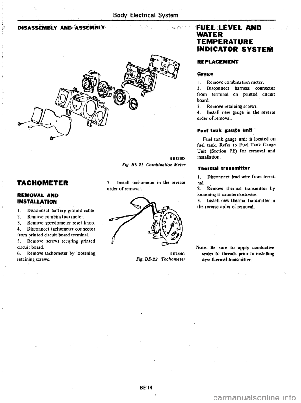
Fig
BE
21
Combination
Meter
TACHOMETER
7
Install
tachometer
in
the
reverse
order
of
removal
REMOVAL
AND
INSTALLATION
I
Disconnect
battery
ground
cable
2
Remove
combination
meter
3
RemO
e
speedometer
reset
knob
4
Disconnect
tachometer
connector
from
printed
circuit
board
terminal
5
Remove
screws
securing
printed
circui
t
board
6
Remove
tachometer
by
loosening
retaining
screws
BE744C
Fig
BE
22
Tachometer
BE
14
FUE
LEVELAND
WATER
TEMPERATURE
INDICATOR
SYSTEM
REPLACEMENT
G11l1ge
I
Remove
combination
meter
2
Disconnect
harness
connector
from
terminal
on
printed
circuit
board
3
Remove
retaining
screws
4
Install
new
gauge
in
the
reverse
order
of
removal
Fuel
tank
gauge
unit
Fuel
tank
gauge
unit
is
located
on
fuel
tank
Refer
to
Fuel
Tank
Gauge
Unit
Section
FE
for
removal
and
installation
Thermal
transmitter
I
Disconnect
lead
wire
from
termi
naL
2
Remove
thermal
transmitter
by
loosening
it
oountercIockwise
3
Install
new
thermal
transmitter
in
the
reverse
order
of
removal
Note
Be
aure
to
apply
conductive
sealer
to
threads
prior
to
installing
new
hennal
transmitter