torque DATSUN 210 1979 Service Manual
[x] Cancel search | Manufacturer: DATSUN, Model Year: 1979, Model line: 210, Model: DATSUN 210 1979Pages: 548, PDF Size: 28.66 MB
Page 9 of 548
Erigine
crankcase
EI
gine
cooling
system
Transmission
case
Final
drive
case
housing
Steering
gear
box
Fuel
tank
Air
conditioning
system
Refrigerant
Compressor
oil
f
tl
It
J
4
i
1
protect
the
catalytic
cop
verter
froitr
contamination
t
n
General
Information
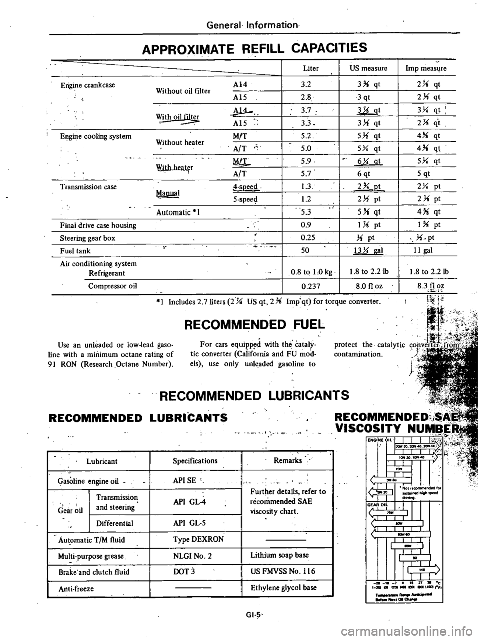
APPROXIMATE
REFILL
CAPACITIES
Without
oil
filter
AI4
Al5
w
Al5
M
T
AfT
MiL
A
T
Liter
US
measure
3
2
3
qt
2
8
3
qt
3
7
llLgt
33
3
qt
5
2
5
qt
5
0
5Y
qt
5
9
6
Y
at
57
6qt
1
3
2
Y
ot
1
2
2
pt
53
5
qt
0
9
1
pt
0
25
pt
50
13
Y
I
0
8
tol
Okg
1
8
to
2
2
1b
0
237
8
0
floz
Withoil
Without
heater
With
heatfr
MaDllal
soeed
5
spee
Automatic
1
1
Includes
2
7
liters
2
US
qt
2
Imp
qt
for
torque
converter
RECOMMENDED
FUEL
Use
an
unleaded
or
low
lead
gaso
line
with
a
minimum
octane
rating
of
91
RON
Research
Octane
Number
For
cars
equipp
d
with
the
Cataly
tic
converter
California
and
FU
mod
els
use
only
unleaded
gasoline
to
RECOMMENDED
Lubricant
GasOline
engine
oil
Gear
oil
Transmission
and
steering
Differential
Au
omatic
TIM
fluid
Multi
purpose
grease
Brake
and
clutch
fluid
Anti
freeze
L
NDED
LUBRICAN
COMMENDED
i
I
VISCOSITY
NUMBER
t1
NGON
0
L
J
I
j
H
I
IlL
I
t
l
I
lc
30
ItM
7
l
t
U
I
ItM
I
L
L
tJ
30
I
I
fu
JIl
inld
do
o
II
L
liOwl
1
I
I
1
10
I
I
I
I
t
I
I
j
r
I
I
J
1
21
l
1
I
71
c
DIUt
I2lItMOl
UGIIII
FI
R
NIl
I
01
a
Specifications
Remarks
APISE
API
GL4
Further
details
refer
to
recommended
SAE
viscosity
chart
API
GL
5
Type
DEXRON
NLGI
No
2
Lithium
soap
base
DOT
US
FMVSS
No
116
Ethylene
glycol
base
GI
5
Imp
meas4re
2
qt
2
qt
3Y
qt
2
it
4
qt
4
q
5Y
qt
5
qt
2Y
pt
2
pt
4
qt
I
pt
pt
II
gal
1
8
to
2
2
lb
83f1
oz
Ji
j
j
Page 17 of 548
Engine
Tune
up
BASIC
MECHANICAL
SYSTEM
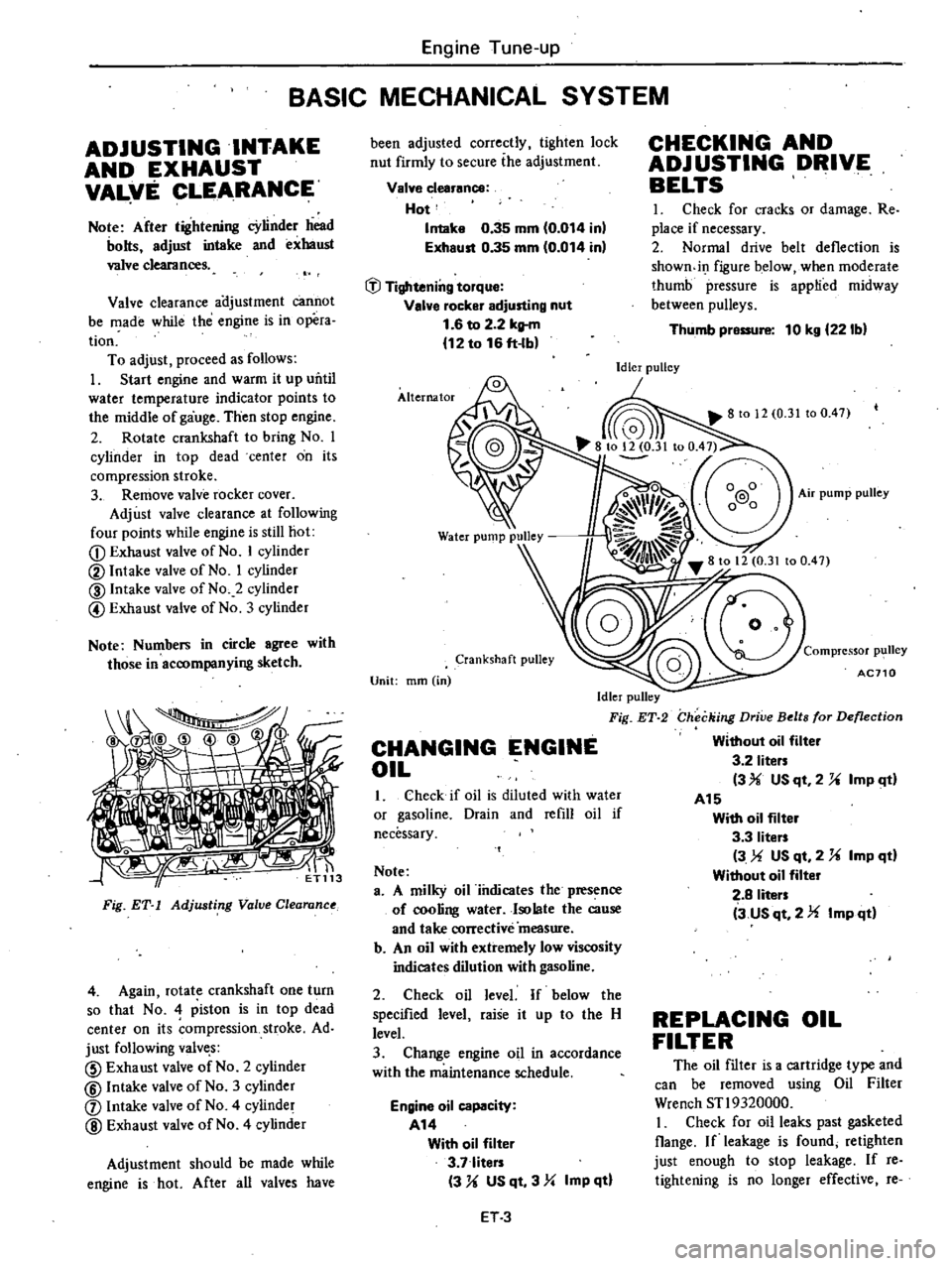
ADJUSTING
INTAKE
AND
EXHAUST
VAL
fE
CLEARANCE
Note
After
tightening
cYlinder
head
bolts
adjust
intake
and
exhaust
valve
clearances
Valve
clearance
ai
ljustment
cannot
be
made
while
the
engine
is
in
opera
tion
To
adjust
proceed
as
follows
I
Start
engine
and
warm
it
up
uritil
water
temperature
indicator
points
to
the
middle
of
gauge
Then
stop
engine
2
Rotate
crankshaft
to
bring
No
I
cylinder
in
top
dead
center
on
its
compression
stroke
3
Remove
valve
rocker
cover
Adjust
valve
clearance
at
following
four
points
while
engine
is
still
hot
CD
Exhaust
valve
of
No
I
cylinder
@
Intake
valve
of
No
I
cylinder
@
Intake
valve
of
No
2
cylinder
@
Exhaust
valve
of
No
3
cylinder
Note
Numbers
in
circle
agree
with
those
in
accompanying
sketch
tiri
Fig
ET
1
Adjusting
Value
Clearanu
4
Again
rotate
crankshaft
one
turn
so
that
No
4
piston
is
in
top
dead
center
on
its
ompression
stroke
Ad
just
following
valve
s
CID
Exhaust
valve
of
No
2
cylinder
@
Intake
valve
of
No
3
cylinder
j
Intake
valve
of
No
4
cylinder
@
Exhaust
valve
of
No
4
cylinder
Adjustment
should
be
made
while
engine
is
hot
After
all
valves
have
been
adjusted
correctly
tighten
lock
nut
firmly
to
secure
ihe
adjustment
Valve
clearance
Hot
Intake
0
35
mm
0
014
inl
Exhaust
0
35
mm
0
014
in
tJl
Tightening
torque
Valve
rocker
adjusting
nut
1
6
to
2
2
kltm
12
to
16
ft
lb
Alternator
Crankshaft
pulley
Unit
mm
in
Idler
pulley
Fig
ET
2
CHANGING
ENGINE
OIL
1
Check
if
oil
is
diluted
with
water
or
gasoline
Drain
and
refill
oil
if
necessary
Note
a
A
milky
oil
iiulicates
the
presence
of
cooling
water
Isolate
the
cause
and
take
corrective
measure
b
An
oil
with
extremely
low
viscosity
indicates
dilution
with
gasoline
2
Check
oil
level
If
below
the
specified
level
raise
it
up
to
the
H
level
3
Change
engine
oil
in
accordance
with
the
maintenance
schedule
Engine
oil
capacity
A14
With
oil
filter
3
7
liters
3
U
US
qt
3
Yo
Imp
qtl
ET3
CHECKING
AND
ADJUSTING
DRIVE
BELTS
I
Check
for
cracks
or
damage
Re
place
if
necessary
2
Normal
drive
belt
deflection
is
showndI
figure
below
when
moderate
thumb
pressure
is
applied
midway
between
pulleys
Thumb
pressure
10
kg
221bl
Idler
pulley
Compressor
p1
111ey
AC710
Checking
Drive
Belts
for
Deflection
Without
oil
filter
3
2
liters
3
USqt
2
U
ImP
ltl
A15
With
oil
filter
3
3
liters
3
US
qt
2
U
Imp
qd
Without
oil
filter
2
8
liters
3
us
qt
2
Imp
qd
REPLACING
OIL
FILTER
The
oil
filter
is
a
cartridge
type
and
can
be
removed
using
Oil
Filter
Wrench
STl9320000
I
Check
for
oil
leaks
past
gasketed
Oange
If
leakage
is
found
retighten
just
enough
to
stop
leakage
If
reo
tightening
is
no
longer
effective
re
Page 20 of 548
SO
B
T
D
C
l650
rpm
Non
California
models
except
Canada
100
B
T
D
C
650
rpm
Canada
models
Note
On
FU
models
ignition
timing
is
set
under
a
condition
where
distributor
vacuum
hose
is
discon
nected
If
necessary
adjust
ignition
timing
as
follows
I
Loosen
set
screw
until
dis
tributor
c
uJ
be
moved
by
hand
2
Adjust
ignition
timing
to
speci
fications
3
Lock
distributor
set
screw
and
make
sure
that
timing
is
correct
YJ
Fig
T
9
Adjusting
Ignition
Timing
7
On
FU
models
proceed
as
fol
lows
I
Remove
blind
plug
from
dis
tributor
vacuum
hose
and
connect
hose
to
distributor
diaphragm
2
If
engine
speed
varies
in
this
state
set
idling
speed
at
specified
value
with
throttle
adjusting
screw
CHECKING
IGNITION
WIRING
Use
an
ohmmeter
to
check
resist
ance
on
high
tension
cables
1
Disconnect
cables
from
spark
plugs
and
remove
distributor
together
with
high
tension
cables
Note
Do
not
remove
cables
from
cap
Engine
Tune
up
2
Connect
the
ohmmeter
between
cable
terminal
on
the
spark
plug
side
and
the
corresponding
electrode
inside
cap
3
If
the
resistance
is
more
than
30
000
ohms
remove
cable
from
cap
and
check
the
cable
resistance
only
If
resistance
is
still
more
than
30
000
ohms
replace
c3ble
assembly
Fig
ET
IO
Checking
High
Tension
Cable
u
s
A
models
Type
FU
models
Standard
Hot
type
Cold
type
U
S
A
models
Canada
models
r
1g
mm
in
FU
models
Canada
models
Tightening
torque
kg
m
ft
lb
ET
6
Stan
rd
Hot
type
Cold
type
S
aridard
Hot
type
Cold
type
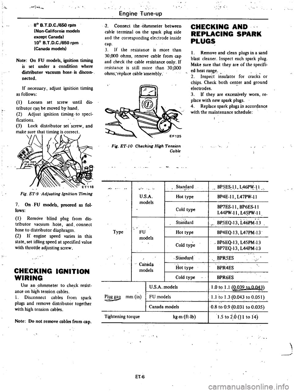
CHECKING
AND
REPLACING
SPARK
PLUGS
I
Remove
and
clean
plugs
in
a
sand
blast
cleaner
Inspect
each
spark
plug
Make
sure
that
they
are
of
the
specifi
ed
heat
range
2
Inspect
insulator
for
cracks
or
chips
Check
both
center
and
ground
electrodes
3
If
they
are
excessively
worn
re
place
with
new
spark
plugs
4
Replace
spark
plugs
in
accordance
with
the
maintenance
schedule
BP
ES
ll
L46PW
l
BP4E
ll
L47PW
ll
BP7ES
ll
BP6ES
ll
L44PW
II
L4
PW
11
BP5
EQ
13
L46PM
13
BP4EQ
13
L47PM
13
BP6EQ
13
L45PM
13
BP7EQ
13
L44PM
13
BPR5ES
BPR4ES
BPR6ES
1
0
to
1
1
LQ39
to
0
043
l
l
to
1
3
0
043
to
0
051
0
8
to
0
9
0
031
to
0
035
1
5
to
i
6
P
to
14
Page 29 of 548
IBnition
and
fuel
system
Ignition
timing
Manual
transmission
models
Automatic
transmission
models
in
D
position
1
Spark
plug
Gap
U
s
A
models
Canada
models
FU
models
High
tension
cable
resistance
CO
percentage
at
idling
speed
No
air
Manual
transmission
models
Automatic
transmission
models
f
in
D
position
Evaporatlv
emission
control
system
Supplied
pressure
l
Pressure
variation
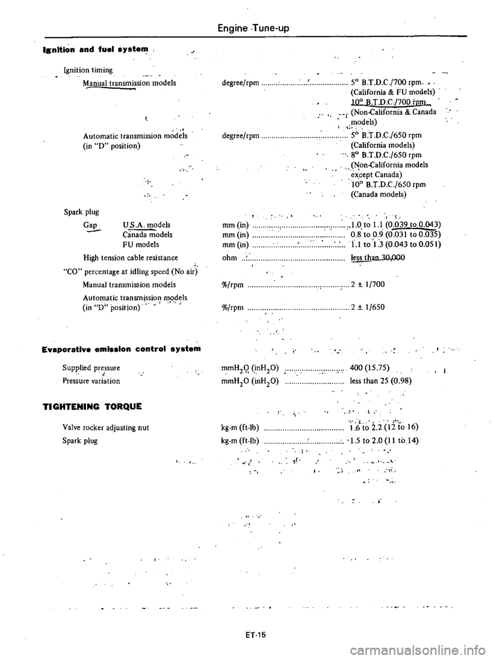
TIGHTENING
TORQUE
Valve
rocker
adjusting
nut
Spark
plug
Engine
Tune
up
degree
rpm
degree
rpm
mm
in
mm
in
mm
in
ohm
rpm
rpm
mmH29
inH20
mmH20
inHP
kg
m
ft
lb
kg
m
ft
lb
ET1S
SO
B
T
D
C
j700
rpm
California
FU
models
T
D
CJ700
i
m
r
Non
California
Canada
models
SO
B
T
D
C
j6S0
rpm
California
models
80
B
T
D
C
j6S0
rpm
Non
California
models
ex
cept
Canada
100
B
T
D
C
j6S0
rpm
Canada
models
1
0
to
l
l
0
039
to
0
043
0
8
to
0
9
0
031
to
0
035
LI
to
1
3
0
043
to
O
OSI
an
3O
OOO
2
r
1
700
2
r
1
6S0
400
IS
7S
less
than
2S
0
98
I
f
r
1
6
to
2
2
12
to
16
1
5
to
2
0
11
to
14
jf
0
Page 31 of 548
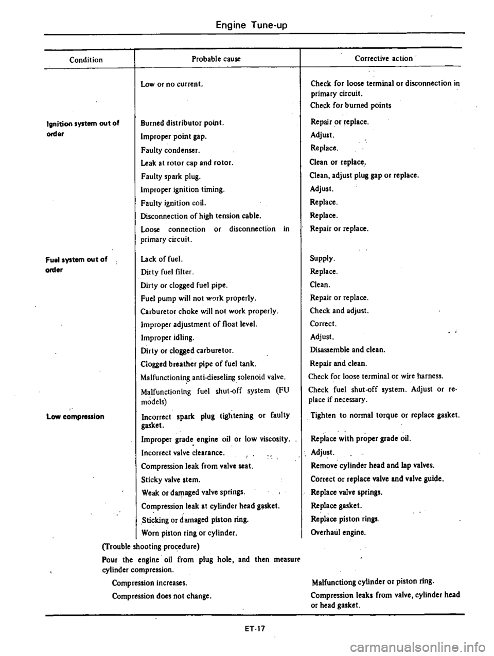
Engine
Tune
up
Condition
Probable
cause
Low
or
no
current
Ignition
system
out
of
order
Burned
distributor
point
Improper
point
gap
Faulty
condenser
Leak
at
rotor
cap
and
rotor
Faulty
spark
plug
Improper
ignition
timing
Faulty
ignition
coil
Disconnecrion
of
high
tension
cable
Loose
connection
or
disconnection
in
primary
circuit
Lack
offuel
Dirty
fuel
filter
Dirty
or
clogged
fuel
pipe
Fuel
pump
will
not
w0rk
properly
Carburetor
choke
will
not
work
properly
Improper
adjustment
of
float
level
Improper
idling
Dirty
or
clogged
carburetor
Clogged
breather
pipe
of
fuel
tank
Malfunctionin
g
anti
dieseling
solenoid
valve
Malfunctioning
fuel
shut
off
system
FU
models
Incorrect
spark
plug
tightening
or
faulty
gasket
Improper
grade
engine
oil
or
low
viscosity
Incorrect
valve
clearance
Compression
leak
from
valve
seat
Sticky
valve
stem
Weak
or
damaged
valve
springs
Compression
leak
at
cylinder
head
gasket
Sticking
or
damaged
piston
ring
Worn
piston
ring
or
cylinder
Trouble
looting
procedure
Pour
the
engine
oil
from
plug
hole
and
then
measurt
cylinder
compression
Fuel
system
out
of
order
Low
compression
Compression
increases
Compression
does
not
change
ET
17
Corrective
action
Check
for
loose
terminal
or
disconnection
in
primary
circuit
Check
for
burned
points
Repair
or
replace
Adjust
Replace
Clean
or
replace
Clean
adjust
plug
gap
or
replace
Adjust
Replace
Replace
Repair
or
replace
Supply
Replace
Clean
Repair
or
replace
Check
and
adjust
Correct
Adjust
Disassemble
and
clean
Repair
and
clean
Check
for
loose
terminal
or
wire
harness
Check
fuel
shut
off
system
Adjust
or
re
place
if
necessary
Tighten
to
normal
torque
or
replace
gasket
Replace
with
proper
grade
oil
Adjust
Remove
cylinder
head
and
lap
valves
Correct
or
replace
valve
and
valve
guide
Replace
valve
springs
Replace
gasket
Replace
piston
rings
Overhaul
engine
Malfunctiong
cylinder
or
piston
ring
Compression
leaks
from
valve
cylinder
head
or
head
gasket
Page 35 of 548
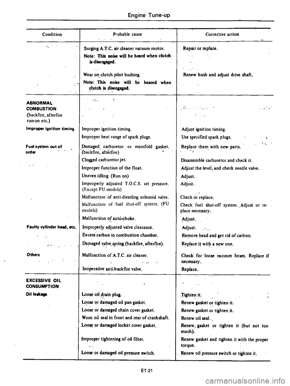
Condition
ABNORMAL
COMBUSTION
backfire
afterfire
run
on
etc
Improper
ignition
timing
Fuel
system
out
of
order
Feulty
cylinder
heed
etc
Others
EXCESSIVE
OIL
CONSUMPTION
Oilleek8111
Engine
Tune
up
Probable
cause
Surging
A
T
C
air
cleaner
vacuum
motor
Note
This
noise
will
be
hmnl
when
clutch
iI
disengaged
We
r
on
clutch
pilot
bushing
Not
e
This
noise
will
be
heared
when
utch
iI
disengaged
Improper
ignition
timing
Improper
heal
range
of
spark
plugs
Damaged
carburetor
or
manifold
gasket
backfire
aftedire
Clogged
carburetor
jet
Improper
function
of
the
float
Uneven
idling
Run
on
Improperly
adjusted
T
O
C
S
set
pressure
Except
FU
models
Malfunction
of
anti
dieseling
solenoid
valve
Malfunction
of
fuel
shut
off
system
FU
models
Malfunction
or
auto
hoke
Improper
y
adjusted
valve
clearance
Excess
carbon
in
combustion
chamber
Da
laged
alve
spring
backfire
after
he
Malfunction
of
A
T
C
air
cleaner
Inoperative
anti4lackfire
valve
Loose
oil
tain
plUI
ose
or
damaged
oil
pan
gasket
Loose
or
damaled
chain
cover
gasket
Wom
oil
seal
in
front
and
rear
of
crankshaft
Loo
or
damaged
locker
cover
gasket
Improper
lilhtening
of
oU
filter
Loose
or
damaled
oil
pressure
switch
ET
21
Corrective
action
Repair
or
replace
Renew
bush
and
adjust
drive
shaft
Adjust
ignition
liming
Use
specified
spark
plugs
Replace
them
with
new
parts
Disassemble
carburetor
and
check
it
Adjust
the
level
and
check
needle
valve
Adjust
Adjust
Check
or
replace
Check
fuel
shut
off
system
Adjust
or
re
place
necessary
Adjust
Adjust
Remove
head
and
get
rid
of
carbon
Replace
it
wit
a
new
one
Check
for
loose
vacuum
hoses
Replace
if
necessary
Replace
Tighten
it
Renew
lasket
or
tighten
iI
Renew
gasket
or
lighten
it
Renew
oil
seal
Renew
gasket
r
lighten
it
but
not
too
much
Renew
gasket
and
tighten
it
with
the
proper
torque
Renew
oil
pressure
switch
or
tighten
it
Page 38 of 548
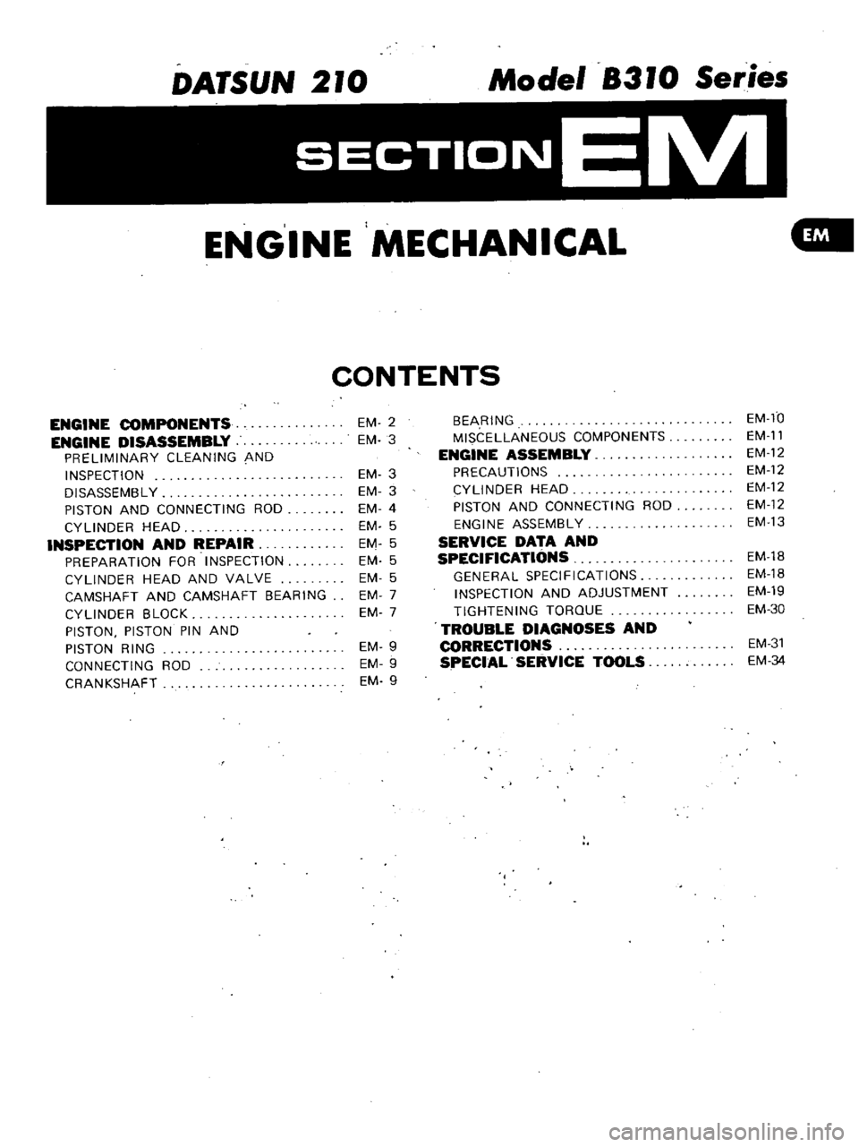
DATSUN
210
Model
8310
Series
ENGINE
MECHANICAL
GIll
CONTENTS
ENGINE
COMPONENTS
ENGINE
DISASSEMBLY
PRELIMINARY
CLEANING
AND
INSPECTION
DISASSEMBL
Y
PISTON
AND
CONNECTING
ROD
CYLINDER
HEAD
INSPECTION
AND
REPAIR
PREPARATION
FOR
INSPECTION
CYLINDER
HEAD
AND
VALVE
CAMSHAFT
AND
CAMSHAFT
BEARING
CYLINDER
BLOCK
PISTON
PISTON
PIN
AND
PISTON
RING
CONNECTING
ROD
CRANKSHAFT
EM
2
EM
3
EM
3
EM
3
EM
4
EM
5
EM
5
EM
5
EM
5
EM
7
EM
7
EM
9
EM
9
EM
9
BEARING
MISCELLANEOUS
COMPONENTS
ENGINE
ASSEMBLY
PRECAUTIONS
CYLINDER
HEAD
PISTON
AND
CONNECTING
ROD
ENGINE
ASSEMBLY
SERVICE
DATA
AND
SPECIFICATIONS
GENERAL
SPECIFICATIONS
INSPECTION
AND
ADJUSTMENT
TIGHTENING
TORQUE
TROUBLE
DIAGNOSES
AND
CORRECTIONS
SPECIAL
SERVICE
TOOLS
EM
fO
EM
ll
EM
12
EM
12
EM
12
EM
12
EM
13
EM
lB
EM
lB
EM
19
EM
30
EM
31
EM
34
Page 47 of 548
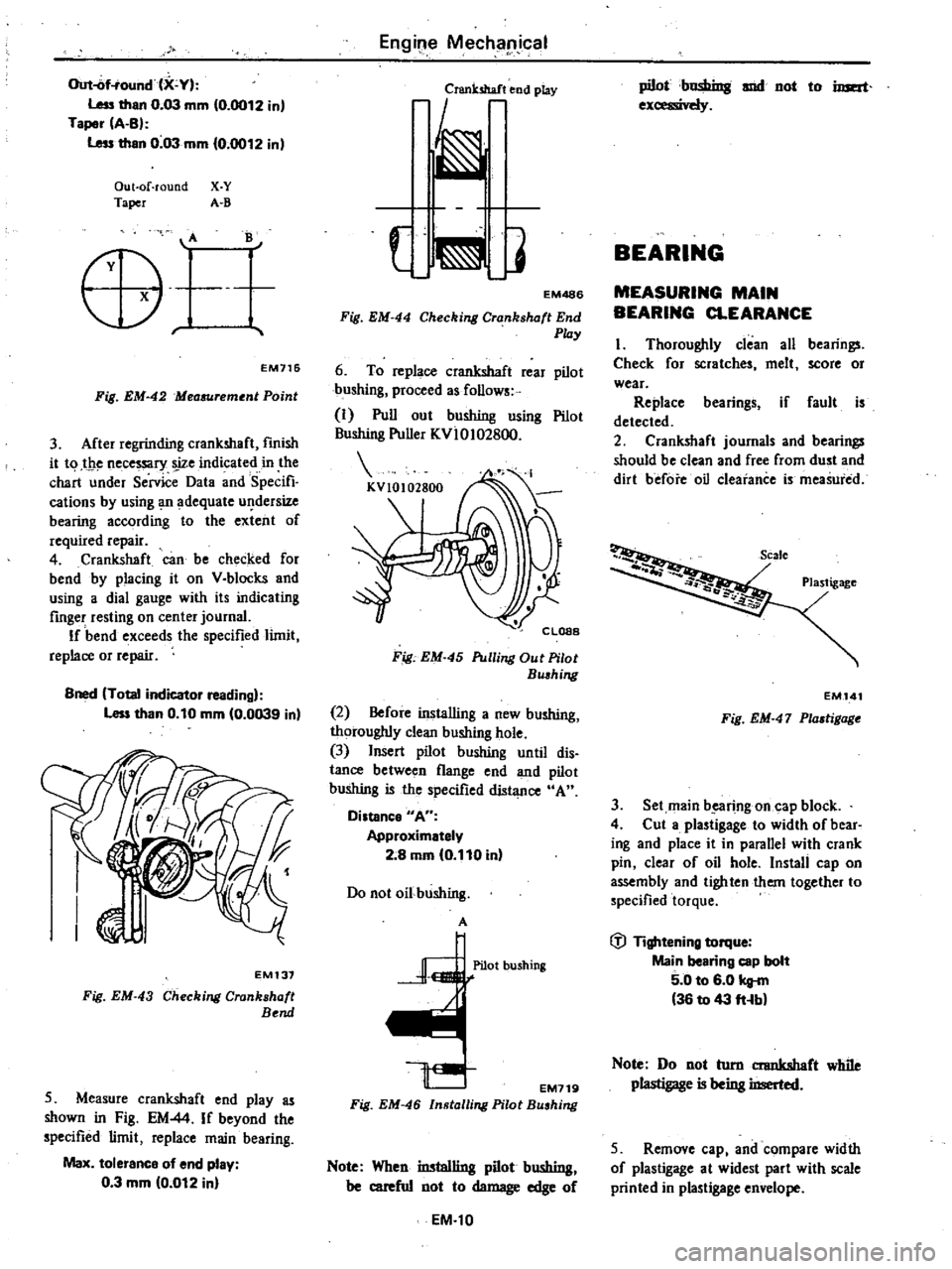
Out
of
ound
X
Y
Less
than
0
03
mm
10
0012
in
Taper
A
B
Less
than
0
03
mm
0
0012
in
Out
of
round
X
Y
Taper
A
B
B
o
r
EM716
Fig
EM
42
Mea6Urement
Point
3
After
regrinding
crankshaft
fmish
it
t
1
t
1e
necessary
s
ize
indicated
in
the
chart
under
Service
Data
and
Specifi
cations
by
using
Ill
adequate
u
dersize
bearing
according
to
the
extent
of
required
repair
4
Crankshaft
can
be
checked
for
bend
by
placing
it
on
V
blocks
and
using
a
dial
gauge
with
its
indicating
finger
resting
on
center
journal
If
bend
exceeds
the
specified
limit
replace
or
repair
Bned
Total
indicator
reading
Less
than
0
10
mm
0
0039
in
EM137
Fig
EM
43
Checking
Crankshaft
Bend
5
Measure
crankshaft
end
play
as
shown
in
Fig
EM
44
If
beyond
the
specified
limit
replace
main
bearing
Max
tolerance
of
end
play
0
3
mm
10
012
in
Engil
e
Mechllpjcal
Crsnk5haf
end
play
EM486
Fig
EM
44
Checking
Crankshaft
End
Play
6
To
replace
crankshaft
rear
pilot
bushing
proceed
as
follows
1
Pull
out
bushing
using
Pilot
Bushing
Puller
KvloI02800
Fig
EM
45
Pulling
Out
Pilot
Bushing
2
Before
installing
a
new
bushing
thoroughly
clean
bushing
hole
3
Insert
pilot
bushing
until
dis
tance
between
flange
end
and
pilot
bushing
is
the
specified
diJ1l
nce
A
Distance
A
Approximetely
2
8
mm
0
110
in
Do
not
oil
bushing
A
Pilot
bushing
EM719
Fig
EM
46
Installing
Pilot
Bushing
Note
When
installing
pilot
bushing
be
careful
not
to
damage
edge
of
EM
l0
pilot
C
snd
not
to
imat
1
1
1
BEARING
MEASURING
MAIN
BEARING
CLEARANCE
I
Thoroughly
clean
all
bearings
Check
for
scratches
melt
score
or
wear
Replace
bearings
if
fault
is
detected
2
Crankshaft
journals
and
bearings
should
be
clean
and
free
from
dust
and
dirt
before
oil
Clearance
is
meaSured
Plastigage
EM
141
Fig
EM
47
Plastigage
3
Set
main
b
e1lfing
on
cap
block
4
Cut
a
plastigage
to
width
of
bear
ing
and
place
it
in
parallel
with
crank
pin
clear
of
oil
hole
Install
cap
on
assembly
and
tighten
them
together
to
specified
torque
fj
Tightening
torque
Main
bearing
cop
bolt
5
0
to
6
0
kg
m
36
to
43
fHb
Note
Do
not
turn
crankshaft
while
plastigage
is
being
inserted
5
Remove
cap
and
compare
width
of
plastigage
at
widest
part
with
scale
printed
in
plastigage
envelope
Page 48 of 548
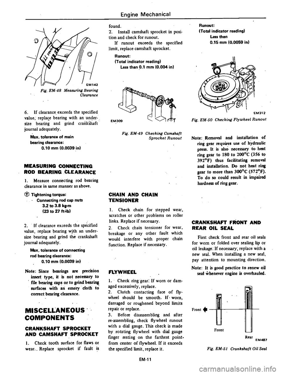
EM142
Fig
EM
48
Measuring
Bearing
Clearance
6
If
clearance
exceeds
the
specified
value
replase
bearing
with
an
under
size
bearing
and
grind
crankshaft
journal
adequately
Max
tolerance
of
main
bearing
clearance
0
10
mm
0
0039
in
MEASURING
CONNECTING
ROD
BEARING
CLEARANCE
I
Measure
connecting
rod
bearing
clearance
in
same
manner
as
above
tfl
Tightening
torque
Connecting
rod
cap
nuts
3
2
to
3
8
kg
m
23
to
27
fHb
2
If
clearance
exceeds
the
specified
value
replace
bearing
with
an
under
size
bearing
and
grind
the
crankshaft
journal
adequately
Max
tolerance
of
connecting
rod
bearing
clearance
0
10
mm
0
0039
in
Note
Since
bearings
are
precision
insert
type
it
is
not
necessary
to
file
bearing
caps
or
to
grindbeari
surfaces
with
an
emery
cloth
to
correct
bearing
clearance
MISCELLANEOUS
COMPONENTS
CRANKSHAFT
SPROCKET
AND
CAMSHAFT
SPROCKET
I
Check
tooth
surface
for
flaws
or
wear
Replace
sprocket
if
fault
is
Engine
Mechanical
found
2
Install
camshaft
sprocket
in
posi
tion
and
check
for
runout
If
runout
exceeds
the
specified
limit
replace
camshaft
sprocket
Runout
Total
indicator
reading
Less
than
0
1
mm
0
004
in
EM309
Fig
EM
49
Checking
Cam
haft
Sprocket
Runout
CHAIN
AND
CHAIN
TENSIONER
I
Check
chain
for
stepped
wear
scratches
or
other
problems
on
roller
links
Replace
if
necessary
2
Check
chain
tensioner
for
wear
breakage
or
any
other
fault
which
would
interfere
with
proper
chain
function
Replace
if
necessary
FLYWHEEL
I
Check
ring
gear
If
worn
or
dam
aged
excessively
replace
2
Clutch
contacting
face
of
fly
wheel
should
be
smooth
If
worn
damaged
or
roughened
beyond
limits
repair
or
replace
3
Before
disassembling
and
after
re
assembling
check
flywheel
run
out
with
a
dial
gauge
This
check
is
made
by
rotating
flywheel
with
dial
gauge
finger
resting
on
the
farthest
point
from
center
of
flywheel
If
it
exceeds
the
specified
limit
replace
it
EM
II
Runout
Total
indicator
reading
Less
then
0
15
mm
0
0059
in
Fig
EM
50
Checking
Flywheel
Runout
Note
Removal
and
installation
of
ring
gear
requires
use
of
hydraulic
press
It
is
also
necessary
to
heat
ring
gear
to
180
to
2000C
356
to
3920F
thus
facilitating
removal
and
installation
Do
not
heat
ring
gear
to
more
than
3000C
5nOF
To
do
so
could
result
in
impaired
hardness
of
ring
gear
CRANKSHAFT
FRONT
AND
REAR
OIL
SEAL
First
check
front
and
rear
oil
seals
for
worn
or
folded
over
sealing
lip
or
oil
leakage
If
necessary
replace
with
a
new
seal
When
installing
a
new
seal
pay
attention
to
mounting
direction
Note
It
is
good
practice
to
renew
oil
seal
whenever
engine
is
overhauled
Front
u
Front
Rear
EM487
Fig
EM
51
Cranhhaft
Oil
Seal
Page 50 of 548
2
Install
piston
rings
Install
so
that
stamped
mark
on
ring
faces
upward
Note
a
There
are
two
types
of
top
rings
One
is
conventional
special
cast
iron
ring
the
other
is
steel
ring
which
is
called
a
high
power
ring
b
Second
ring
has
larger
taper
surface
than
top
ring
c
In
combined
oil
ring
upper
rail
is
same
as
lower
one
I
lnT
10
EM158
Fig
EM
57
Installing
Piston
Ring
3
Fix
bearings
on
connecting
rod
and
connecting
rod
cap
VALVE
ROCKER
SHAFT
ASSEMBLY
Install
parts
as
shown
in
Fig
EM
58
in
place
on
rocker
shaft
@
EM491
Fig
EM
58
Valve
Rocker
Shaft
As
embly
ENGINE
ASSEMBLY
I
The
first
step
in
engine
assembly
is
to
bolt
Engine
Attachment
KV
10
102500
to
right
hand
side
of
cylinder
block
In
succession
install
block
in
Engine
Stand
ST0501S000
with
engine
bottom
up
2
Apply
a
light
coat
of
engine
oil
to
Engine
Mechanical
sliding
surfaces
of
valve
lifters
insert
lifters
in
holes
in
cylinder
block
3
To
install
camshaft
be
sure
to
coat
sliding
surfaces
of
camshaft
bush
ings
with
a
light
coat
of
engine
oil
Insert
camshaft
in
cylinder
block
from
front
side
of
engine
exercising
care
not
to
damage
camshaft
bushings
4
Install
camshaft
locating
plate
and
tighten
bolts
to
specified
torque
i
l
Tightening
torque
Camshaft
locating
plate
0
4
to
0
5
kg
m
2
9
to
3
6
ft
Ibl
Note
Set
locating
plate
so
as
the
Lower
mark
comes
to
engine
bottom
side
Fig
EM
59
Installing
Camshaft
Locating
Plate
5
Install
baffle
plate
and
steel
net
6
Set
main
bearings
at
proper
por
tion
of
cylinder
block
and
caps
No
1
2
3
0
0
0
0
0
0
I
I
J
upperW
r
Lower
J
EM492
Fig
EM
60
Main
Bearings
and
Caps
Note
a
Center
bearing
No
3
is
a
flanged
type
for
thrust
force
b
Two
internal
bearings
No
2
and
No
4
are
of
the
same
type
c
Front
bearing
No
I
is
the
same
type
as
rear
bearing
No
5
EM
13
d
All
bearings
except
No
2
and
No
4
are
not
interchangeable
between
upper
and
lower
bearings
7
Apply
engine
oil
to
main
bearing
surfaces
on
both
sides
of
cylinder
block
and
cap
Install
crankshaft
8
Install
main
bearing
cap
and
tight
en
bolts
to
specified
torque
lil
Tightening
torque
Main
bearing
cap
5
0
to
6
0
kg
m
36
to
43
ft
lb
Note
a
Apply
seal
to
each
rear
main
bear
ing
contact
comer
of
cylinder
block
as
shown
in
F
EM
61
EM493
Fig
EM
6
Applying
Sealant
b
Arrange
parts
so
arrow
mark
on
bearing
cap
faces
toward
front
of
engine
c
Prior
to
tightening
bearing
cap
bolts
place
bearing
cap
in
proper
position
by
shifting
crankshaft
in
axial
direction
d
Tighten
bearing
cap
bolts
gradually
in
two
to
three
stages
outwardly
from
center
bearing
in
the
sequence
shown
in
Fig
EM
62
e
After
securing
bearing
cap
bolts
ascertain
that
crankshaft
turns
smoothly
@I
EM494
Fig
EM
62
Torque
Sequence
of
Cap
Bolts