service interval DATSUN 210 1979 Service Manual
[x] Cancel search | Manufacturer: DATSUN, Model Year: 1979, Model line: 210, Model: DATSUN 210 1979Pages: 548, PDF Size: 28.66 MB
Page 403 of 548

Engine
Control
Fuel
Exhaust
Systems
REMOVAL
WARNING
When
replacing
fuel
line
parts
be
sure
to
observe
the
following
a
Put
a
CAUTION
INFLAM
MABLE
sign
in
workshop
b
Be
sure
to
furnish
workshop
with
In
asphyxiator
c
Be
sure
to
disconnect
battery
ground
cable
before
conducting
operations
d
Put
drained
fuel
in
an
explosion
proof
container
and
put
on
lid
securely
FUEL
TANK
Sedan
I
Disconnect
battery
ground
cable
2
Drain
fuel
from
fuel
tank
then
disconnect
fuel
hose
3
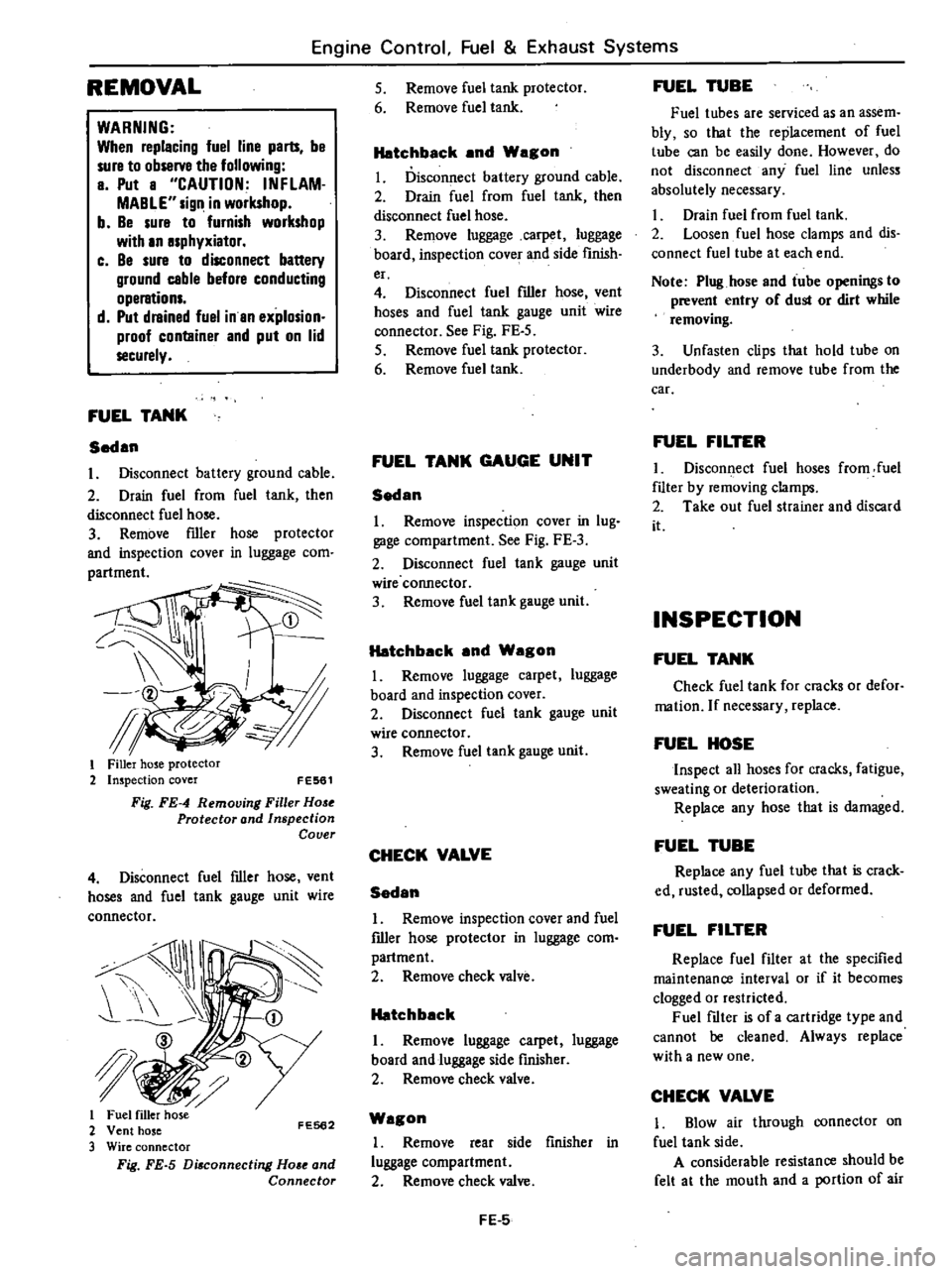
Remove
filler
hose
protector
and
inspection
cover
in
luggage
com
i
tl
f
I
Filler
hose
protector
2
Inspection
cover
FE561
Fig
FE
4
Removing
Filler
Hose
Protector
and
Inspection
Cover
4
Disconnect
fuel
filler
hose
vent
hoses
and
fuel
tank
gauge
unit
wire
connector
I
JI
I
2
FE562
3
Fig
FE
5
Di
connecting
Ho
e
and
Connector
5
Remove
fuel
tank
protector
6
Remove
fuel
tank
Hatchback
and
Wagon
I
Disconnect
battery
ground
cable
2
Drain
fuel
from
fuel
tank
then
disconnect
fuel
hose
3
Remove
luggage
carpet
luggage
board
inspection
covef
and
side
finish
er
4
Disconnect
fuel
filler
hose
vent
hoses
and
fuel
tank
gauge
unit
wire
connector
See
Fig
FE
5
5
Remove
fuel
tank
protector
6
Remove
fuel
tank
FUEL
TANK
GAUGE
UNIT
Sedan
1
Remove
inspection
cover
in
lug
gage
compartment
See
Fig
FE
3
2
Disconnect
fuel
tank
gauge
unit
wire
connector
3
Remove
fuel
tank
gauge
unit
Hatchback
and
Wagon
I
Remove
luggage
carpet
luggage
board
and
inspection
cover
2
Disconnect
fuel
tank
gauge
unit
wire
connector
3
Remove
fuel
tank
gauge
unit
CHECK
VALVE
Sedan
I
Remove
inspection
cover
and
fuel
filler
hose
protector
in
luggage
com
partment
2
Remove
check
valve
Hatchback
I
Remove
luggage
carpet
luggage
board
and
luggage
side
finisher
2
Remove
check
valve
Wagon
I
Remove
rear
side
finisher
in
luggage
compartment
2
Remove
check
valve
FE
5
FUEL
TUBE
Fuel
tubes
are
serviced
as
an
assem
bly
so
that
the
replacement
of
fuel
tube
can
be
easily
done
However
do
not
disconnect
any
fuel
line
unless
absolutely
necessary
Drain
fuel
from
fuel
tank
2
Loosen
fuel
hose
clamps
and
dis
connect
fuel
tube
at
each
end
Note
Plug
hose
and
tube
openings
to
prevent
entry
of
dust
or
dirt
while
removing
3
Unfasten
clips
that
hold
tube
on
underbody
and
remove
tube
from
the
car
FUEL
FILTER
I
Disconnect
fuel
hoses
from
fuel
filter
by
removing
clamps
2
Take
out
fuel
strainer
and
discard
it
INSPECTION
FUEL
TANK
Check
fuel
tank
for
cracks
or
defor
mation
If
necessary
replace
FUEL
HOSE
Inspect
all
hoses
for
cracks
fatigue
sweating
or
deterioration
Replace
any
hose
that
is
damaged
FUEL
TUBE
Replace
any
fuel
tube
that
is
crack
ed
rusted
collapsed
or
deformed
FUEL
FILTER
Replace
fuel
filter
at
the
specified
maintenance
interval
or
if
it
becomes
clogged
or
restricted
Fuel
filter
is
of
a
cartridge
type
and
cannot
be
cleaned
Always
replace
with
a
new
one
CHECK
VALVE
1
Blow
air
through
connector
on
fuel
tank
side
A
considerable
resistance
should
be
felt
at
the
mouth
and
a
portion
of
air
Page 517 of 548

I
I
3
Set
temperature
lever
to
max
imum
cold
position
Air
Conditioning
4
Sefblower
to
maximum
speed
S
Check
sight
glass
after
the
lapse
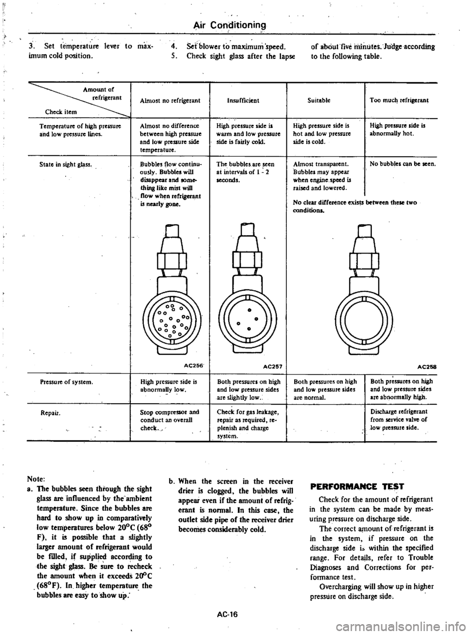
Almost
no
refrigerant
Check
item
Temperature
of
high
prenure
and
low
pressure
lines
Almost
no
difference
between
high
presswc
and
lowpressufC
side
temperature
State
in
sight
gl
ltS3
Bubbles
flow
continu
ously
Bubbles
will
disappear
and
some
thing
like
mist
wiD
flow
when
rerrigel
l
llt
is
nearly
gone
AC256
Pressure
of
system
High
pressure
side
is
abnormally
low
Repair
Stop
compressor
and
conduct
an
overall
check
Note
a
The
bubbles
seen
tbrough
the
sight
glass
are
influenced
by
the
ambient
tempemture
Since
the
bubbles
are
bard
to
show
up
in
comparatively
low
tempemtures
below
200C
680
F
it
is
possible
that
a
slightly
larger
amouot
of
refrigemot
would
be
filled
if
supplied
according
to
tbe
sight
glass
Be
sure
to
recheck
the
amount
when
it
exceedS
20
C
680F
In
higher
tempemture
tbe
bubbles
are
easy
to
show
up
Insufficient
High
pressure
side
is
warm
and
low
pressure
side
is
fairly
cokt
The
bubbles
are
seen
at
intervals
of
1
2
seconds
AC257
Both
pressures
on
high
and
low
pressure
sides
are
slightly
low
Check
for
gas
leakage
repair
as
required
re
plenish
and
chaxge
system
b
Wben
the
screen
in
tbe
receiver
drier
is
clogged
tbe
bubbles
wiD
appear
even
if
the
amount
of
refrig
erant
is
nonnaL
In
this
case
tbe
outlet
side
pipe
of
tbe
receiver
drier
becomes
considembly
cold
AC
16
of
abOut
five
rilintJtes
Jullgeaccording
to
the
following
table
Suitable
Too
much
refrigerant
High
pressure
side
is
hot
and
low
pressure
side
is
cold
High
pressure
side
is
abnormally
hot
Almost
transparent
Bubbles
may
appear
when
engine
speed
is
raised
and
lowered
No
bubbles
can
be
seen
No
clear
difference
exists
these
two
conditions
nl
AC258
Both
pre55ures
on
high
and
low
pressure
sides
are
normal
Both
pressures
on
high
and
low
pressure
sides
are
abnonnally
high
Discharge
refrigerant
from
service
valve
of
low
pressure
side
PERFORMANCE
TEST
Check
for
the
amount
of
refrigerant
in
the
system
can
be
made
by
meas
uring
pressure
on
discharge
side
The
correct
amount
of
refrigerant
is
in
the
system
if
pressure
on
the
discharge
side
i
within
the
specified
range
For
details
refer
to
Trouble
Diagnoses
and
Corrections
for
per
fannance
test
Overcharging
will
show
up
in
higher
presstJre
on
discharge
side