stop start DATSUN 210 1979 Service Manual
[x] Cancel search | Manufacturer: DATSUN, Model Year: 1979, Model line: 210, Model: DATSUN 210 1979Pages: 548, PDF Size: 28.66 MB
Page 17 of 548
Engine
Tune
up
BASIC
MECHANICAL
SYSTEM
ADJUSTING
INTAKE
AND
EXHAUST
VAL
fE
CLEARANCE
Note
After
tightening
cYlinder
head
bolts
adjust
intake
and
exhaust
valve
clearances
Valve
clearance
ai
ljustment
cannot
be
made
while
the
engine
is
in
opera
tion
To
adjust
proceed
as
follows
I
Start
engine
and
warm
it
up
uritil
water
temperature
indicator
points
to
the
middle
of
gauge
Then
stop
engine
2
Rotate
crankshaft
to
bring
No
I
cylinder
in
top
dead
center
on
its
compression
stroke
3
Remove
valve
rocker
cover
Adjust
valve
clearance
at
following
four
points
while
engine
is
still
hot
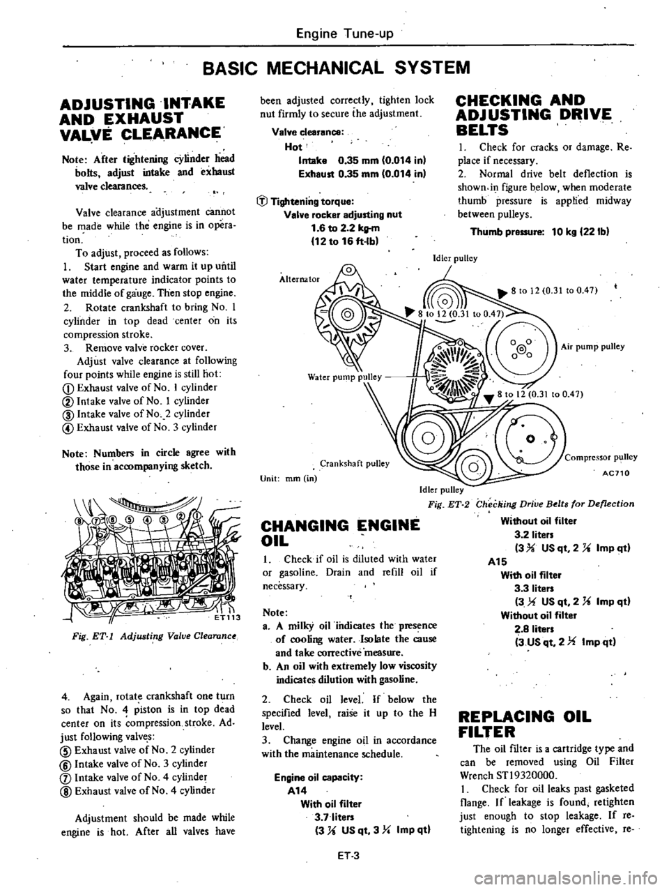
CD
Exhaust
valve
of
No
I
cylinder
@
Intake
valve
of
No
I
cylinder
@
Intake
valve
of
No
2
cylinder
@
Exhaust
valve
of
No
3
cylinder
Note
Numbers
in
circle
agree
with
those
in
accompanying
sketch
tiri
Fig
ET
1
Adjusting
Value
Clearanu
4
Again
rotate
crankshaft
one
turn
so
that
No
4
piston
is
in
top
dead
center
on
its
ompression
stroke
Ad
just
following
valve
s
CID
Exhaust
valve
of
No
2
cylinder
@
Intake
valve
of
No
3
cylinder
j
Intake
valve
of
No
4
cylinder
@
Exhaust
valve
of
No
4
cylinder
Adjustment
should
be
made
while
engine
is
hot
After
all
valves
have
been
adjusted
correctly
tighten
lock
nut
firmly
to
secure
ihe
adjustment
Valve
clearance
Hot
Intake
0
35
mm
0
014
inl
Exhaust
0
35
mm
0
014
in
tJl
Tightening
torque
Valve
rocker
adjusting
nut
1
6
to
2
2
kltm
12
to
16
ft
lb
Alternator
Crankshaft
pulley
Unit
mm
in
Idler
pulley
Fig
ET
2
CHANGING
ENGINE
OIL
1
Check
if
oil
is
diluted
with
water
or
gasoline
Drain
and
refill
oil
if
necessary
Note
a
A
milky
oil
iiulicates
the
presence
of
cooling
water
Isolate
the
cause
and
take
corrective
measure
b
An
oil
with
extremely
low
viscosity
indicates
dilution
with
gasoline
2
Check
oil
level
If
below
the
specified
level
raise
it
up
to
the
H
level
3
Change
engine
oil
in
accordance
with
the
maintenance
schedule
Engine
oil
capacity
A14
With
oil
filter
3
7
liters
3
U
US
qt
3
Yo
Imp
qtl
ET3
CHECKING
AND
ADJUSTING
DRIVE
BELTS
I
Check
for
cracks
or
damage
Re
place
if
necessary
2
Normal
drive
belt
deflection
is
showndI
figure
below
when
moderate
thumb
pressure
is
applied
midway
between
pulleys
Thumb
pressure
10
kg
221bl
Idler
pulley
Compressor
p1
111ey
AC710
Checking
Drive
Belts
for
Deflection
Without
oil
filter
3
2
liters
3
USqt
2
U
ImP
ltl
A15
With
oil
filter
3
3
liters
3
US
qt
2
U
Imp
qd
Without
oil
filter
2
8
liters
3
us
qt
2
Imp
qd
REPLACING
OIL
FILTER
The
oil
filter
is
a
cartridge
type
and
can
be
removed
using
Oil
Filter
Wrench
STl9320000
I
Check
for
oil
leaks
past
gasketed
Oange
If
leakage
is
found
retighten
just
enough
to
stop
leakage
If
reo
tightening
is
no
longer
effective
re
Page 23 of 548
35
to
45
pm
Automatic
transmission
in
60
position
10
to
20
pm
FU
model
60
to
70
rpm
13
I
Remove
cap
and
connect
air
hose
to
air
check
valve
Except
Canada
and
FU
models
2
Remove
cap
and
connect
air
hose
to
air
induction
pipe
Canada
and
FU
models
If
engine
speed
rises
readjust
it
to
the
specified
speed
with
throttle
ad
justing
screw
Note
Check
throttle
return
spring
for
CI3cks
squareness
or
deformation
if
necessary
replace
with
a
new
one
14
On
FU
models
proceed
as
follows
Open
throttle
valve
by
turning
throttle
shaft
then
close
it
And
make
sure
throttle
valve
switch
of
fuel
shut
off
system
operates
click
sound
is
heard
or
continuity
turns
to
OFF
when
throttle
valv
is
closed
If
not
adjust
throttle
valve
switch
In
air
conditioner
equipped
models
inspection
in
step
13
should
be
carried
out
when
engine
is
running
with
air
conditioner
in
ON
F
I
C
D
is
actuated
Refer
to
Checking
Fuel
Shut
off
System
in
this
section
Idle
limiter
cap
Do
not
remove
this
idle
limiter
cap
unless
necessary
If
this
unit
is
re
moved
it
must
be
readjusted
at
the
time
of
reinstallation
To
adjust
proceed
as
follows
I
After
adjusting
throttle
or
idle
speed
adjusting
screw
check
to
be
sure
that
the
amount
of
CO
contained
in
exhaust
gases
meets
the
established
standard
2
Install
idle
limiter
cap
in
position
making
sure
that
the
adjusting
screw
can
rotate
another
1
8
turn
in
the
CO
RICH
direction
Engine
Tune
up
CO
rich
l
8
rotation
CO
lean
ISo
Idle
limiter
cap
ET031
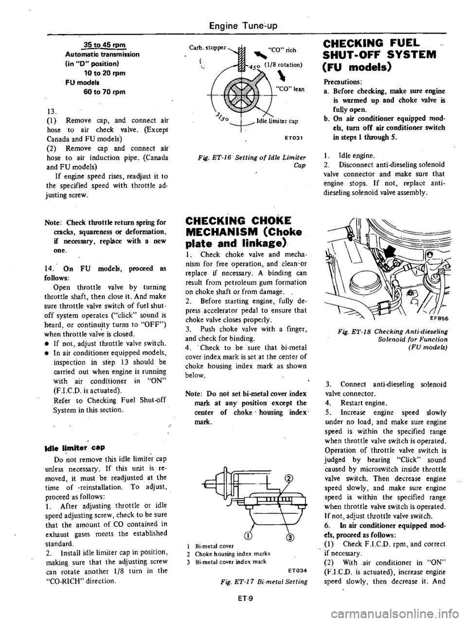
Fig
ET
16
Setting
of
Idle
Limiter
Cap
CHECKING
CHOKE
MECHANISM
Choke
plate
and
linkage
I
Check
choke
valve
and
mecha
nism
for
free
operation
and
clean
or
replace
if
necessary
A
binding
can
result
from
petroleum
gum
formation
on
choke
shaft
or
from
damage
2
Sefore
starting
engine
fully
de
press
accelerator
pedal
to
ensure
that
choke
valve
closes
properly
3
Push
choke
valve
with
a
finger
and
check
for
binding
4
Check
to
be
sure
that
bi
metal
cover
index
mark
is
set
at
the
center
of
choke
housing
index
mark
as
shown
below
Note
Do
not
set
bi
metal
cover
index
mark
at
any
position
except
the
center
of
choke
housing
index
mark
tfljlL
L
i
05
1
Hi
metal
cover
2
Choke
housing
ind
x
marks
3
Hi
metal
cover
index
mark
ET034
Fig
ET
17
Bi
metal
Setting
ET
9
CHECKING
FUEL
SHUT
OFF
SYSTEM
FU
models
Precautions
a
Before
checking
make
sure
engine
is
warmed
up
and
choke
valve
is
fully
open
b
On
air
conditioner
equipped
mod
els
turn
off
air
conditioner
switch
in
steps
I
through
S
Idle
engine
2
Disconnect
anti
dieseling
solenoid
valve
connector
and
make
sure
that
engine
stops
If
not
replace
anti
dieseling
solenoid
valve
assembly
Fig
ET
18
Checking
Anti
dieseling
Solenoid
for
Function
FU
models
3
Connect
anti
dieseling
solenoid
valve
connector
4
Restart
engine
S
Increase
engine
speed
slowly
under
no
load
and
make
sure
engine
speed
is
within
the
specified
range
when
throttle
valve
switch
is
operated
Operation
of
throttle
valve
switch
is
judged
by
hearing
Click
sound
caused
by
microswitch
inside
throttle
valve
switch
Then
decrease
engine
speed
slowly
and
make
sure
engine
speed
is
within
the
specified
range
when
throttle
valve
switch
is
operated
If
not
adjust
throttle
valve
switch
6
In
air
conditioner
equipped
mod
els
proceed
as
follows
1
Check
F
1
C
D
rpm
and
correct
if
necessary
2
With
air
conditioner
in
ON
F
l
C
D
is
actuated
increase
engine
speed
slowly
then
decrease
it
And
Page 24 of 548
make
sure
throttle
valve
operates
click
sound
is
heard
or
continuity
turns
to
OFF
when
engine
speed
decrease
to
idling
If
not
adjust
throttle
valve
switch
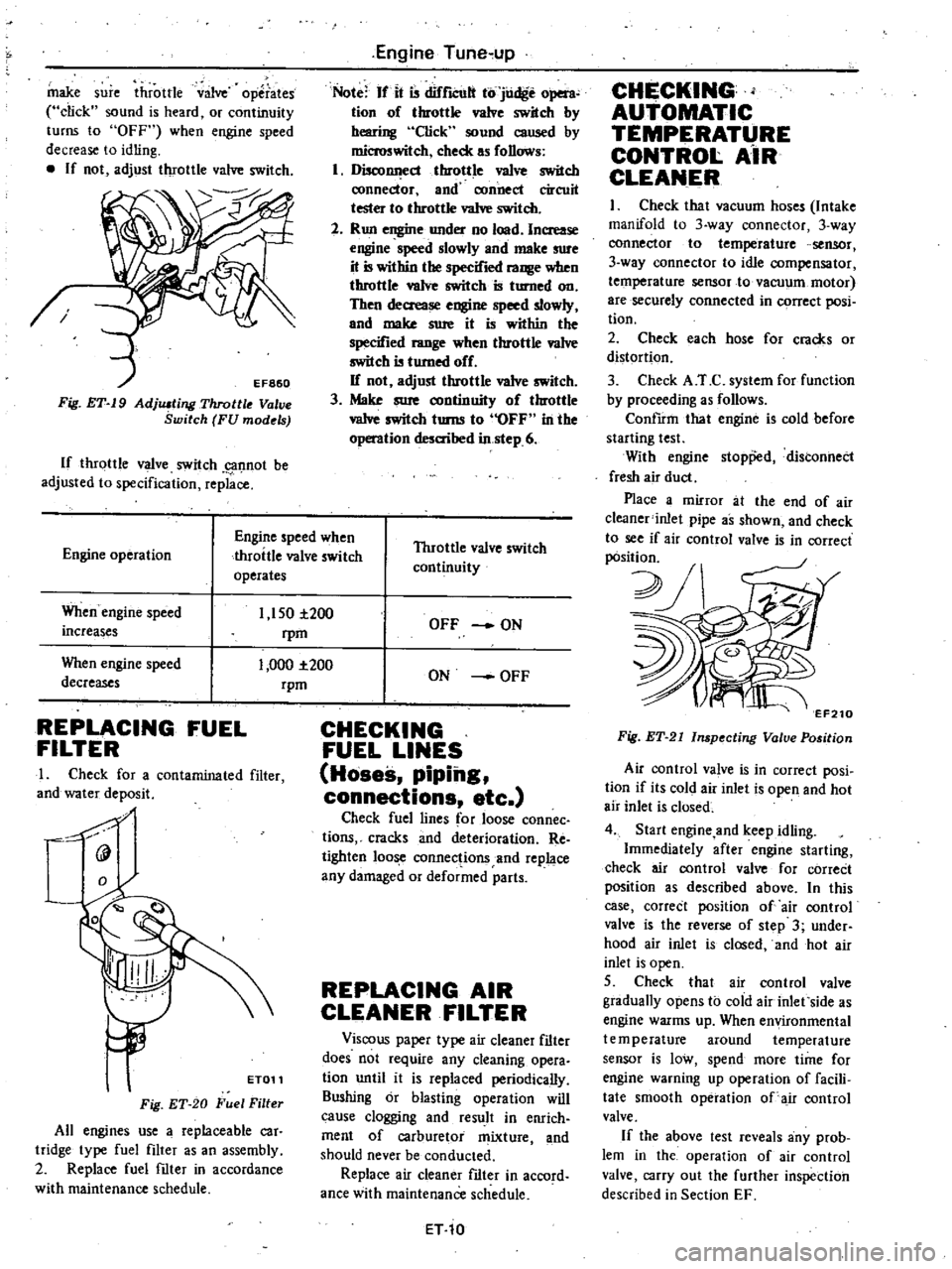
Fig
ET
19
AdjlUting
Throttle
V
ve
Switch
FU
models
If
throttle
valve
switch
g1f1not
be
adjusted
to
specification
replace
Engine
Tune
up
Note
If
it
is
difrlCUlt
to
judge
open
tion
of
throttle
valve
switch
by
hearing
Click
sound
caused
by
microswitch
check
as
follows
1
DiscollI
ecl
throttle
va1ve
switch
ronnector
and
connect
circuit
tester
to
throttle
va1ve
switch
2
Run
engine
under
no
load
Increase
engine
speed
slowly
and
make
sure
it
is
within
the
specified
range
when
throttle
valve
switch
is
turned
on
Then
decrease
engine
speed
slowly
and
make
sure
it
is
within
the
specified
range
when
throttle
va1ve
switch
is
turned
off
If
not
adjust
throttle
valve
switch
3
Make
sure
continuity
of
throttle
vaIve
switch
turns
to
OFF
in
the
operation
desaihed
in
step
6
Engine
operation
Engine
speed
when
throttle
valve
switch
operates
Throttle
valve
switch
continuity
When
engine
speed
increases
1
150
i200
rpm
1
000
1
200
rpm
When
engine
speed
decreases
REPLACING
FUEL
FILTER
I
Check
for
a
contaminated
filter
and
water
deposit
0
9
ET011
Fig
ET
20
Fuel
Filter
All
engines
use
a
replaceable
car
tridge
type
fuel
filter
as
an
assembly
2
Replace
fuel
filter
in
accordance
with
maintenance
schedule
OFF
ON
ON
OFF
CHECKING
FUEL
LINES
Hoses
piping
connections
etc
Check
fuel
lines
for
loose
connec
tions
cracks
and
deterioration
Re
tighten
loose
connections
and
replace
any
damaged
or
deformed
parts
REPLACING
AIR
CLEANER
FILTER
Viscous
paper
type
air
cleaner
filter
does
not
require
any
cleaning
opera
tion
until
it
is
replaced
periodically
Sushing
or
blasting
operation
will
cause
clogging
and
result
in
enrich
ment
of
carburetor
mixture
and
should
never
be
conducted
Replace
air
cleaner
filter
in
accord
ance
with
maintenance
schedule
ET
10
CHECKING
AUTOMATIC
TEMPERATURE
CONTROl
AiR
CLEANER
I
Check
that
vacuum
hoses
Intake
manifold
to
3
way
connector
3
way
connector
to
temperature
sensor
3
way
connector
to
idle
compensator
temperature
sensor
to
vacuum
motor
are
securely
connected
in
C9rrect
posi
tion
2
Check
each
hose
for
cracks
or
distortion
3
Check
A
T
C
system
for
function
by
proceeding
as
follows
ConfIrm
that
engine
is
cold
before
starting
test
With
engine
stopp
d
distonnect
fresh
air
duct
Place
a
mirror
at
the
end
of
air
c1eaner
inlet
pipe
as
shown
and
check
to
see
if
air
control
valve
is
in
correct
pOsition
2J
v
7
EF210
Fig
ET
21
Inspecting
Valve
Position
Air
control
va
ve
is
in
correct
posi
tion
if
its
cold
air
inlet
is
open
and
hot
air
inlet
is
closed
4
Start
engine
and
keep
idling
Immediately
after
engine
starting
check
air
control
valve
for
correCt
position
as
described
above
In
this
case
correct
position
of
air
control
valve
is
the
reverse
of
step
3
under
hood
air
inlet
is
closed
and
hot
air
inlet
is
open
5
Check
that
air
control
valve
gradually
opens
to
cold
air
inlet
side
as
engine
warms
up
When
environmental
temperature
around
temperature
sensor
is
low
spend
more
time
for
engine
warning
up
operation
of
facili
tate
smooth
operation
of
air
control
valve
If
the
above
test
reveals
any
prob
lem
in
the
operation
of
air
control
valve
carry
out
the
further
inspection
described
in
Section
EF
Page 89 of 548
TEMPERATURE
SENSOR
Removal
I
Using
pliers
flatten
clip
con
necting
vacuum
hose
to
sensor
vacuum
tube
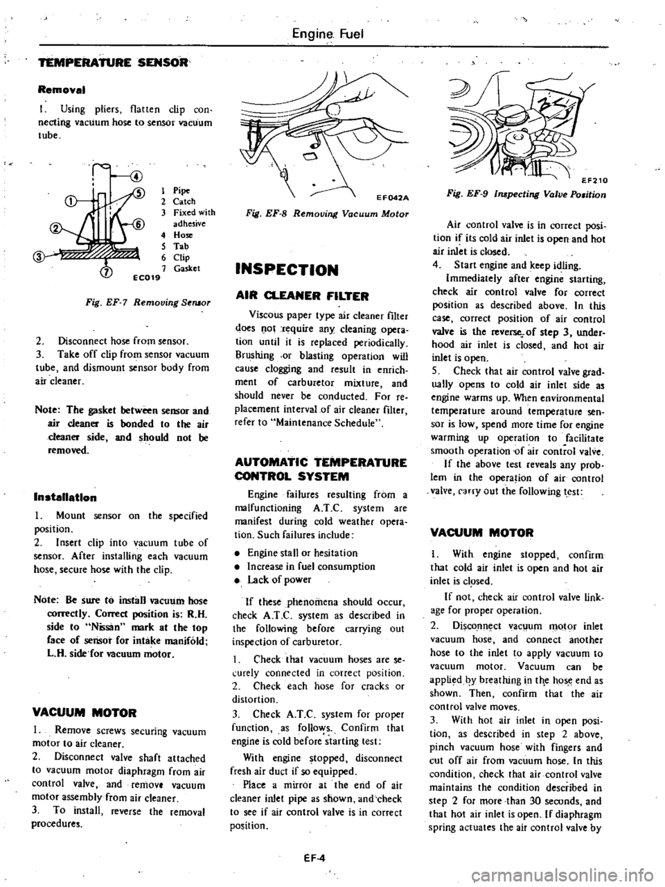
1
Pipe
2
Catch
3
Fixed
with
adhesive
4
Hose
5
Tab
6
Clip
7
Gasket
EC019
Fig
EF
7
Removing
Seruor
2
Disconnect
hose
from
sensor
3
Take
off
clip
from
sensor
vacuum
tube
and
dismount
sensor
body
from
air
cleaner
Note
The
gasket
between
sensor
and
air
cleaner
is
bonded
to
the
air
cleaner
side
and
should
not
be
removed
Installation
Mount
sensor
on
the
specified
position
2
Insert
clip
into
vacuum
tube
of
sensor
After
installing
each
vacuum
hose
secure
hose
with
the
clip
Note
Be
sure
to
install
vacUl
11n
hose
correctly
Correct
position
is
R
H
side
to
Ntisan
mark
at
the
top
face
of
sensor
for
intake
manifold
L
H
side
for
Deuum
motor
VACUUM
MOTOR
1
Remove
screws
securing
vacuum
motor
to
air
cleaner
2
Disconnect
valve
shaft
attached
to
vacuum
motor
diaphragm
from
air
control
valve
and
remove
vacuum
motor
assembly
from
air
cleaner
3
To
install
reverse
the
removal
procedures
Engine
Fuel
Fig
EF
8
Removing
Vacuum
Motor
INSPECTION
AIR
CLEANER
FILTER
Viscous
paper
type
air
cleaner
filter
does
o
ot
rt
quire
any
cleaning
opera
tion
until
it
is
replaced
periodically
Brushing
or
blasting
operation
will
cause
clogging
and
result
in
enrich
ment
of
carburetor
mixture
and
should
never
be
conducted
For
reo
placement
interval
of
air
cleaner
filter
refer
to
Maintenance
Schedule
AUTOMATIC
TEMPERATURE
CONTROL
SYSTEM
Engine
failures
resulting
from
a
malfunctioning
A
T
C
system
are
manifest
during
cold
weather
opera
tion
Such
failures
include
Engine
stall
or
hesitation
Increase
in
fuel
consumption
Lack
of
power
If
these
phenomena
should
occur
check
A
T
e
system
as
described
in
the
following
before
carrying
out
inspection
of
carburetor
I
Check
that
vacuum
hoses
are
se
l
urely
connected
in
correct
position
2
Check
each
hose
for
cracks
or
distortion
3
Check
A
T
C
system
for
proper
function
as
follo
ys
Confirm
that
engine
is
cold
before
starting
test
With
engine
topped
disconnect
fresh
air
duct
if
so
equipped
Place
a
mirror
at
the
end
of
air
cleaner
inlet
pipe
as
shown
and
check
to
see
if
air
control
valve
is
in
correct
position
EF
4
Fig
EF
9
Inspecting
Valve
Po
man
Air
control
valve
is
in
correct
posi
tion
if
its
cold
air
inlet
is
open
and
hot
air
inlet
is
closed
4
Start
engine
and
keep
idling
Immediately
after
engine
starting
check
air
control
valve
for
correct
position
as
described
above
In
this
case
correct
position
of
air
control
valve
is
the
reverse
of
step
3
under
hood
air
inlet
is
closed
and
hot
air
inlet
is
open
S
Check
that
air
control
valve
grad
ually
opens
to
cold
air
inlet
side
as
engine
warms
up
When
environmental
temperature
around
temperature
sen
sor
is
low
spend
more
time
for
engine
warming
up
operation
to
facilitate
smooth
operation
of
air
control
valve
If
the
above
test
reveals
any
prob
lem
in
the
opera
ion
of
air
control
valve
carry
out
the
following
test
VACUUM
MOTOR
I
With
engine
stopped
confirm
that
cold
air
inlet
is
open
and
hot
air
inlet
is
c1
Sed
If
not
check
air
control
valve
link
age
for
proper
operation
2
DiscoJln
ct
ac
um
motor
inlet
vacuum
hose
and
connect
another
hose
to
the
inlet
to
apply
vacuum
to
vacuum
motor
Vacuum
can
be
appli
d
by
breathing
in
tile
hos
e
end
as
shown
Then
confirm
that
the
air
control
valve
moves
3
With
hot
air
inlet
in
open
posi
tion
as
described
in
step
2
above
pinch
vacuum
hose
with
fingers
and
cut
off
air
from
vacuum
hose
In
this
condition
check
that
air
control
valve
maintains
the
condition
described
in
step
2
for
more
than
30
seconds
and
that
hot
air
inlet
is
open
If
diaphragm
spring
actuates
the
air
control
valve
by
Page 92 of 548
5
The
pressure
gauge
indicates
static
fuel
pressure
in
the
line
The
gauge
reading
should
be
within
the
specified
value
Fuel
pump
pressure
0
21
to
0
27
kg
em2
3
0
to
3
8
pli
I
Note
If
the
fuel
in
the
carburetor
float
chamber
has
run
out
and
engine
has
stopped
remove
clip
and
pour
fuel
into
carburetor
Fasten
clip
securely
and
repeat
static
pres
sure
test
If
pressure
is
not
within
the
specifi
ed
limit
remove
pump
as
an
assembly
CAPACITY
TEST
The
capacity
test
is
conducted
only
when
static
pressure
is
within
the
specification
To
conduct
this
test
proceed
as
follows
1
Disconnect
pressure
gauge
from
T
connector
and
in
its
vacant
place
install
a
suitable
container
as
a
fuel
sump
2
Start
engine
and
run
at
1
000
pm
3
Pump
should
deliver
the
specified
amouni
of
fuel
If
little
or
no
fuel
flows
from
open
end
of
pipe
it
is
an
indication
that
fuel
line
is
clogged
or
pump
is
mal
functioning
Fuel
pump
capacity
450
cc
27
46
eu
inl
min
at
1
000
rpm
REMOVAL
AND
INSTALLATION
Note
When
disconnecting
fuel
lines
use
a
container
to
receive
fuel
remaining
in
fuel
hoses
I
Disconnect
inlet
and
outlet
fuel
hoses
from
fuel
pump
2
Remove
fuel
pump
3
To
install
reverse
the
order
of
removal
Engine
Fuel
DISASSEMBLY
@@
@@
@
@@
1
Remove
screws
and
detach
upper
and
lower
bodies
2
Remove
screws
and
take
off
cap
and
cap
gasket
from
upper
body
3
Remove
inlet
and
outlet
connee
tors
4
Remove
valve
retainer
screws
and
take
off
valve
retainer
S
To
remove
diaphragm
press
down
its
center
against
spring
force
With
diaphragm
pressed
down
ilt
it
until
end
of
pull
rod
touches
inner
wall
of
body
Then
release
diaphragm
to
unhook
push
rod
Note
Be
careful
not
to
damage
dia
phragm
or
oil
seal
INSPECTION
Check
all
components
for
cracks
EF
7
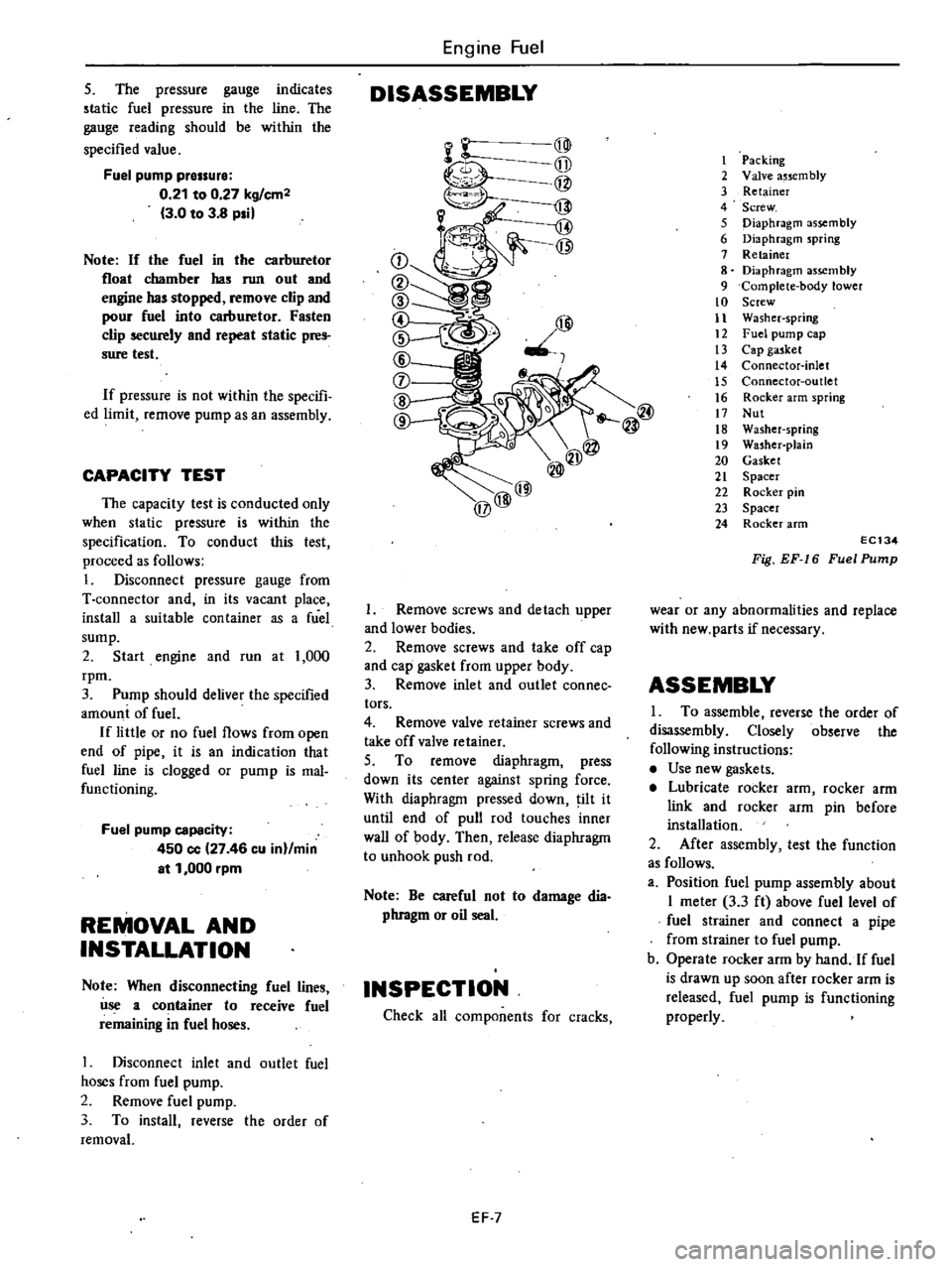
I
Packing
2
Valve
a5scm
bly
3
Retainer
4
Screw
5
Diaphragm
assembly
6
Diaphragm
spring
7
Retainer
8
Diaphragm
assembly
9
Complete
body
lower
10
Screw
11
Washer
spring
12
Fuel
pump
cap
13
Cap
gasket
14
Connector
inlet
15
Connector
outlet
16
Rocker
arm
spring
17
Nut
18
Washer
spring
19
Washer
pJain
20
Gasket
21
Spacer
22
Rocker
pin
23
Spacer
24
Rocker
arm
EC134
Fig
EF
16
Fuel
Pump
wear
or
any
abnormalities
and
replace
with
new
parts
if
necessary
ASSEMBLY
I
To
assemble
reverse
the
order
of
disassembly
Closely
observe
the
following
instructions
Use
new
gaskets
Lubricate
rocker
arm
rocker
arm
link
and
rocker
arm
pin
before
installation
2
After
assembly
test
the
function
as
follows
a
Position
fuel
pump
assembly
about
I
meter
3
3
ft
above
fuel
level
of
fuel
strainer
and
connect
a
pipe
from
strainer
to
fuel
pump
b
Operate
rocker
arm
by
hand
If
fuel
is
drawn
up
soon
after
rocker
arm
is
released
fuel
pump
is
functioning
properly
Page 101 of 548
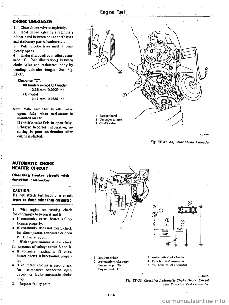
CHOKEUNLOADER
I
Close
choke
valve
completely
2
Hold
choke
valve
by
stretching
a
rubber
band
between
choke
shaft
lever
and
stationary
part
of
carllUretor
3
Pull
throttle
lever
until
it
com
pletely
opens
4
Under
this
condition
adjust
clear
ance
e
See
illustration
between
choke
valve
and
carburetor
body
by
bending
unloader
tongue
See
Fig
EF
37
Clearance
C
All
modelS
ex
pt
F
U
model
2
36
mm
0
0929
in
FU
model
2
17
mm
0
0854
in
Note
Make
sure
that
throttle
valve
opensfuDy
when
carburetor
is
mounted
on
car
If
throttle
valve
fails
to
open
fully
unloader
becomes
inoperative
re
suiting
in
poor
acceleration
after
engine
is
started
AUTOMATIC
CHOKE
HEATE
IRCUIT
Checking
heater
circuit
with
function
connector
CAUTION
00
not
attach
test
leads
of
8
circuit
tester
to
those
other
than
designated
I
With
engine
not
running
check
for
continuity
between
A
and
B
If
continuity
exists
heater
is
fune
tioning
properly
If
continuity
does
not
exist
check
for
discon
nected
connector
or
open
P
T
C
heater
circuit
2
With
engine
running
at
idle
check
for
presence
of
voltage
across
A
and
B
If
voltmeter
reading
is
12
volts
heater
circuit
is
functioning
proper
ly
If
voltmeter
reading
is
zero
check
for
disconnected
connector
open
circuit
or
faulty
automatic
choke
relay
3
Replace
faulty
parts
Engine
Fuel
c
i
CD
1
Rubber
band
2
Unloa
er
tongue
3
Choke
vaJve
f
rC
EC150
Fig
EF
37
Adjusting
Choke
Unloader
SJ
v
1
Ignition
switch
2
Automatic
choke
relay
Engine
stop
ON
Engine
start
OFF
3
Automatic
choke
heater
4
Function
test
connector
5
L
terminal
of
alternator
EF
16
Fig
EF
38
EF433A
Checking
Automatic
Choke
Heater
Circuit
with
Function
Teat
Connector
Page 103 of 548
Engine
Fuel
Upon
completion
of
adjustment
make
sure
that
link
system
opera
tes
smoothly
It
is
necessary
to
remove
Carburetor
from
engine
in
adjusting
this
accelera
tor
pump
stroke
limiter
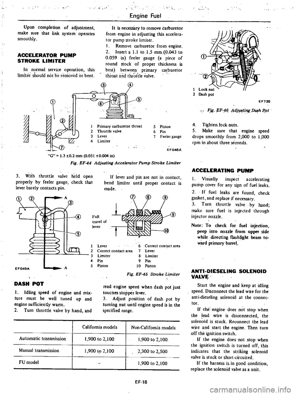
1
Remove
carburetor
from
engine
2
Insert
a
l
l
to
I
S
mm
0
043
to
0
059
in
feeler
gauge
a
piece
of
round
stock
of
proper
thickness
is
best
betwee
l
primary
ca
buretor
throat
and
throtile
valve
ACCELERATOR
PUMP
STROKE
LIMITER
In
rmal
service
operation
this
limiter
should
not
be
removed
or
bent
In
J
0
ID
@
l
1IJl
J
J
00
I
f
oj
G
1
3
IO
2
mm
0
051
IO
004
in
Fig
EF
44
AdjlUting
Acce
rator
Pump
Stroke
Limiter
1
Primary
carburetor
throat
2
Throttle
valve
3
Lever
4
Limiter
5
Piston
6
Pin
7
Feeler
gauge
E
F048A
3
With
throttle
valve
held
open
properly
by
feeler
gauge
check
that
lever
barely
contacts
pin
If
lever
and
pin
are
not
in
contact
bend
limiter
until
proper
contact
is
made
OZ
00
A
fID
1
S
@
4
1
Full
travel
of
lever
f
EF049A
A
1
Lever
2
Correct
contact
area
3
Limiter
4
Pin
5
Pistgn
6
Correct
cont
ct
area
7
Lever
8
Limiter
9
Pin
10
Piston
Fig
EF
45
Stroke
Limiter
DASH
POT
I
Idling
speed
of
engine
and
mix
ture
must
be
well
tuned
up
and
engine
sufficiently
warm
2
Turn
throttle
valve
by
hand
and
read
engine
speed
when
dash
pot
just
toucnes
stopper
lever
3
Adjust
position
of
dash
pot
by
tuming
nut
until
engine
speed
is
in
the
specified
range
California
models
Non
Califomia
models
Automatic
transmission
1
900
to
2
100
1
900
to
2
100
Manual
transmission
1
900
tp
2
100
2
300
to
2
500
FU
model
1
900
to
2
100
EF
t8
1
Lock
nut
2
Dash
pot
E
F730
F
ig
EF
4
Ll
dj
ting
h
P
ot
4
Tighten
lock
nuts
5
Make
sure
that
engine
speed
drops
smoothly
from
2
000
to
1
000
rpm
in
about
three
seconds
ACCELERATING
PUMP
I
Visually
inspect
accelerating
pump
cover
for
any
sign
of
fuel
leaks
2
If
fuel
leaks
are
found
check
gasket
and
replace
if
necessary
3
Turn
throttle
valve
by
hand
make
sure
fuel
is
injected
through
injector
nozzle
Note
To
check
or
fuel
injection
peep
into
nozzle
rom
upper
side
while
directing
flashlight
beam
to
ward
primary
barrel
ANTI
DIESELING
SOLENOID
VALVI
Start
the
engine
and
keep
at
idling
speed
Disconnect
the
lead
w
e
for
the
anti
dieseling
solenoid
at
the
connec
tor
If
the
engine
does
not
stop
when
the
lead
wire
is
disconnected
the
solenoid
is
stuck
Reconnect
the
lead
wire
and
start
the
engine
Then
turn
off
the
ignition
switch
If
the
engine
does
not
stop
when
the
ignition
switch
is
turned
off
this
indicates
that
the
striking
solenoid
valve
is
stuck
or
short
circuited
If
the
harness
i
in
good
condition
replace
the
solenoid
valve
as
a
unit
Page 107 of 548
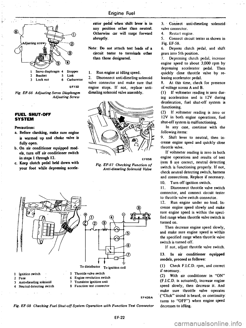
1
Servo
diaphragm
4
Stopper
2
Bracket
5
Link
3
Lock
nut
6
Carburetor
EF732
Fig
EF
56
Adjusting
Seroo
Diaphragm
Adjwting
Screw
FUEL
SHUT
OFF
SYSTEM
Precautions
a
Before
checking
make
sure
engine
is
warmed
up
and
choke
wive
is
fully
open
b
On
air
conditioner
equipped
mod
els
turn
off
air
conditioner
switch
in
steps
I
through
12
c
Keep
clutch
pedal
held
down
with
your
foot
while
depressing
accele
g
f
J
1
Engine
Fuel
rator
pedllI
when
shift
leVer
ISm
any
position
other
than
neutral
Otherwise
car
will
surge
forward
abruptly
Note
Do
not
attach
test
leads
of
a
circuit
tester
to
terminals
other
than
those
designated
Run
engine
at
idling
speed
2
Disconnect
anti
dieseling
solenoid
valve
connector
and
make
sure
that
engine
stops
If
not
replace
anti
dieseling
solenoid
valve
assembly
EF856
Fig
EF
57
Checking
Function
of
Anti
die
eling
Solenoid
Valve
31
A
t
CID
@
V
II
l
To
distributor
T
n
l1on
coon
o
1
Ignition
switch
2
Fuse
3
Anti
dieseling
solenoid
4
Neu
tral
detecting
switch
5
Throttle
valve
swltch
6
Engine
revolution
switch
7
Transistor
ignition
unit
8
Function
test
connector
Fig
EF
58
Checking
Fuel
Shut
off
System
Operation
with
Function
Test
Connector
EF436A
EF
22
3
Conilect
anti
ieselingsolenoid
valve
connector
4
Restart
engine
5
Connect
circuit
tester
as
shown
in
Fig
EF
S8
6
Depress
clutch
pedal
and
shift
gears
into
5th
position
7
Depressing
clutch
pedal
increase
engine
speed
to
about
3
000
rpm
by
depressing
accelerator
pedal
Then
quickly
close
throttle
wIve
by
re
leasing
accelerator
pedal
8
At
this
time
check
for
presence
of
voltage
across
A
and
B
I
If
voltmeter
reading
i
ero
dur
ing
acceleration
and
is
12V
during
deceleration
fuel
shut
off
system
is
functioning
2
If
voltmeter
reading
is
zero
or
l2V
in
both
engine
operations
fuel
shut
off
system
is
malfunctioning
In
any
case
continue
with
the
following
items
9
Shift
lever
to
neutral
then
in
crease
engine
speed
and
quickly
close
throttle
valve
If
voltmeter
reading
is
zero
in
both
engine
operations
and
results
of
test
i
tern
8
are
correct
neutral
detecting
switch
is
functioning
properly
If
not
check
neutral
detecting
switch
harness
and
connections
Replace
if
necessary
10
Turn
off
ignition
switch
II
Disconnect
throttle
valve
switch
connector
and
connect
circuit
tester
to
throttle
valve
switch
connector
12
Run
engine
under
no
load
In
crease
engine
speed
slowly
and
make
sure
engine
speed
is
within
the
speci
fied
range
when
throttle
valve
switch
is
turned
on
Then
decrease
engine
speed
slowly
and
make
sure
engine
speed
is
within
the
specified
range
when
throttle
valve
switch
is
turned
off
If
not
adjust
throttle
valve
switch
13
In
air
conditioner
equipped
models
proceed
as
follows
I
Check
F
l
C
D
rpm
and
correct
if
necessary
2
With
air
conditioner
in
ON
F
l
C
D
is
actuated
increase
engine
speed
slowly
then
decrease
it
And
make
sure
throttle
valve
operates
Click
sOund
is
heard
or
continuity
turns
to
OFF
when
engine
speed
decreases
to
idling
Page 128 of 548
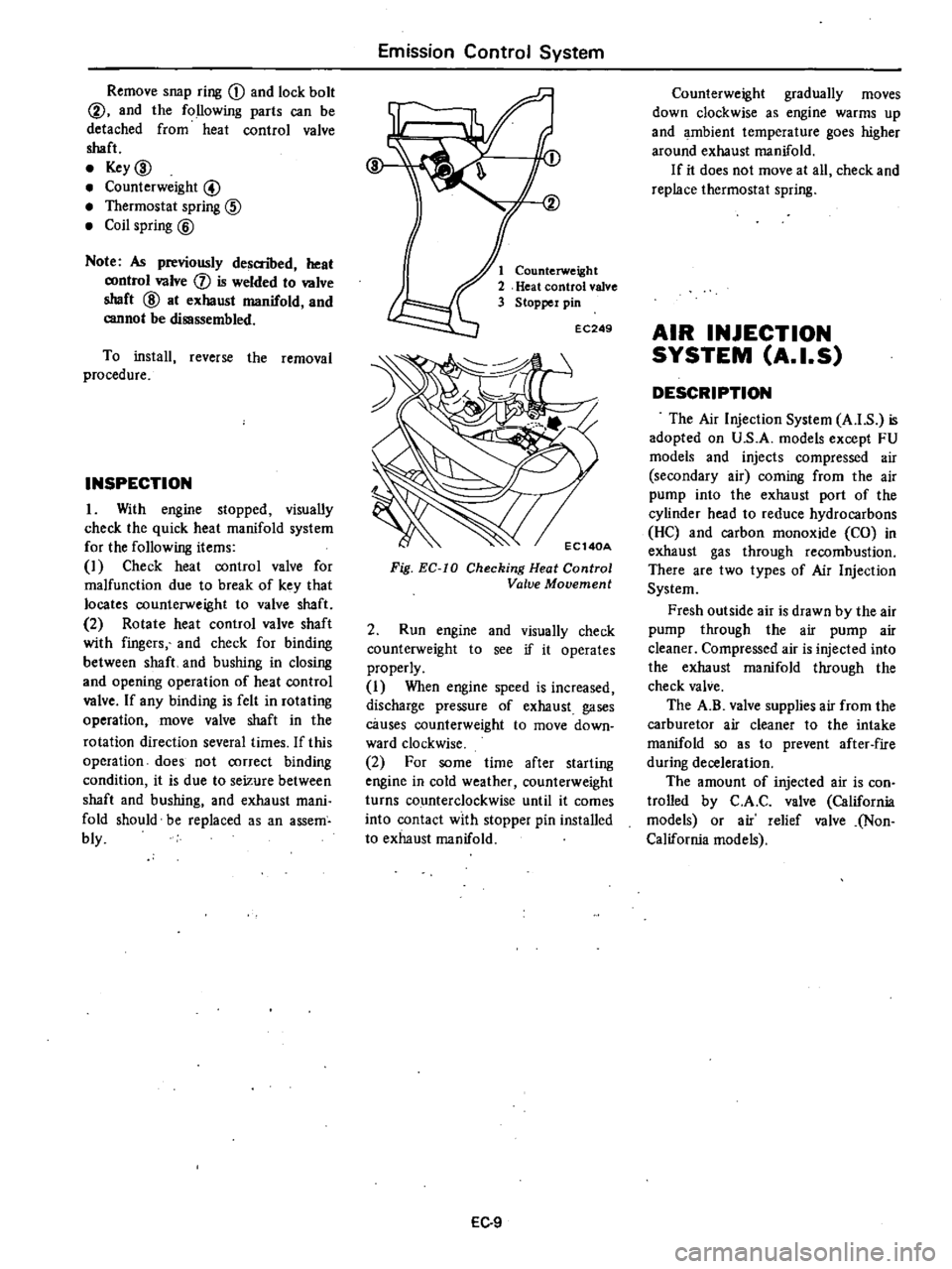
Remove
snap
ring
CD
and
lock
bolt
@
and
the
following
parts
can
be
detached
from
heat
control
valve
shaft
Key
ID
Counterweight
@
Thermostat
spring
@
Coil
spring
@
Note
As
previously
descnbed
heat
control
valve
j
is
welded
to
valve
shaft
@
at
exhaust
manifold
and
cannot
be
disassembled
To
install
reverse
the
removal
procedure
INSPECTION
1
With
engine
stopped
visually
check
the
quick
heat
manifold
system
for
the
following
items
I
Check
heat
control
valve
for
malfunction
due
to
break
of
key
that
locates
counterweight
to
valve
shaft
2
Rotate
heat
control
valve
shaft
with
fingers
and
check
for
binding
between
shaft
and
bushing
in
closing
and
opening
operation
of
heat
control
valve
If
any
binding
is
felt
in
rotating
operation
move
valve
shaft
in
the
rotation
direction
several
times
If
this
operation
does
not
correct
binding
condition
it
is
due
to
seizure
between
shaft
and
bushing
and
exhaust
mani
fold
should
be
replaced
as
an
assem
bly
Emission
Control
System
Counterweight
Heat
control
valve
Stopper
pin
EC249
Fig
EC
IO
Checking
Heat
Control
Valve
Movement
2
Run
engine
and
visually
check
counterweight
to
see
if
it
operates
properly
I
When
engine
speed
is
increased
discharge
pressure
of
exhaust
gases
causes
counterweight
to
move
down
ward
clockwise
2
For
some
time
after
starting
engine
in
cold
weather
counterweight
turns
counterclockwise
until
it
comes
into
contact
with
stopper
pin
installed
to
exhaust
manifold
EC
9
Counterweight
gradually
moves
down
clockwise
as
engine
warms
up
and
ambient
temperature
goes
higher
around
exhaust
manifold
If
it
does
not
move
at
all
check
and
replace
thermostat
spring
AIR
INJECTION
SYSTEM
A
I
S
DESCRIPTION
The
Air
Injection
System
A
I
S
is
adopted
on
U
S
A
models
except
FU
models
and
injects
compressed
air
secondary
air
coming
from
the
air
pump
into
the
exhaust
port
of
the
cylinder
head
to
reduce
hydrocarbons
He
and
carbon
monoxide
CO
in
exhaust
gas
through
recombustion
There
are
two
types
of
Air
Injection
System
Fresh
outside
air
is
drawn
by
the
air
pump
through
the
air
pump
air
cleaner
Compressed
air
is
injected
into
the
exhaust
manifold
through
the
check
valve
The
A
B
valve
supplies
air
from
the
carburetor
air
cleaner
to
the
intake
manifold
so
as
to
prevent
after
fire
during
deceleration
The
amount
of
injected
air
is
con
trolled
by
C
A
C
valve
California
models
or
air
relief
valve
Non
California
models
Page 163 of 548
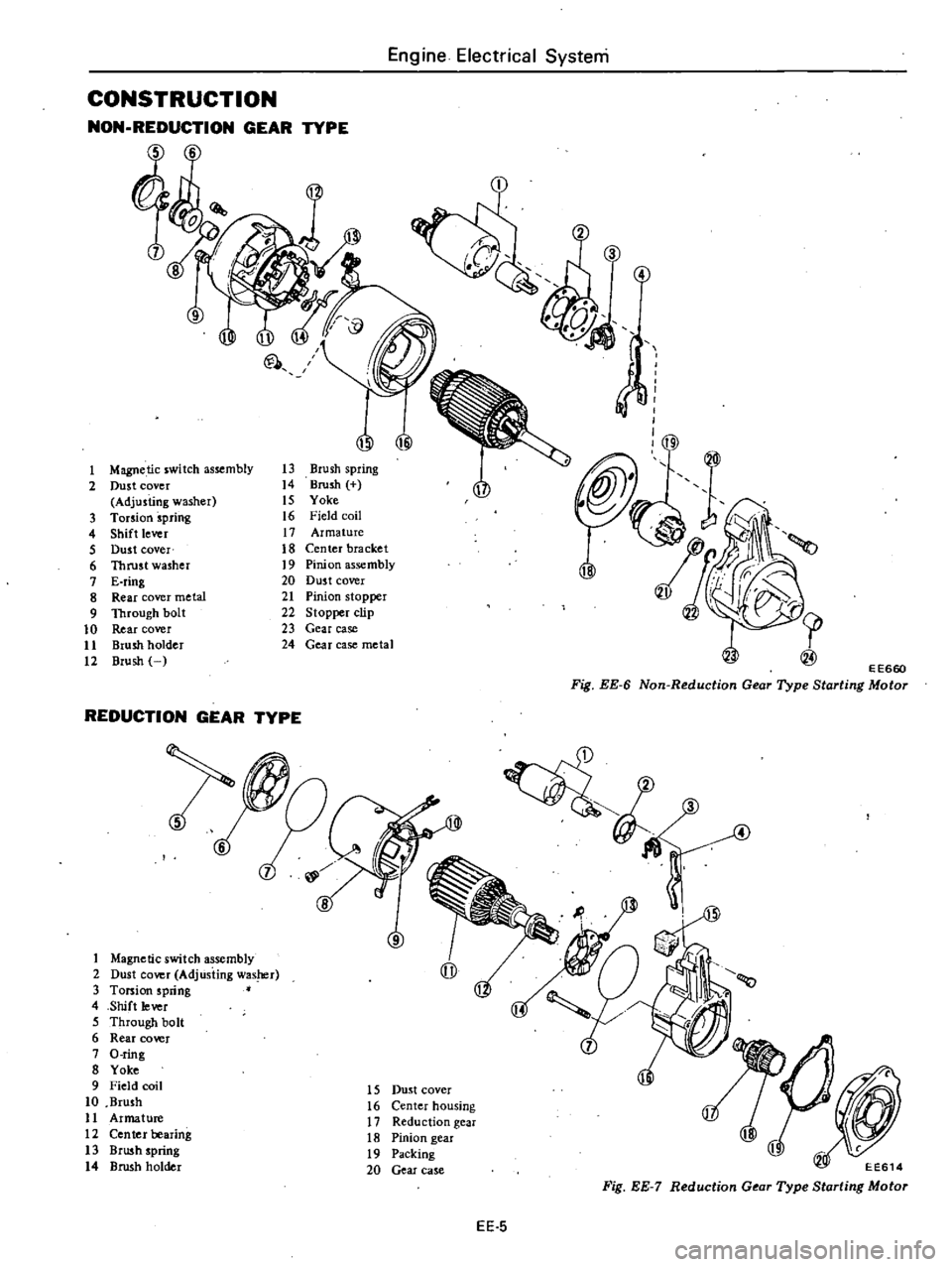
CONSTRUCTION
NON
REDUCTION
GEAR
TYPE
6
00
1
Magnetic
switch
assembly
2
Dust
cover
Adjusting
washer
3
Torsion
spring
4
Shift
lever
5
Dust
cover
6
Thrust
washer
7
E
ring
8
Rear
cover
metal
9
Through
bolt
10
Rear
cover
11
Brush
holder
12
Brush
U
Ul
@
13
Brush
spring
14
Brush
IS
Yoke
16
Field
coil
17
Armature
18
Center
bracket
19
Pinion
assembly
20
Dus
t
cover
21
Pinion
stopper
22
Stopper
clip
23
Gear
case
24
Gear
case
metal
REDUCTION
GEAR
TYPE
1
Magnetic
switch
assembly
2
Dust
cover
AdjUsting
was
r
3
Torsion
spring
4
Shift
lever
5
Through
bolt
6
Rear
cover
7
O
ring
8
Yoke
9
Field
coil
10
Brush
11
Armature
12
Ceo
tel
bearing
13
Brush
spring
14
Brush
holder
6
8
Engine
Electrical
Systeni
3
@
1
E
E660
Fig
EE
6
Non
Reduction
Gear
Type
Starting
Motor
4
4
15
Dust
cover
16
Center
housing
17
Reduction
gear
18
Pinion
gear
19
Packing
20
Gear
case
EE614
Fig
EE
7
Reduction
Gear
Type
Starting
Motor
EE
5