stop start DATSUN 210 1979 User Guide
[x] Cancel search | Manufacturer: DATSUN, Model Year: 1979, Model line: 210, Model: DATSUN 210 1979Pages: 548, PDF Size: 28.66 MB
Page 164 of 548
REMOVAL
AND
INSTALLATION
Disconnect
battery
ground
cable
Disconnect
harness
connector
and
battery
cable
at
magnetic
switch
2
Remove
bolts
securing
starting
motor
to
transmission
case
Pull
start
iog
motor
forward
and
remove
it
3
Inst
1I
starting
motor
in
reverse
order
of
removal
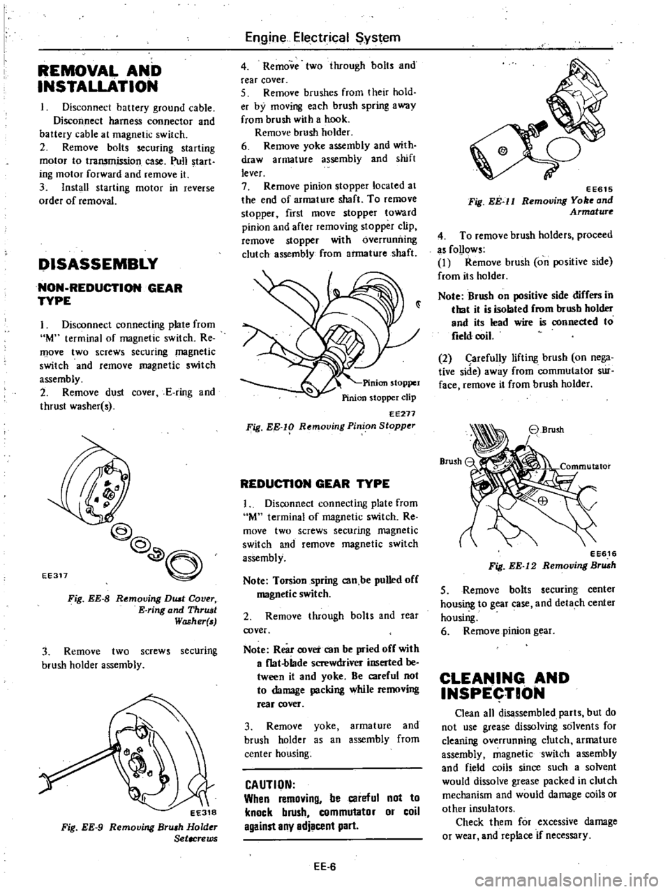
DISASSEMBLY
NON
REDUCTION
GEAR
TYPE
I
Disconnect
connecting
plate
from
M
terminal
of
magnetic
switch
Re
move
two
screws
securing
magnetic
switch
and
remove
magnetic
switch
assembly
2
Remove
dust
cover
E
ring
and
thrust
washer
s
EE311
@@
O
Fig
EE
8
Removing
DUll
Cover
E
ring
and
ThrUJJt
Washer
3
Remove
two
screws
securing
brush
holder
assembly
EE318
Fig
EE
9
Removing
Bru
h
Hold
Setacrews
Engine
Electrical
ystem
4
Remove
two
ihrough
bolts
and
rear
cover
5
Remove
brushes
from
their
hold
er
by
moving
each
brush
spring
away
from
brush
with
a
hook
Remove
brush
holder
6
Remove
yoke
assembly
and
with
draw
armature
assembly
and
shift
lever
7
Remove
pinion
stopper
located
at
the
end
of
armature
shaft
To
remove
stopper
first
move
stopper
toward
pinion
and
after
removing
stopper
clip
remove
stopper
with
overruniling
clutch
assembly
from
armature
shaft
EE271
Fig
EE
lg
Rf
moving
Pinion
Stopper
REDUCTION
GEAR
TYPE
1
Disconnect
connecting
plate
from
M
terminal
of
magnetic
switch
Re
move
two
screws
securing
magnetic
switch
and
remove
magnetic
switch
assembly
Note
Torsion
spring
can
be
pulled
off
magnetic
switch
2
Remove
through
baIts
and
rea
cover
Note
Rear
cover
can
be
pried
off
with
a
f1at
blade
screwdriver
inserted
be
tween
it
and
yoke
Be
careful
not
to
damage
packing
while
removing
reaf
cover
3
Remove
yoke
armature
and
brush
holder
as
an
assembly
from
center
housing
CAUTION
When
removing
be
careful
not
to
knock
brush
commutator
or
coil
against
any
adjacent
part
EE
6
o
7
EE615
Fig
EE
ll
Removing
Yo
and
Armature
4
To
remove
brush
holders
proceed
as
follows
I
Remove
brush
on
positive
side
from
its
holder
Note
Brush
on
positive
side
differs
in
that
it
is
isolated
from
brush
holder
and
its
lead
wire
is
connected
to
field
coil
2
Carefully
lifting
brush
on
nega
tive
side
away
from
commutator
sur
face
remove
it
from
brush
holder
EE616
Fig
EE
12
Removing
Br
h
5
Remove
bolts
securing
center
housing
to
gear
case
and
detach
center
housing
6
Remove
pinion
gear
CLEANING
AND
INSPECTION
Clean
all
disassembled
parts
but
do
not
use
grease
dissolving
solvents
for
cleaning
overrunning
clutch
armature
assembly
magnetic
switch
assembly
and
field
coils
since
such
a
solvent
would
dissolve
grease
packed
in
clutch
mechanism
and
would
damage
coils
or
other
insulators
Check
them
for
excessive
damage
or
wear
and
replace
if
necessary
Page 167 of 548
Starting
motor
S
DIAGNOSES
OF
TEST
I
Low
speed
with
no
load
and
high
current
draw
may
result
from
the
following
I
Tight
dirty
or
worn
bearings
2
Bent
armature
shaft
or
loosened
field
probe
3
Shorted
armature
Check
armature
further
4
A
grounded
armature
or
field
a
Remove
input
terminal
b
Raise
two
negative
side
brushes
from
commutator
c
Using
a
circuit
tester
place
one
probe
onto
input
terminal
and
the
other
onto
yoke
d
If
tester
indicates
continuity
raise
the
other
two
brushes
and
check
field
and
armature
separately
to
deter
mine
whether
field
or
armature
is
grounded
2
Failure
to
operate
with
high
cur
rent
draw
may
be
caused
by
the
following
I
A
grounded
or
open
field
coil
Inspect
the
connection
and
trace
circuit
with
a
circuit
tester
2
Armature
coil
does
not
operate
Inspect
commutator
for
excessive
burning
In
this
case
arc
may
occur
on
damaged
commutator
when
motor
is
operated
with
no
load
3
Burned
out
commutator
bar
Weak
brush
spring
tension
broken
Engine
Electrical
System
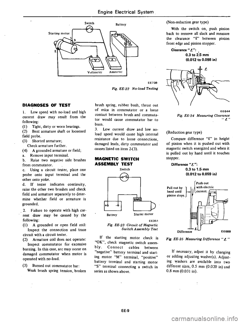
Switch
Battery
Vultmeter
Ammeter
EE738
Fig
EE
22
No
load
Testing
brush
spring
rubber
bush
thrust
out
of
mica
in
commuta
tor
or
a
loose
contact
between
brush
and
conunuta
tor
would
cause
commutator
bar
to
burn
3
Low
current
draw
and
low
no
load
speed
would
cause
high
internal
resistance
due
to
loose
connections
damaged
leads
dirty
commutator
and
causes
listed
on
item
2
3
MAGNETIC
SWITCH
ASSEMBLY
TEST
Switch
2
1
6
11
p
IB
b
I
Battery
Starter
motor
EE351
Fig
EE
23
Circuit
of
Magnetic
Switch
Assembly
Test
If
the
starting
motor
check
is
OK
check
magnetic
switch
assem
bly
Connect
cables
between
negative
battery
terminal
and
start
ing
motor
M
terminal
positive
battery
terminal
and
starting
motor
8
terminal
connecting
a
switch
in
series
as
shown
above
EE
9
Non
reduction
gear
type
With
the
switch
on
push
pinion
back
to
remove
all
slack
and
measure
the
clearance
between
pinion
front
edge
and
pinion
stopper
Clearance
L
0
3
to
2
5
mm
0
012
to
0
098
in
EE644
Fig
EE
24
Measuring
Clearance
l
Reduction
gear
type
Compare
difference
2
in
height
of
pinion
when
it
is
pushed
out
with
magnetic
switch
energized
and
when
it
is
pulled
out
by
hand
until
it
touches
stopper
Difference
L
0
3
to
1
5
mm
0
012
to
0
059
in
Pull
out
by
hand
until
pinion
stops
Push
out
1
1
n
11
r
L
Difference
EE688
Fig
EE
25
Measuri
g
Difference
L
If
necessary
adjust
it
by
changing
or
adding
adjusting
washer
s
Adjust
ing
washers
are
available
into
two
different
sizes
0
5
mm
0
020
in
and
0
8
mm
0
031
in
Page 190 of 548

Engine
Electrical
System
STARTING
MOTOR
Type
S1I4
160B
I
Sl14
163E
S114
253
Outer
diameter
of
commutator
mm
in
More
than
32
1
26
More
than
29
L14
Minimum
length
of
brush
mm
in
12
0
47
II
0
43
Brush
spring
tension
kg
Ib
1
4
to
1
8
3
1
to
4
0
1
6to
2
0
3
5
to
4
4
Clearance
between
bearing
metal
and
armature
shaft
mm
in
Less
than
0
2
0
008
Clearance
R
between
pinion
front
edge
and
pinioIl
stopper
mm
in
0
3
to
2
5
0
012
to
0
098
Difference
T
in
height
of
pinion
nun
in
0
3
to
1
5
0
012
to
0
059
ALTERNATOR
Type
LRI5049
Minimum
length
of
brush
mm
in
More
than
7
5
0
295
Brush
spring
pressure
gr
oz
255
to
345
8
99
to
12
17
Slip
ring
outer
diameter
nun
in
More
than
30
1
18
DISTRIBUTOR
Air
gap
mm
in
D4K8
19
I
D4K8
l3
I
D4K8
18
I
D4K8
02
D4K8
15
I
D4K8
16
0
3
to
0
5
0
012
to
0
020
Type
Cap
il1s
ation
resistance
M
1
More
than
50
Rotor
head
insulation
resistance
Mil
More
than
50
Cap
carbon
point
length
mm
in
10
0
39
Vacuum
advance
0
105
4
13
0
170
6
69
0
80
3
15
0
105
4
13
0
70
2
76
0
170
6
69
Distributor
degree
distributor
9
250
3
225
12
265
9
300
15
300
6
5
300
mmHg
inHg
9
84
8
86
10
43
11
81
11
81
11
81
Centrifugal
advance
0
550
6
550
0
550
0
550
0
750
0
750
Distributor
degree
distributor
14
2
300
14
2
300
13
5
2
400
13
5
2
400
10
2
400
10
2
400
rpm
EE
32
Page 214 of 548

Condition
Clutch
slips
Clutch
drags
Clutch
TROUBLE
DIAGNOSES
AND
CORRECTIONS
Probable
cause
and
testing
Corrective
action
Slipping
of
clutch
may
be
noticeable
when
any
of
the
following
symptoms
is
encountered
during
operation
I
Car
will
not
respond
to
erigine
speed
during
acceleration
2
Insufficient
car
speed
3
Lack
of
power
during
uphill
driving
Some
of
the
above
conditions
may
also
be
attributable
to
engine
problem
First
determine
whether
engine
or
clutch
is
causing
the
problem
If
slipping
clutch
is
left
unheeded
wear
and
or
overheating
will
occur
on
clutch
facing
to
such
an
extent
that
it
is
no
longer
serviceable
TO
TEST
FOR
SLIPPING
CLurCH
proceed
as
follows
During
upgrade
havelling
run
engine
at
about
40
to
50
km
h
25
to
31
MPH
with
gear
shift
lever
in
3rd
speed
position
shift
into
highest
gear
and
t
the
same
time
rev
up
engine
If
clutch
is
slipping
car
willnot
readily
respond
to
depression
of
accelerator
pedal
Clutch
facing
warn
excessively
Oil
or
grease
on
clutch
facing
Warped
clutch
cover
or
pressure
plate
Replace
Replace
Repair
or
replace
Dragging
clu
tch
is
particularly
noticeable
when
shifting
gears
especially
into
low
gear
TO
TEST
FOR
DRAGGING
CLurCH
proceed
as
follows
I
Start
engine
Disengage
clutch
Shift
into
reverse
gear
and
then
into
Neutral
Gradually
increase
engine
speed
and
again
shift
into
reverse
gear
If
clutch
is
dragging
gear
grating
is
heard
when
shifting
gears
from
Neutral
into
Reverse
2
Stop
engine
and
shift
gears
Conduct
this
test
at
each
gear
position
3
In
step
2
gears
are
shifted
smoothly
except
1st
speed
position
at
idling
a
If
dragging
is
encountered
at
the
end
of
shifting
check
condition
of
synchro
mechanism
in
transmission
b
If
dragging
is
encountered
at
the
beginning
of
shifting
proceed
to
step
4
below
4
Push
change
lever
toward
Reverse
ide
depress
pedal
to
check
for
free
travel
of
pedal
a
If
pedal
can
be
depressed
further
check
clutch
for
condition
b
If
pedal
cannot
be
depressed
further
proceed
to
step
5
below
5
Check
clutch
control
pedal
height
pedal
free
play
free
travel
withdrawal
lever
play
etc
If
any
abnormal
condition
does
not
exist
and
if
pedal
cannot
be
depressed
further
check
clutch
for
condition
Clutch
disc
runout
or
warped
Wear
or
rust
on
hub
splines
in
clutch
disc
Diaphragm
spring
toe
height
out
of
adjustment
or
toe
tip
worn
Worn
or
improperly
installed
parts
Replace
Clean
and
lubricate
with
grease
or
replace
Adjust
or
replace
Repair
or
replace
CL12
Page 249 of 548

TIGHTENING
TORQUE
Ball
pin
Striking
lever
lock
nut
S
llft
arm
bracket
Mainshaft
bearing
retainer
screw
Mainshaft
lock
nut
Rear
extension
installation
bolt
Stopper
pin
bolt
Front
cover
installation
bolt
Speedometer
sleeve
lock
ing
plate
bolt
Top
detecting
switch
Reverse
lamp
switch
Neutral
switch
Return
spring
plug
Gear
oil
filler
plug
Gear
oil
drain
plug
Transmission
to
engine
installation
bolt
Tr
msmissiori
to
engihe
rear
plate
installation
bolt
Transmission
to
gusset
installation
bolt
Starting
motor
to
trans
inissi
n
installation
bolt
Rear
mounting
insulator
to
transmission
installation
bolt
Crossmember
mounting
bolt
Rear
engine
mount
installation
bolt
Clutch
operating
cylinder
installation
bolt
Propeller
shaft
to
differential
carrier
Control
lever
pin
installation
nut
Exhaust
mounting
bracket
to
exhaust
front
tube
FU
model
only
Manual
Transmission
F4W60L
2
0
to
3
0
14
to
22
0
9
to
1
2
6
5
to
8
7
0
7
to
1
0
5
1
to
7
2
1
6
to
2
2
12
to
16
0
5
to
0
8
3
6
to
5
8
1
0
to
1
6
7
to
12
0
3
to
0
5
2
2
to
3
6
2
0
to
3
5
14
to
25
2
0
to
3
5
14
to
25
0
5
to
1
0
3
6
to
7
2
2
5
to
4
0
18
to
29
2
5
to
4
0
18
to
29
1
6
to
2
2
12Jo
16
1
6
to
2
2
12
t
16
4
6
to
6
1
33
to
44
3
0
to
4
0
22
to
29
0
9
to
1
2
6
5
to
8
7
3
2
to
4
3
23
to
31
0
9
to
1
2
6
5
to
8
7
3
1
to
4
1
22
to
30
2
4
to
3
3
17
to
24
1
3
to
1
7
9
to
12
3
2
to
4
3
23
to
31
MT33
Unit
kg
m
ft
lb
FS5W60L
2
0
to
3
0
14
to
22
0
9
to
1
2
6
5
to
8
7
8
2
to
10
0
59
to
72
0
8
to
1
3
5
8
to
9
4
10
0
to
11
0
72
to
80
1
6
to
2
2
12
to
16
1
0
to
1
6
7
to
12
0
3
to
0
5
2
2
to
3
6
2
0
to
3
5
14
to
25
2
0
to
3
5
14
to
25
2
0
to
3
5
14
to
25
0
5
to
1
0
3
6
to
7
2
2
5
to
4
0
18
to
29
i
5
to
4
0
18
to
29
1
6
to
2
2
12
to
16
1
6
to
2
2
12
to
16
4
6
to
6
1
33
to
44
3
0
to
4
0
22
to
29
0
9
to
1
2
6
5
to
8
7
3
2
to
4
3
23
to
31
0
9
to
1
2
6
5
to
8
7
3
1
to
4
1
22
to
30
2
4
to
3
3
17
to
24
1
3
to
1
7
9
to
12
3
2
to
4
3
23
to
31
Page 293 of 548
with
the
pin
hole
of
the
internal
rotor
combined
with
the
manual
shaft
and
check
their
alignment
by
inserting
a
1
5
mm
0
059
in
diameter
pin
into
the
holes
If
the
alignment
is
correct
fasten
the
switch
body
with
the
bolts
pull
out
the
pin
tighten
up
the
screw
in
the
hole
and
fasten
the
selector
lever
as
before
Check
the
continuity
pin
with
the
lesler
If
Ihe
malfunc
tion
still
remains
replace
the
inhibitor
switch
STALL
TEST
The
purpose
of
this
test
is
to
check
the
transmission
and
engine
for
trou
ble
by
measuring
the
maximum
num
bers
of
revoiutions
o
the
cngine
while
vehicle
is
held
in
a
stalled
condition
The
carburetor
is
in
fullthrollle
opera
tion
with
the
selector
lever
in
ranges
1
2
and
I
respectively
Com
pale
the
measured
results
with
the
standard
values
Components
to
be
tested
and
test
itelJUl
I
Clutches
brake
and
band
in
trans
mission
for
slipping
2
Torque
converter
for
proper
func
tioning
3
Engine
for
overall
properly
STAU
TEST
PROCEDURES
Before
testing
check
the
engine
oil
and
torque
converter
oil
warm
up
the
engine
cooling
w
ter
to
suitable
tem
perature
by
running
at
1
200
rpm
with
the
selector
lever
in
the
range
P
for
sevcral
minutes
Warm
up
the
torque
converter
oil
to
suitable
temperature
60
to
lOOoC
140
to
2120F
I
Mount
the
engine
tachometer
at
a
location
that
allows
good
visibility
from
the
driver
s
seat
and
put
a
mark
on
specified
revolutions
on
the
meter
2
Secure
the
front
and
rear
wheels
with
chocks
and
apply
the
hand
brake
Be
SIIre
to
depress
the
brake
pedal
firmly
with
the
left
foot
before
de
pressing
the
accelerator
pedal
3
Throw
the
selector
lever
into
the
range
11
4
Slowly
depress
the
accelerator
pedal
until
the
throttle
valvc
is
fully
Automatic
Transmission
opened
Quickly
read
and
record
the
engine
revolution
when
the
engine
begins
to
rotate
steadily
and
then
release
the
accelerator
pedal
5
Shift
the
selector
lever
to
N
and
operate
the
engine
at
approxi
mately
1
200
rpm
for
more
than
one
minute
to
cool
down
the
torque
con
verter
oil
and
coolant
6
Make
similar
staU
tests
in
ranges
2
I
and
R
CAUTION
The
dill
test
operstion
81
specified
in
i18m
4
should
be
I118de
within
fiv
lIeonds
If
it
tBkes
too
long
the
oil
If
and
the
cluti
hn
blllke
and
b
nd
elll
ly
I
Suf
ficient
cooling
time
should
be
given
r
eech
test
for
the
four
IlInges
0
Z
1
end
R
JUDGEMENT
High
stall
revolution
more
than
staitdard
revolution
If
the
engine
levolulion
in
stall
condi
ion
is
higher
than
the
standard
values
it
indicates
that
onc
or
more
clutches
in
the
transmission
are
slipping
and
therefore
no
further
test
is
required
For
the
following
abnormalities
the
respective
causes
are
presumed
High
rpm
in
all
ranges
low
line
pr
ssure
High
rpm
in
0
2
and
I
and
normal
rpm
in
6R
Rear
clutch
slipping
High
rpm
in
D
and
2
and
normal
rpm
in
One
way
clutch
slipping
High
Ipm
in
R
only
Front
clutch
or
low
and
reverse
brake
slipping
To
determine
which
is
slipping
front
clutch
or
low
and
reverse
brake
a
road
test
is
needed
If
while
coasting
after
starting
with
the
levcr
in
I
range
engine
braking
does
not
work
properly
the
low
and
reverse
brake
is
slipping
Otherwise
the
front
clutch
is
slipping
Slipping
of
the
band
brake
is
diffi
cuJt
to
ascertain
However
jf
it
occurs
with
the
lever
in
1
range
engine
AT
41
revolution
increases
up
to
the
same
level
as
in
1st
range
It
is
impossible
to
check
it
in
the
stall
test
2
Standard
stall
rnoluiion
If
the
engine
revoluiion
in
stall
ondition
is
within
he
standard
values
the
control
elements
are
nOf
mally
operating
in
the
ranges
D
2n
I
and
R
Also
the
engine
and
one
way
clutch
of
the
torque
converter
are
norinal
in
performance
and
operation
The
one
way
clutch
of
the
torque
converter
however
sometimes
sticks
This
is
determined
in
the
road
test
3
Lower
stall
revolution
than
lIand
ard
revolution
If
the
engine
revolution
in
stall
condition
is
lower
than
the
standard
values
it
indicates
that
the
engine
is
in
abnormal
condition
or
the
torque
con
verter
s
one
way
clutch
is
slipping
4
O
hers
I
If
the
accelerating
performance
is
poor
until
vehicle
speed
of
approxi
mately
SO
kmfh
30
MPH
is
attained
and
then
normal
beyond
that
speed
it
can
be
judged
that
the
torque
con
verte
c
s
one
way
clutch
is
slipping
2
If
the
torque
converter
sane
way
dutch
sticks
vehicle
speed
can
not
exceed
approximately
80
kmfh
SO
MPH
in
the
road
tesl
In
such
a
case
the
torque
converter
oil
tem
perature
rises
abnormally
and
so
special
care
is
required
3
If
the
transmission
does
not
op
erate
properly
at
all
vehicle
speeds
it
indicates
poor
engine
performance
ROAD
TEST
An
accurate
knowledge
of
the
au
to
matic
transmission
is
required
for
an
exact
diagnosis
II
is
recommended
that
a
diagnosis
guide
chart
with
the
standard
vehicle
speeds
for
each
stage
of
the
up
and
down
shiftings
be
prepared
Measured
vehicle
speeds
are
to
be
filled
in
the
adjoining
column
after
each
testing
Also
it
is
advisable
to
mount
a
stopper
for
positioning
the
throttle
opening
Page 366 of 548

BRAKE
BOOSTE
R
INSPECTION
OF
OPERATION
Checking
vecuum
pressure
I
Connect
a
vacuum
gauge
in
the
tine
between
check
velve
and
brake
booster
1
Check
valVe
2
Vacuum
gauge
BA942
Fig
BR
26
Air
Tighte
Te
Set
Up
Probable
cause
Air
leakage
at
check
valve
2
Air
leakage
at
push
rod
seal
3
Air
leakage
between
valve
body
and
seal
4
Air
leakage
at
valve
plunger
seat
5
Damaged
piping
or
joints
Air
tight
test
Under
loed
Fifteen
seconds
after
engine
is
stopped
and
brake
fully
applied
ob
serve
the
rate
of
drop
in
air
pressure
registered
by
vacuum
gauge
If
vacuum
Probable
cause
Air
leakage
at
check
valve
2
Damaged
diaphragm
3
Reaction
disc
dropped
off
4
Air
leakage
at
poppet
assembly
seat
and
valve
body
Inspec
tinK
chec
k
valve
Remove
clip
and
disconnect
hoses
Brake
System
2
Start
engine
end
merease
engine
speed
Stop
engine
when
vacuum
gauge
indicates
500
mmHg
l9
69
inHg
Air
tiKht
test
No
load
Fifteen
seconds
after
engine
is
stopped
observe
the
rate
of
drop
in
air
pressure
registered
by
vacuum
gauge
If
vacuum
pressure
drop
below
the
specified
value
refer
to
the
following
chart
to
determine
the
cause
of
failure
Maximum
vacuum
leakage
25
mmHg
0
98
inHgl
Corrective
action
Replace
check
valve
Replace
brake
booster
as
an
assembly
Repair
or
replace
pressure
drops
below
the
specified
value
refer
to
the
following
chart
to
determine
the
cause
of
failure
Maximum
vacuum
leakage
25
mmHg
0
98
inHgl
Corrective
action
Replace
check
valve
Replace
brake
booster
as
an
assembly
at
connections
The
check
valve
can
now
be
removed
BR
12
JQeL
i
l
f
BR119A
Fis
BR
27
Location
of
Check
Valllt
2
Using
a
brake
booster
testel
apply
a
vacuum
pressure
of
500
mmHg
19
69
inHg
to
the
port
of
check
valve
on
the
brake
booster
side
If
vacuum
pressure
drops
below
the
specified
value
in
15
seconds
replace
check
valve
with
a
new
one
Maximum
vacuum
leakage
01
eheck
valn
10
mmHg
0
39
inHgl
3
When
pressure
is
applied
to
the
b
rake
booster
side
of
check
valve
and
valve
does
not
open
replace
check
valve
with
a
new
one
I
0
tLLiJ
Manifold
side
Brake
booster
side
1
Spring
2
Valve
BR963
Fig
BR
28
Check
Value
4
When
installing
check
valve
be
careful
to
avoid
incorrect
connectiolU
See
Fig
DR
28
Operetlns
test
1
Connect
an
oil
pressure
gauge
to
brake
ine
at
connection
on
master
cylinder
2
Install
a
pedal
force
gauge
on
brake
pedal
3
Start
engine
end
increase
engine
speed
until
a
vacuum
pressure
of
500
mmHg
19
69
inHg
is
registered
on
vacuum
pressure
gauge
With
a
steady
vacuum
pressure
of
500
mmHg
19
69
inHg
measure
oil
pressure
with
res
pect
to
each
pedal
operating
force
Page 400 of 548
Engine
Control
Fuel
Exhaust
SYlltems
ENGINE
CONTROL
SYSTEM
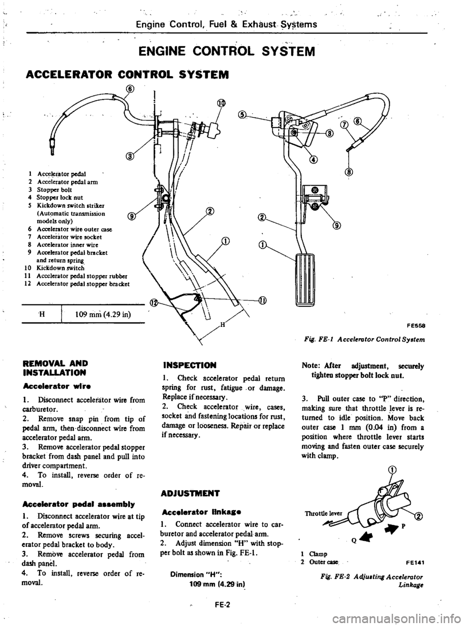
ACCELERATOR
CONTROL
SYSTEM
@
s
1
Acce
i
ator
pedal
2
Accelerator
pedal
arm
3
Stopper
bolt
4
Stopper
lock
nut
S
Kickdown
switch
striker
Automatic
transmission
models
only
6
Accelerator
wire
outer
case
1
Accelerator
wire
socket
8
Accelerator
inner
wire
9
Accelerator
pedal
bracket
and
return
spring
10
Kickdown
switch
11
Accelerator
pedal
stopper
rubber
12
Accelerator
pedal
stopper
bracket
H
109
mm
4
29
in
REMOVAL
AND
INSTALLATION
Accelerator
wI
e
I
Disconnect
accelerator
wire
from
carburetor
2
Remove
snap
pin
from
tip
of
pedal
arm
then
disconnect
wire
from
accelerator
pedal
arm
3
Remove
accelerator
pedal
stopper
bracket
from
dash
panel
and
pull
into
driver
compartment
4
To
install
reverse
order
of
Ie
moval
Accelerator
pedal
a
embly
I
Disconnect
accelerator
wire
at
tip
of
accelerator
pedal
arm
2
Remove
screws
securing
accel
erator
pedal
bracket
to
body
3
Remove
accelerator
pedal
from
dash
panel
4
To
install
reverse
order
of
re
moval
I
IJ
1
II
I
V
J
v
I
@
INSPECTION
I
Check
accelerator
pedal
return
spring
for
rust
fatigue
or
damage
Replace
if
necessary
2
Check
accelerator
wire
cases
socket
and
fastening
locations
for
rust
damage
or
looseness
Repair
or
replace
if
necessary
ADJUSTMENT
Accelerator
IInka
e
I
Connect
accelerator
wire
to
car
buretor
and
accelerator
pedal
arm
2
Adjust
dilnension
H
with
stop
per
bolt
as
shown
in
Fig
FE
I
Dimension
H
109mm
4
29
in
FE
2
F
E558
Fig
FE
I
Accelerator
Control
System
Note
After
adjustment
securely
tighten
stopper
bolt
lock
nut
3
Pull
outer
case
to
uP
direction
making
sure
that
throttle
lever
is
re
turned
to
idle
position
Move
back
outer
case
I
mm
0
04
in
from
a
position
where
throttle
lever
starts
moving
and
fasten
outer
case
securely
with
clamp
Q4t
1
Clamp
2
Outer
case
FE1
1
Fig
FE
2
Adju
ting
Accolerator
Linkage
Page 410 of 548

Enr
in
e
Control
Fuel
l
c
I
xhaust
System
i
SEALING
COMPOuND
If
exhaust
tubes
are
separated
at
connection
to
renew
muffler
assembly
etc
use
the
Genuine
Nissan
Sealant
Exhaust
Sealant
Kit
20720
N2225
to
eliminate
gas
leakage
past
the
joint
Be
sure
to
observe
following
proce
dures
ee
Fig
FJ
r21
I
Wipe
clean
all
the
oontact
por
tions
of
tube
joints
allow
them
to
dry
thoroughly
2
Temporarily
mount
in
place
muf
fler
assembly
and
or
exhaust
tube
as
an
assembled
unit
on
the
car
i
Insert
the
male
tube
into
the
female
tube
fully
until
the
front
end
of
the
female
tube
touches
the
stopper
on
the
male
tube
A
55mm
2
17in
B
t
Smm
0
59i
AI
B
Il
L
l
F
E574
Fig
FE
19
Ex
unut
Tube
Connection
4
Torque
exhaust
tube
clip
securing
bolt
and
exhaust
tube
mounting
bolt
to
specifications
liJ
Tightening
torque
Exhaust
tube
clip
bolt
0
8
to
1
2
kg
m
15
8
to
8
7
h
bl
5
Squeeze
5
to
6
cc
0
31
to
0
37
cu
in
of
sealant
into
injector
from
the
sealant
tube
Be
sure
to
place
the
cap
back
to
the
sealant
tube
since
sealant
will
dry
Sealant
tube
A
5
to
6
cc
0
31
toO
37cuin
FEltl
Fig
FE
20
Squeezing
Senlant
to
Injector
6
Position
the
nozzle
of
injector
to
the
guide
and
press
it
there
firmly
Inject
sealant
slowly
until
sealant
be
gins
to
flow
out
of
the
slit
of
the
tube
This
indicates
that
the
bead
requires
no
further
sealant
Excessive
sealant
can
cause
a
clogged
tube
See
Fig
FE
22
After
injecting
wash
injector
thor
oughly
in
clean
water
to
remove
all
FE
12
FE109
Fig
FE
21
Exhaust
Sealant
Kit
traces
of
sealant
7
Start
the
engine
and
let
it
idle
slowly
for
ten
minutes
minilnum
to
harden
sealant
with
the
heat
of
ex
haust
gas
8
Check
the
oondition
of
sealant
before
driving
the
car
It
is
also
essen
tial
that
the
car
should
not
be
accel
erated
sharply
for
20
to
30
minutes
subsequent
to
this
operation
FE568
Fig
FE
22
Injecting
Seatant
Page 446 of 548
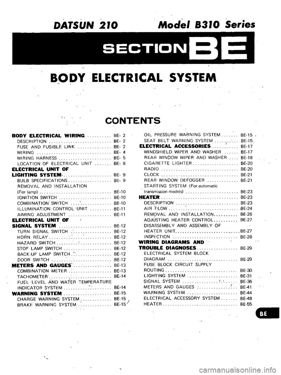
DATSUN
210
Model
8310
Series
SECTIONBE
BODY
ELECTRICAL
SYSTEM
CONTENTS
BODY
ELECTRICAL
WIRING
DESCRIPTION
FUSE
AND
FUSIBLE
LINK
WIRING
WIRING
HARNESS
LOCATION
OF
ELECTRICAL
UNIT
ELECTRICAL
UNIT
OF
LIGHTING
SYSTEM
BULB
SPECIFICATIONS
REMOVAL
AND
INSTALLATION
For
lamp
IGNITION
SWITCH
COMBINATION
SWITCH
ILLUMINATION
CONTROL
UNIT
AIMING
ADJUSTMENT
ELECTRICAL
UNIT
OF
SIGNAL
SYSTEM
BE
12
TURN
SIGNAL
SWITCH
BE
12
HORN
RELAY
BE
12
HAZARD
SWITCH
BE
12
STOP
LAMP
SWITCH
BE
12
BACK
UP
LAMP
SWITCH
BE
12
DOOR
SWITCH
BE
12
METERS
AND
GAUGES
BE
13
COMBINATION
METER
BE
13
TACHOMETER
BE
14
FUEL
LEVEL
AND
WATER
TEMPERATURE
INDICATOR
SYSTEM
BE
14
WARNING
SYSTEM
BE
15
CHARGE
WARNING
SYSTEM
BE
15
BRAKE
WARNING
SYSTEM
BE
15
BE
2
BE
2
BE
2
BE
4
BE
5
BE
8
BE
9
BE
9
BE
10
BE
10
BE
10
BE
11
BE
11
OIL
PRESSURE
WARNING
SYSTEM
SEAT
BELT
WARNING
SYSTEM
ELECTRICAL
ACCESSORIES
WINDSHIELD
WIPER
AND
WASHER
REAR
WINDOW
WIPER
AND
WASHER
CIGARETTE
LIGHTER
RADIO
CLOCK
REAR
WINDOW
DEFOGGER
STARTING
SYSTEM
For
automatic
transmission
models
HEATER
DESCRIPTION
AIR
FLOW
REMOVAL
AND
INSTALLATION
ADJUSTING
HEATER
CONTROL
DISASSEMBLY
AND
ASSEMBLY
OF
HEATER
UNIT
INSPECTION
WIRING
DIAGRAMS
AND
TROUBLE
DIAGNOSES
ELECTRICAL
SYSTEM
BLOCK
DIAGRAM
FUSE
BLOCK
CIRCUIT
SUPPLY
ROUTING
LIGHTING
SYSTEM
SIGNAL
SYSTEM
METERS
AND
GAUGES
WARNING
SYSTEM
ELECTRICAL
ACCESSORY
SYSTEM
HEATER
BE
15
BE
15
BE
17
BE
17
BE
18
BE
20
BE
20
BE
21
BE
21
BE
23
BE
23
BE
23
BE
24
BE
26
BE
27
BE
27
BE
28
BE
29
BE
29
BE
30
BE
31
BE
36
BE
41
BE
44
BE
4B
BE
55