timing belt DATSUN 210 1979 Service Manual
[x] Cancel search | Manufacturer: DATSUN, Model Year: 1979, Model line: 210, Model: DATSUN 210 1979Pages: 548, PDF Size: 28.66 MB
Page 15 of 548
DATSUN
210
Model
8310
Series
SECTIONET
ET
ENGINE
TUNE
UP
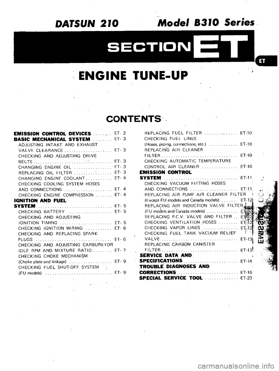
CONTENTS
EMISSION
CONTROL
DEVICES
BASIC
MECHANICAL
SYSTEM
ADJUSTING
INTAKE
AND
EXHAUST
VALVE
CLEARANCE
CHECKING
AND
ADJUSTING
DRIVE
BELTS
CHANGING
ENGINE
OIL
REPLACING
01
L
FI
L
TER
CHANGING
ENGINE
COOLANT
CHECKING
COOLING
SYSTEM
HOSES
AND
CONNECTIONS
CHECKING
ENGINE
COMPRESSION
IGNITION
AND
FUEL
SYSTEM
CHECKING
BATTERY
CHECKING
AND
ADJUSTING
IGNITION
TIMING
CHECKING
IGNITION
WIRING
CHECKING
AND
REPLACING
SPARK
PLUGS
CHECKING
AND
ADJUSTING
CARBURETOR
IDLE
RPM
AND
MIXTURE
RATIO
CHECKING
CHOKE
MECHANISM
Choke
plate
and
linkage
CHECKING
FUEL
SHUT
OFF
SYSTEM
FU
models
ET
2
ET
3
ET
3
ET
3
ET
3
ET
3
ET
4
ET
4
ET
4
ET
5
ET
5
ET
5
ET
6
ET
6
ET
7
ET
9
ET
9
REPLACING
FUEL
FILTER
ET
10
CHECKING
FUEL
LINES
Hoses
piping
connections
etc
ET
10
REPLACING
AIR
CLEANER
FILTER
ETlO
CHECKING
AUTOMATIC
TEMPERATURE
CONTROL
AIR
CLEANER
ET
10
EMISSION
CONTROL
SYSTEM
ET
11
CHECKING
VACUUM
FITTING
HOSES
AND
CONNECTIONS
ET
11
REPLACING
AIR
PUMP
AIR
CLEANER
FILTER
Except
FU
models
and
Canada
models
E
1122i
REPLACING
AIR
INDUCTION
VALVE
FILTER
FU
models
and
Canada
models
E
tlil1r2
C
REPLACING
PCV
VALVE
AND
FILTER
ETf
CHECKING
VENTI
LATION
HOSES
E1P12
CHECKING
VAPOR
LINES
Eli
J2
CHECKING
FUEL
TANK
VACUUM
RELIEF
I
f
III
VALVE
ET
13
REPLACING
CARBON
CANISTER
W
FILTER
ET
d
SERVICE
DATA
AND
SPECIFICATIONS
ET
14
TROUBLE
DIAGNOSES
AND
CORRECTIONS
ET
16
SPECIAL
SERVICE
TOOL
ET
23
Page 30 of 548
Engine
Tune
up
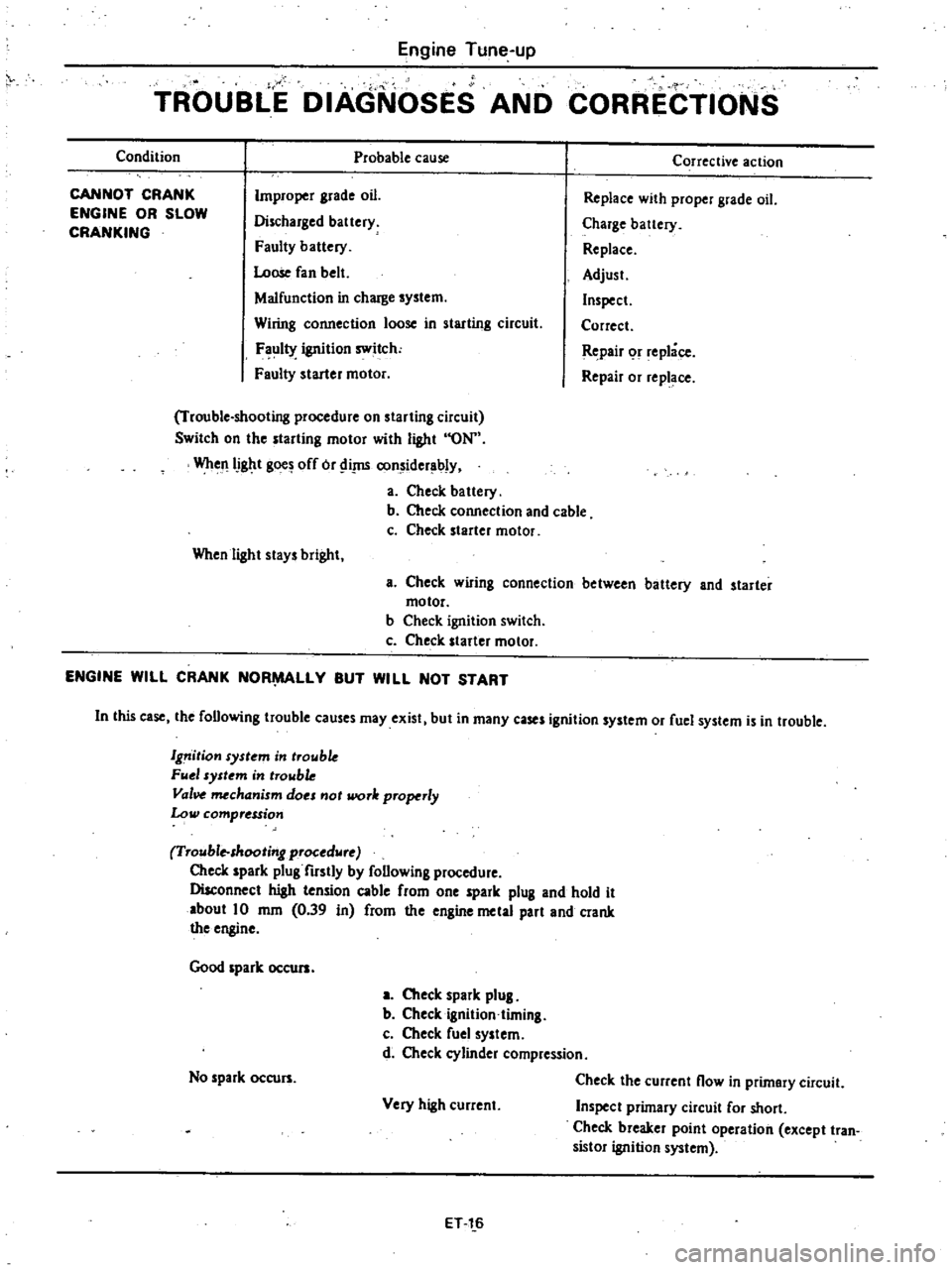
TROUBLE
DIAGNOSES
AND
CORRECTIONS
Condition
Probable
cause
CANNOT
CRANK
ENGINE
OR
SLOW
CRANKING
Improper
grade
oil
Discharged
battery
Faulty
battery
Loose
fan
belt
Malfunction
in
charge
system
Wiring
connection
loose
in
starting
circuit
F
ul1Y
ignition
switch
Faulty
starter
motor
Trouble
shooting
procedure
on
starting
circuit
Switch
on
the
starting
motor
with
light
ON
WheJlIJght
gOO
off
or
Ii
J1S
considerably
a
Check
battery
b
Check
connection
and
cable
c
Check
starter
motor
When
light
stays
bright
Corrective
action
Replace
with
proper
grade
oil
Charge
battery
Replace
Adjust
Inspect
Correct
Repair
or
replace
Repair
or
replace
a
Check
wlflng
connection
between
battery
and
starter
motor
b
Check
ignition
switch
c
Check
starter
motor
ENGINE
WILL
CRANK
NOR
LLY
BUT
WILL
NOT
START
In
this
case
the
following
trouble
causes
may
exist
but
in
many
cases
ignition
system
or
fuel
system
is
in
trouble
19
ition
syst
m
in
trouble
FII
1
system
in
trowb
Val
mechanism
do
not
work
properly
Low
compression
Trouble
shooting
procedure
Check
spark
plug
firstly
by
following
procedure
Disconnect
high
tension
cable
from
one
spark
plug
and
hold
it
about
10
mm
0
39
in
from
the
engine
metal
part
and
crank
the
engine
Good
spark
occurs
a
Check
spark
plug
b
Checkignition
timing
c
Check
fuel
system
d
Check
cylinder
compression
Check
the
current
now
in
primary
circuit
Very
high
current
Inspect
primary
circuit
for
short
Check
breaker
point
operation
except
tran
sistor
ignition
system
No
spark
occurs
ET
l
6
Page 33 of 548
Condition
ENGINE
POWER
NOT
UP
TO
NORMAL
Low
compmsion
Ignition
system
out
of
order
Fuel
system
out
of
order
Air
intake
system
out
of
order
Emission
control
Overheating
J
f
H
r
Overcooling
Engine
liune
up
Probable
cause
Malfunction
of
throttle
valve
switch
and
linkage
FU
models
Incorrect
ignition
timing
Damaged
spark
plugs
Wom
distributor
points
Malfunction
of
T
C
S
cMalfunction
of
S
D
V
Milfunction
of
choke
system
Clogged
fuel
pipe
or
floating
valve
Dirty
or
clogged
fuel
filter
Fuel
pump
will
not
work
properly
Clogged
carb
retor
jets
Clogged
air
cleaner
Air
aling
from
manifold
g
sket
r
carburetor
gasket
Malfunction
of
E
G
R
valve
Stick
E
F
E
valve
shaft
Insufficient
coolant
Loose
fan
bel
Wom
or
oiled
fan
belt
Inoperative
therinostat
Wom
ater
pu
p
Clogged
or
leaky
radiator
Wom
radiator
filler
ca
Air
in
cooling
ystein
Improper
engine
oil
grade
Incorrect
ignition
timing
Clogged
carburetor
lean
miiture
Inoperative
thermostat
1
ET
19
Corrective
action
Check
throttle
valve
switch
and
linkage
Adjusi
i
r
replace
if
necessary
Previously
m
entioned
Adjust
Clean
adjust
or
replace
plugs
Dress
or
replace
points
Also
check
condenser
Check
and
correct
Check
and
replace
Adjust
Clean
Replace
Repair
or
replace
t
J
Disassemble
and
clean
Replace
element
Replace
gasket
Check
and
replace
Repair
Replenish
Adjust
fan
belt
Replace
Replace
Repl
ce
Flush
repair
or
replace
ReplaCe
Retightin
e
ch
part
of
cooling
system
Replace
with
proper
grade
oil
Adjust
Overhaui
carburetor
Replace
Page 80 of 548
DESCRIPTION
The
cooling
system
is
of
the
con
ventional
pressure
type
A
centrifugal
1P
a
COOLANT
LEVEL
Pour
coolant
into
the
radiator
up
to
the
cap
and
also
into
the
reservoir
up
to
the
MAX
level
CAUTION
To
avoid
serious
personal
injury
never
remove
radiator
cap
quickly
when
engine
is
hot
Sudden
release
of
cool
ing
system
pressure
is
very
dangerous
If
it
is
necessary
to
remove
radiator
cap
when
radiator
is
hot
turn
cap
slowly
counterclockwise
to
the
first
step
After
all
pressure
in
the
cool
ing
system
is
released
turn
cap
passing
the
stop
and
remove
it
DRAINING
AND
FLUSHING
THE
COOLING
SYSTEM
To
drain
the
cooling
system
re
move
radiator
cap
release
drain
cock
C09ling
System
COOLING
SYSTEM
pump
installed
on
the
timing
chain
cover
serves
to
circulate
the
coolant
The
pressure
t
pe
radiator
filler
cap
at
the
bottom
of
radiator
and
drain
plug
on
the
left
side
of
cylinder
block
If
the
heater
system
is
instaDed
set
heater
control
valve
to
open
position
Mter
the
coolant
is
drained
complete
ly
close
drain
cock
and
plug
and
refdl
the
system
with
clean
soft
water
WATER
PUMP
The
water
pump
is
of
a
centrifugal
type
which
is
mounted
on
the
engine
front
cover
TJ
te
pump
shaft
is
sup
ported
by
a
double
row
of
baD
bear
ings
press
fit
in
an
aluminum
die
cast
pump
body
The
bearings
are
per
manently
lubricated
and
sealed
to
pre
vent
loss
of
lubricant
and
entry
of
dirt
CO
2
installed
on
the
radiator
operates
the
cooling
system
at
higher
than
atmos
pheric
pressure
To
heater
From
heater
C0126
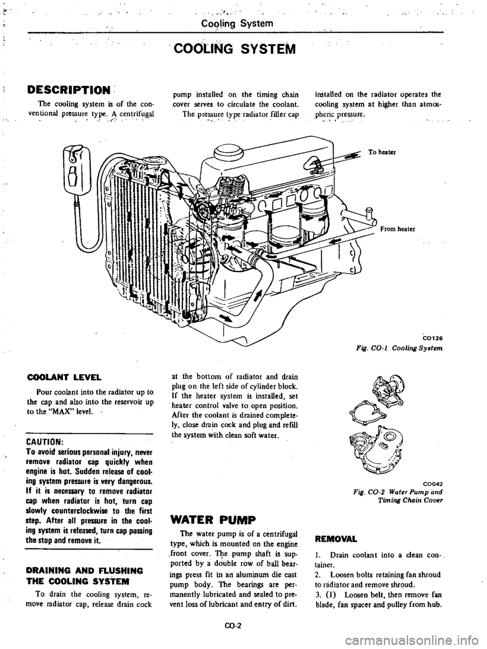
Fig
COol
Cooling
System
C0042
Fig
CO
2
Water
Pump
and
Timing
Chain
Couer
REMOVAL
1
Drain
coolant
into
a
clean
con
tainer
2
Loosen
bolts
retaining
fan
shroud
to
radiator
and
remove
shroud
3
I
Loosen
belt
then
remove
fan
blade
fan
spacer
and
pulley
from
hub
Page 85 of 548
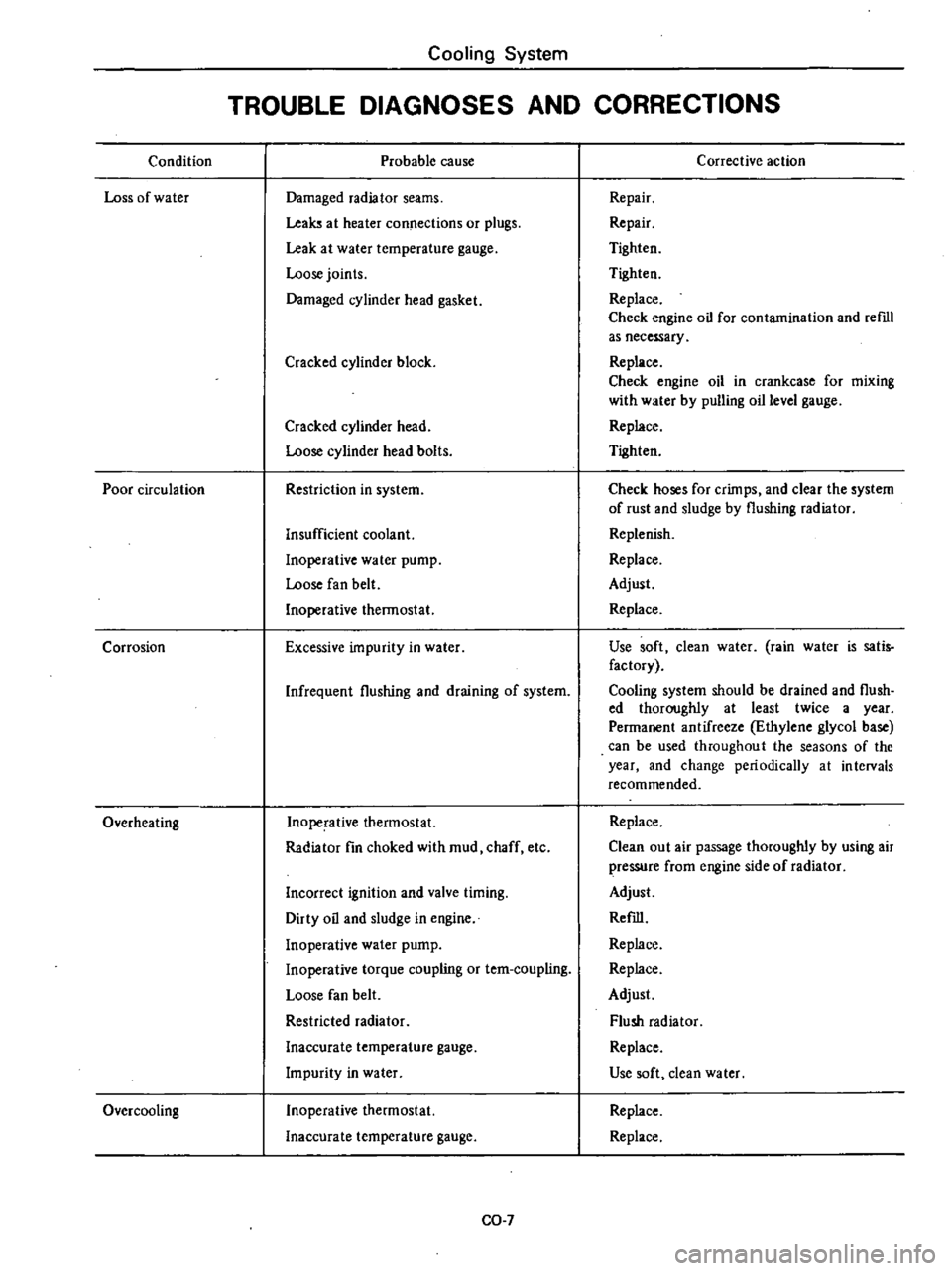
Condition
Loss
of
water
Poor
circulation
Corrosion
Overheating
Over
cooling
Cooling
System
TROUBLE
DIAGNOSES
AND
CORRECTIONS
Probable
cause
Damaged
radiator
seams
Leaks
at
heater
connections
or
plugs
Leak
at
water
temperature
gauge
Loose
joints
Damaged
cylinder
head
gasket
Cracked
cylinder
block
Cracked
cylinder
head
Loose
cylinder
head
bolts
Restriction
in
system
Insufficient
coolant
Inoperative
water
pump
Loose
fan
belt
Inoperative
thermostat
Excessive
impurity
in
water
Infrequent
flushing
and
draining
of
system
Inoperative
thermostat
Radiator
fin
choked
with
mud
chaff
etc
Incorrect
ignition
and
valve
timing
Dirty
oil
and
sludge
in
engine
Inoperative
water
pump
Inoperative
torque
coupling
or
tem
coupling
Loose
fan
belt
Restricted
radiator
Inaccurate
temperature
gauge
Impurity
in
water
Inoperative
thermostat
Inaccurate
temperature
gauge
CO
7
Corrective
action
Repair
Repair
Tighten
Tighten
Replace
Check
engine
oil
for
contamination
and
reml
as
necessary
Replace
Check
engine
oil
in
crankcase
for
mixing
with
water
by
pulling
oil
level
gauge
Replace
Tighten
Check
hoses
for
crimps
and
clear
the
system
of
rust
and
sludge
by
flushing
radiator
Replenish
Replace
Adjust
Replace
Use
soft
clean
water
rain
water
is
satis
factory
Cooling
system
should
be
drained
and
flush
ed
thoroughly
at
least
twice
a
year
Permanent
antifreeze
Ethylene
glycol
base
can
be
used
throughout
the
seasons
of
the
year
and
change
periodically
at
intervals
recommended
Replace
Clean
out
air
passage
thoroughly
by
using
air
pressure
from
engine
side
of
radiator
Adjust
Refill
Replace
Replace
Adjust
Flush
radiator
Replace
Use
soft
dean
water
Replace
Replace