differential DATSUN 210 1979 Service Manual
[x] Cancel search | Manufacturer: DATSUN, Model Year: 1979, Model line: 210, Model: DATSUN 210 1979Pages: 548, PDF Size: 28.66 MB
Page 6 of 548
f
Destination
u
s
A
t
f
l
c
J
r
If
i
i
c
1J
ll
d
Canada
I
C
f
Sedan
Hatchba
k
Wagon
Sedan
HatChback
Wagon
Sedan
Hatchback
Wagon
Class
4
door
2
do
or
I
4
door
2
door
4
door
2
door
General
Inform
ation
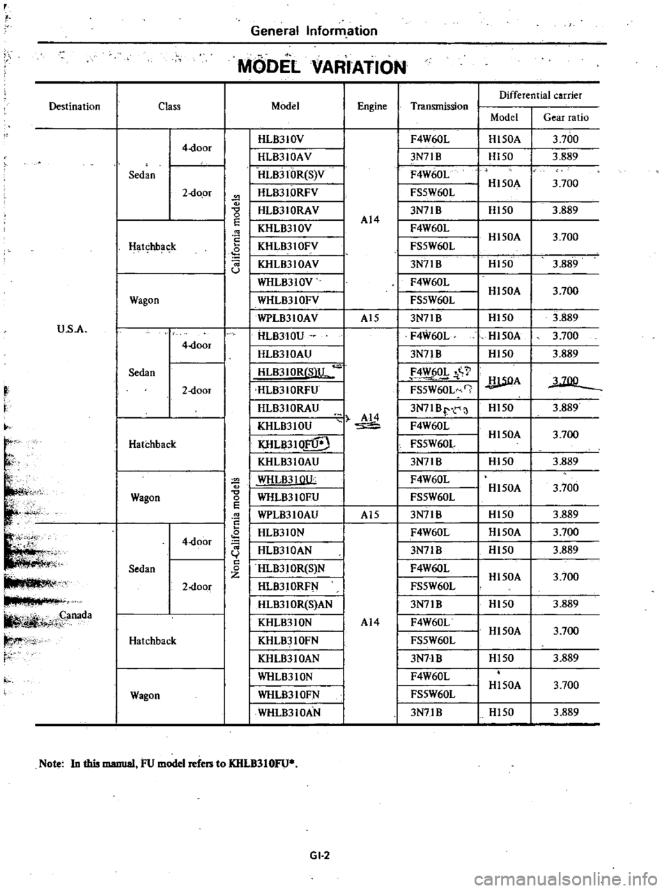
MODEL
VARIATION
Model
Engine
I
HL8310V
I
HLB310AV
IHLB3IOR
S
V
I
HLB310RFV
I
i
I
HLB310RAV
I
KHLB310V
I
KHLB310FV
J
I
KHLB310AV
I
WHLB310V
I
WHLB310FY
WPLB310AV
HLB310U
I
HLB310AU
I
HLB3IOR
S
lL
IHLB310RFU
I
HLB310RAU
AI4
I
KHLB310U
I
KHLB310FU
O
I
KHLB310AU
I
WHLB3
WU
g
WHLB310FU
E
WPLB310AU
HLB310N
HLB310AN
c
HLB310R
S
N
HLB310RF
I
HLB3IOR
S
AN
KHLB310N
KHLB310FN
KHLB310AN
WHL83
ION
WHLB310FN
WHLB310AN
Note
In
this
manual
FU
model
refers
to
KHLB310FU
GI
2
I
I
I
Transmission
AI4
F4W60L
I
3N7lB
I
F4W60L
I
FS5W60L
I
3N71B
I
F4W60L
J
FS5W60L
I
3N71B
I
F4W60L
FS5W60L
3N71B
I
F4W60L
I
3N71
B
I
4
Y
6Q
I
FS5W60L
J
I
3N7IBr
I
F4W60L
I
FS5W60L
3N71B
F4W60L
FS5W60L
3N7IB
F4W60L
3N71B
F4W60L
FS5W60L
3N71B
F4W60L
FS5W60L
I
3N71B
I
F4W60L
I
FS5W60L
I
3N7lB
AI5
AI5
AI4
Differential
carrier
Model
Gear
ratio
Hl50A
H150
Hl50A
Hl50
HI50A
H150
Hl50A
Hl50
HI50A
Hl50
UOA
Hl50
Hl50A
HI50
HI50A
HI50
HI50A
HI50
H150A
HI50
HI50A
Hl50
Hl50A
Hl50
3
700
3
889
3
700
3
889
3
700
3
889
3
700
3
889
3
700
3
889
3
700
I
3
889
3
700
3
889
3
700
3
889
3
700
3
889
3
700
3
889
3
700
3
889
3
700
3
889
Page 9 of 548
Erigine
crankcase
EI
gine
cooling
system
Transmission
case
Final
drive
case
housing
Steering
gear
box
Fuel
tank
Air
conditioning
system
Refrigerant
Compressor
oil
f
tl
It
J
4
i
1
protect
the
catalytic
cop
verter
froitr
contamination
t
n
General
Information
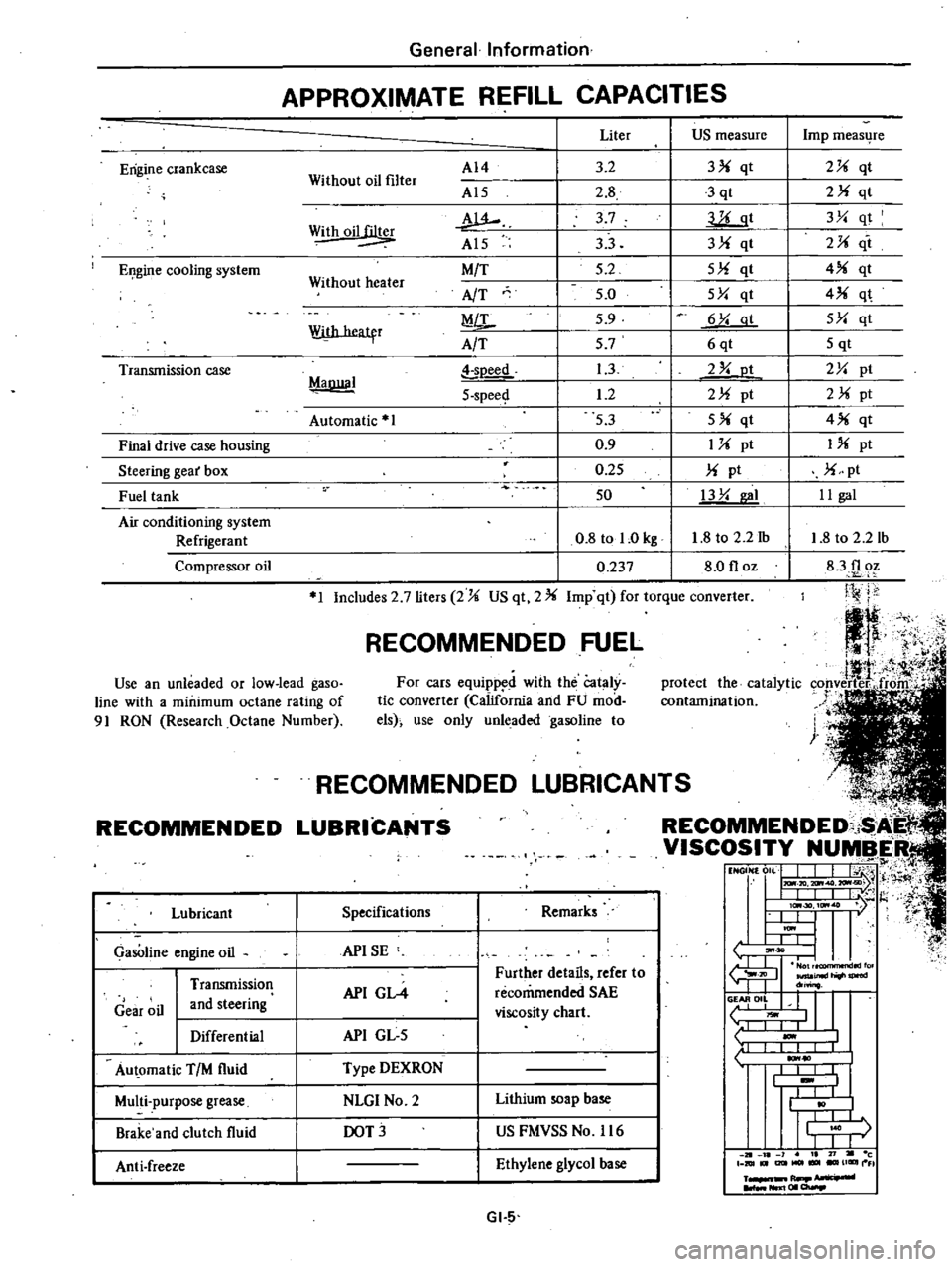
APPROXIMATE
REFILL
CAPACITIES
Without
oil
filter
AI4
Al5
w
Al5
M
T
AfT
MiL
A
T
Liter
US
measure
3
2
3
qt
2
8
3
qt
3
7
llLgt
33
3
qt
5
2
5
qt
5
0
5Y
qt
5
9
6
Y
at
57
6qt
1
3
2
Y
ot
1
2
2
pt
53
5
qt
0
9
1
pt
0
25
pt
50
13
Y
I
0
8
tol
Okg
1
8
to
2
2
1b
0
237
8
0
floz
Withoil
Without
heater
With
heatfr
MaDllal
soeed
5
spee
Automatic
1
1
Includes
2
7
liters
2
US
qt
2
Imp
qt
for
torque
converter
RECOMMENDED
FUEL
Use
an
unleaded
or
low
lead
gaso
line
with
a
minimum
octane
rating
of
91
RON
Research
Octane
Number
For
cars
equipp
d
with
the
Cataly
tic
converter
California
and
FU
mod
els
use
only
unleaded
gasoline
to
RECOMMENDED
Lubricant
GasOline
engine
oil
Gear
oil
Transmission
and
steering
Differential
Au
omatic
TIM
fluid
Multi
purpose
grease
Brake
and
clutch
fluid
Anti
freeze
L
NDED
LUBRICAN
COMMENDED
i
I
VISCOSITY
NUMBER
t1
NGON
0
L
J
I
j
H
I
IlL
I
t
l
I
lc
30
ItM
7
l
t
U
I
ItM
I
L
L
tJ
30
I
I
fu
JIl
inld
do
o
II
L
liOwl
1
I
I
1
10
I
I
I
I
t
I
I
j
r
I
I
J
1
21
l
1
I
71
c
DIUt
I2lItMOl
UGIIII
FI
R
NIl
I
01
a
Specifications
Remarks
APISE
API
GL4
Further
details
refer
to
recommended
SAE
viscosity
chart
API
GL
5
Type
DEXRON
NLGI
No
2
Lithium
soap
base
DOT
US
FMVSS
No
116
Ethylene
glycol
base
GI
5
Imp
meas4re
2
qt
2
qt
3Y
qt
2
it
4
qt
4
q
5Y
qt
5
qt
2Y
pt
2
pt
4
qt
I
pt
pt
II
gal
1
8
to
2
2
lb
83f1
oz
Ji
j
j
Page 12 of 548
MAiNTENANCE
OPERATION
Periodic
maintenance
should
be
performed
at
number
of
kilometers
mila
or
month
whichewr
comes
first
Kilometers
1
000
Mile
x
1
000
M
3nthl
MAINTENANCE
INTERVAL
1
6
I
12
I
24
I
36
I
48
I
60
72
111
117
611
11511122
511
30
1137
5
45
I
6
I
12
r
16
I
24
I
30
36
UNDERHOOD
MAINTENANCE
Gl
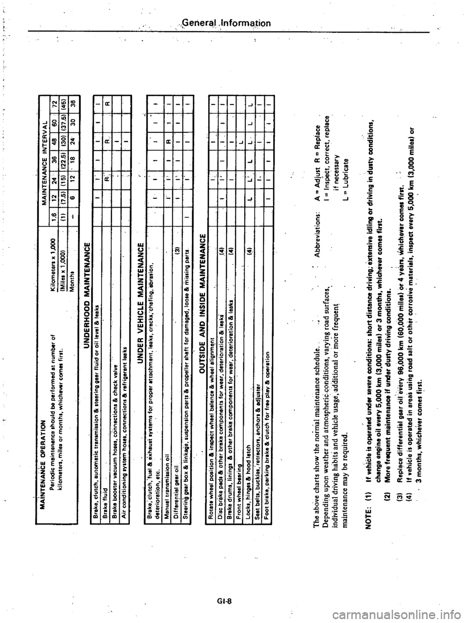
The
above
charts
show
the
normal
maintenance
schedule
Dependir
tg
upon
weather
and
atmospheric
conditions
varying
road
surfaces
individual
driving
habits
and
vehicle
usage
additionai
or
more
frequen
maintenance
may
be
required
Abbreviations
A
Adjust
R
Replace
I
Inspe
t
correct
replace
if
necessary
L
Lubricate
NOTE
1
If
vehicle
i
operated
under
evere
conditions
hort
distance
driving
extensive
idling
or
driving
in
du
ty
condition
change
angine
oil
every
5
000
km
3
000
mile
or
3
month
whlchevar
come
first
2
More
frequent
maintenance
if
under
dusty
driving
condition
3
Replace
differential
gear
oile
ery
96
000
km
60
000
mila
or
4
years
whichaver
com
first
4
If
vehicle
i
operated
in
ereas
u
ing
road
alt
or
other
corro
ive
material
inspect
evary
5
000
km
3
000
mile
or
3
months
whichever
comes
first
Page 13 of 548
General
Information
LIFTING
POINTS
AND
TOWING
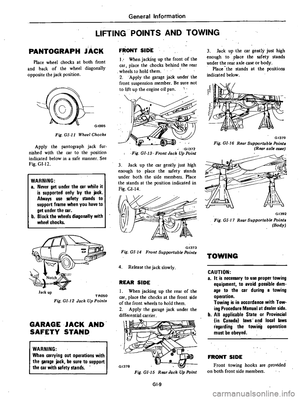
PANTOGRAPH
JACK
Place
wheel
chocks
at
both
front
and
back
of
the
wheel
diagonally
opposite
the
jack
position
GIOB5
Fig
GI
I
I
Wheel
Chocks
Apply
the
pantograph
jack
fur
nished
with
the
car
to
the
position
indicated
below
in
a
safe
manner
See
Fig
GI
12
WARNING
a
Never
get
under
the
car
while
it
is
supported
only
by
the
jack
Always
use
safety
stands
to
support
frame
when
you
have
to
get
under
the
car
b
Block
the
wheels
diagonally
with
wheel
chocks
Jack
up
TROSO
Fig
GI
12
Jack
Up
Points
GARAGE
JACK
AND
SAFETY
STAND
WARNING
When
carrying
out
operations
with
the
garage
jack
be
sure
to
support
the
car
with
safety
stands
FRONT
SID
E
I
When
jacking
up
the
front
of
the
car
place
the
chocks
behind
the
rear
wheels
to
hold
them
2
Apply
the
garage
jack
under
the
front
suspension
member
Be
sure
not
to
lift
up
the
engine
oil
pan
GI372
Fig
GI
13
Front
Jack
Up
Point
3
Jack
up
the
car
gently
just
high
enough
to
place
the
safety
stands
under
both
the
side
members
Place
the
stands
at
the
position
indicated
in
Fig
GI
14
GI373
Fig
GI
14
Front
Supportable
Point
4
Release
the
jack
slowly
REAR
SIDE
When
jacking
up
the
rear
of
the
car
place
the
chocks
at
the
front
side
of
the
front
wheels
to
hold
them
2
Apply
the
garage
jack
under
the
differential
carrier
1
1
Il
GI378
Fig
GI
15
Rear
Jack
Up
Point
GI
9
3
Jack
up
the
car
gently
just
high
enough
to
place
the
safety
stands
under
the
rear
axle
case
or
body
Place
the
stands
at
the
positions
indicated
below
GI379
Fig
GI
16
Rear
Supportable
Point
Rear
axle
c
rue
GI392
Fig
01
17
Rear
Supportable
Point
Body
TOWING
CAUTION
a
It
is
necemry
to
use
proper
towing
equipment
to
avoid
possible
dam
age
to
the
car
during
a
towing
operation
Towing
is
in
accordance
with
Tow
ing
Procedure
Manual
at
dealer
side
b
All
applicable
State
or
Provincial
in
Canada
laws
and
local
laws
regarding
the
towiilg
operation
must
be
obeyed
FRONT
SIDE
Front
towing
hooks
are
provided
on
both
front
side
members
Page 63 of 548

CYLINDER
BLocK
t
60
2
36
20
0
79
I
100
CI
94
rJ
L
II
E9
I
Unit
mm
in
EM479
Cylinder
liner
for
service
4
0
0
157
Undersize
4
5
0
177
Undersize
Engine
MechanicliIl
Surface
flatness
Inner
diameter
Cylinder
bore
Out
of
round
X
V
Taper
A
B
Differential
in
inner
diameter
between
cylinders
Piston
to
cylinder
block
clearance
Outside
diameter
80
00
to
80
05
3
1496
to
3
1515
80
50
to
80
55
3
1692
to
3
1712
PISTON
PISTON
RING
AND
PISTON
PIN
Piston
e
e
5
51
co
ED
I
H
EM4S0
Standard
Over
size
0
50
0
0197
1
00
0
0394
EM
26
Standard
Less
than
0
05
0
0020
76
000
to
76
050
2
9921
to
2
994i
Less
than
O
oI5
0
0006
Less
than
O
oI5
0
0006
Less
than
0
05
0
OO20
0
025
to
0
045
0
0010
to
0
0018
Unit
riun
in
Inside
diameter
75
50
to
75
60
2
9724
to
2
9763
Piston
diameter
Unit
mm
in
Wear
limit
0
1
0
0039
0
20
0
0079
0
20
0
0079
Unit
mm
in
75
967
to
76
017
2
9908
to
2
9927
76
467
to
76
517
3
0105
to
3
0124
76
967
to
77
017
3
0301
to
3
0321
Page 168 of 548
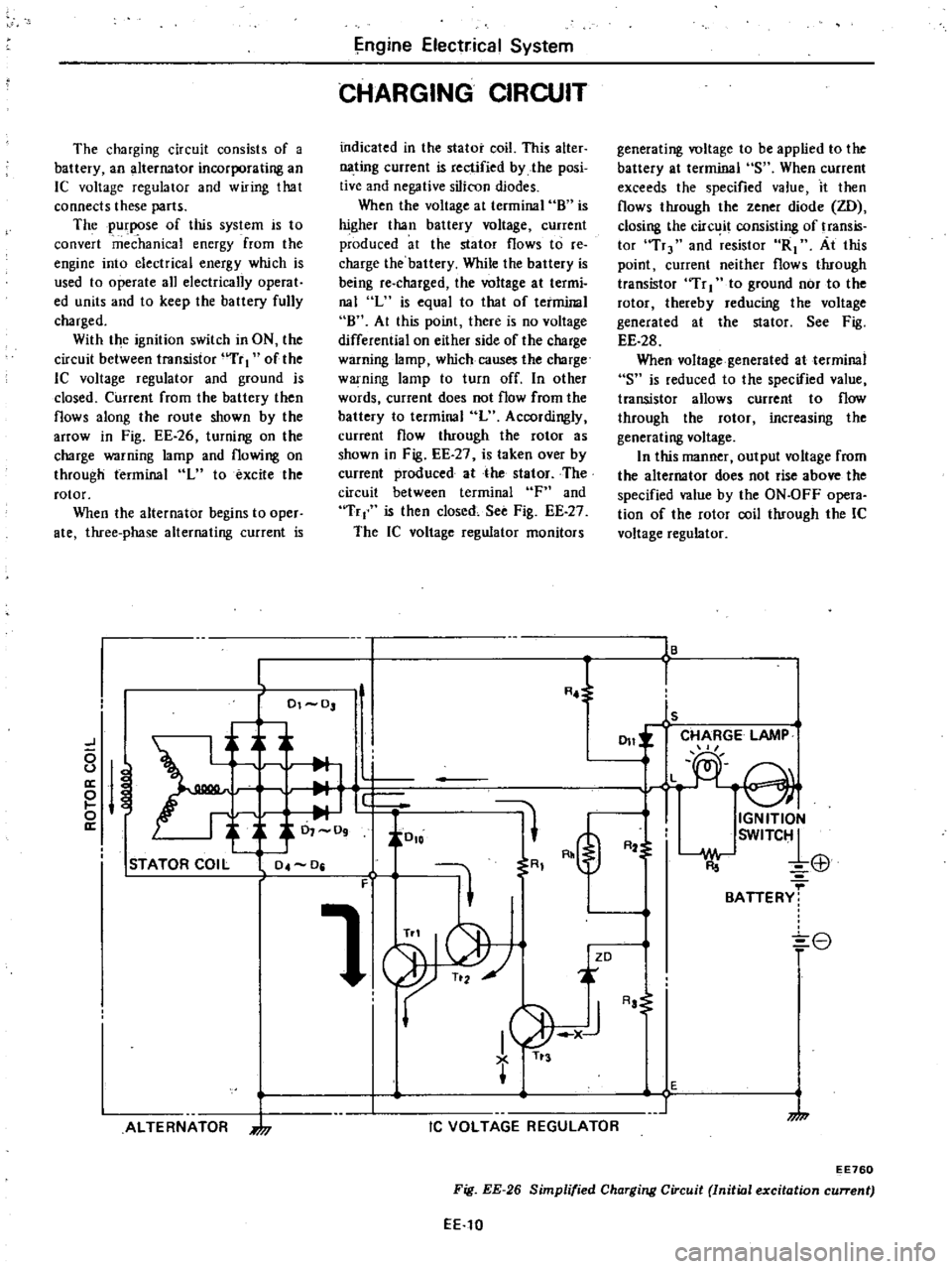
The
charging
circuit
consists
of
a
battery
an
alternator
incorporating
an
IC
voltage
regulator
and
wiring
that
connects
these
parts
The
purpose
of
this
system
is
to
convert
mec
hanka
energy
from
the
engine
into
electrical
energy
which
is
used
to
operate
all
electrically
operat
ed
units
and
to
keep
the
battery
fully
charged
With
the
ignition
switch
in
ON
the
circuit
between
transistor
uTr
I
of
the
lC
voltage
regulator
and
ground
is
closed
Current
from
the
battery
then
flows
along
the
route
shown
by
the
arrOW
in
Fig
EE
26
turning
on
the
charge
warning
lamp
and
flowing
on
through
terminal
L
to
excite
the
rotor
When
the
alternator
begins
to
oper
ate
three
phase
alternating
current
is
ngine
Elect
ical
System
CHARGING
CIRCUIT
indicated
in
the
stator
coil
This
alter
nating
current
is
rectified
by
the
posi
tive
and
negative
silicon
diodes
When
the
voltage
at
terminal
8
is
higher
than
battery
voltage
current
produced
at
the
stator
flows
to
re
charge
the
battery
While
the
battery
is
being
re
charged
the
voltage
at
termi
nal
L
is
equal
to
that
of
terminal
8
At
this
point
there
is
no
voltage
differential
on
either
side
of
the
charge
warning
lamp
which
causes
the
charge
warning
lamp
to
turn
off
In
other
words
current
does
not
flow
from
the
battery
to
terminal
L
Accordingly
current
flow
through
the
rotor
as
shown
in
Fig
EE
27
is
taken
over
by
current
produced
at
the
stator
The
circuit
between
terminal
F
and
Tr
is
then
closed
See
Fig
EE
27
The
IC
voltage
regulator
monitors
generating
voltage
to
be
applied
to
the
battery
at
terminal
S
When
current
exceeds
the
specified
value
it
then
flows
through
the
zener
diode
ZD
closing
the
circ
it
consisting
of
transis
tor
Tr
and
resistor
R1
At
this
point
current
neither
flows
through
transistor
Tr
I
to
ground
nor
to
the
rotor
thereby
reducing
the
voltage
generated
at
the
stator
See
Fig
EE
28
When
voltage
generated
at
terminal
S
is
reduced
to
the
specified
value
transistor
allows
current
to
flow
through
the
rotor
increasing
the
generating
voltage
In
this
manner
output
voltage
from
the
alternator
does
not
rise
above
the
specified
value
by
the
ON
OFF
opera
tion
of
the
rotor
coil
through
the
IC
voltage
regulator
16
L
R
l
I
01
0
ls
CHARGE
LAMP
J
011
L
e
0
u
a
M
e
i
J
0
io
o
IGNITION
a
0
09
SWITC1
R2
El1
STATOR
COIL
04
0
R
F
1
BATTERY
8
ZD
ALTERNATOR
7
I
1
AJ
TI
3
IC
VOLTAGE
REGULATOR
Aa
E
1
7
EE760
Fig
EE
26
Simplified
Charging
Circuit
Initial
excitation
current
EE
10
Page 249 of 548

TIGHTENING
TORQUE
Ball
pin
Striking
lever
lock
nut
S
llft
arm
bracket
Mainshaft
bearing
retainer
screw
Mainshaft
lock
nut
Rear
extension
installation
bolt
Stopper
pin
bolt
Front
cover
installation
bolt
Speedometer
sleeve
lock
ing
plate
bolt
Top
detecting
switch
Reverse
lamp
switch
Neutral
switch
Return
spring
plug
Gear
oil
filler
plug
Gear
oil
drain
plug
Transmission
to
engine
installation
bolt
Tr
msmissiori
to
engihe
rear
plate
installation
bolt
Transmission
to
gusset
installation
bolt
Starting
motor
to
trans
inissi
n
installation
bolt
Rear
mounting
insulator
to
transmission
installation
bolt
Crossmember
mounting
bolt
Rear
engine
mount
installation
bolt
Clutch
operating
cylinder
installation
bolt
Propeller
shaft
to
differential
carrier
Control
lever
pin
installation
nut
Exhaust
mounting
bracket
to
exhaust
front
tube
FU
model
only
Manual
Transmission
F4W60L
2
0
to
3
0
14
to
22
0
9
to
1
2
6
5
to
8
7
0
7
to
1
0
5
1
to
7
2
1
6
to
2
2
12
to
16
0
5
to
0
8
3
6
to
5
8
1
0
to
1
6
7
to
12
0
3
to
0
5
2
2
to
3
6
2
0
to
3
5
14
to
25
2
0
to
3
5
14
to
25
0
5
to
1
0
3
6
to
7
2
2
5
to
4
0
18
to
29
2
5
to
4
0
18
to
29
1
6
to
2
2
12Jo
16
1
6
to
2
2
12
t
16
4
6
to
6
1
33
to
44
3
0
to
4
0
22
to
29
0
9
to
1
2
6
5
to
8
7
3
2
to
4
3
23
to
31
0
9
to
1
2
6
5
to
8
7
3
1
to
4
1
22
to
30
2
4
to
3
3
17
to
24
1
3
to
1
7
9
to
12
3
2
to
4
3
23
to
31
MT33
Unit
kg
m
ft
lb
FS5W60L
2
0
to
3
0
14
to
22
0
9
to
1
2
6
5
to
8
7
8
2
to
10
0
59
to
72
0
8
to
1
3
5
8
to
9
4
10
0
to
11
0
72
to
80
1
6
to
2
2
12
to
16
1
0
to
1
6
7
to
12
0
3
to
0
5
2
2
to
3
6
2
0
to
3
5
14
to
25
2
0
to
3
5
14
to
25
2
0
to
3
5
14
to
25
0
5
to
1
0
3
6
to
7
2
2
5
to
4
0
18
to
29
i
5
to
4
0
18
to
29
1
6
to
2
2
12
to
16
1
6
to
2
2
12
to
16
4
6
to
6
1
33
to
44
3
0
to
4
0
22
to
29
0
9
to
1
2
6
5
to
8
7
3
2
to
4
3
23
to
31
0
9
to
1
2
6
5
to
8
7
3
1
to
4
1
22
to
30
2
4
to
3
3
17
to
24
1
3
to
1
7
9
to
12
3
2
to
4
3
23
to
31
Page 307 of 548

DATSUN
2JO
Model
83
J
0
Series
SECTIONPD
PROPELLER
SHAFT
DIFFERENTIAL
CARRIER
CONTENTS
PROPELLER
SHAFT
INSPECTION
GENERAL
INSPECTION
PROPEllER
SHAFT
VIBRATION
REMOVAL
AND
INSTAllATION
REMOVAL
INSTAllATION
DIFFERENTIAL
CARRIER
REMOVAL
PRE
DISASSEMBl
Y
INSPECTION
DISASSEMBLY
FINAL
DRIVE
ASSEMBLY
DIFFERENTIAL
CASE
INSPECTION
ASSEMBl
Y
AND
ADJUSTMENT
PRECAUTIONS
IN
REASSEMBLY
ASSEMBLY
OF
DIFFERENTIAL
CASE
ADJUSTMENT
OF
DRIVE
PINION
HEIGHT
ADJUSTMENT
OF
DRIVE
PINION
PRELOAD
PD
2
PD
2
PD
2
PD
2
PD
2
PD
2
PD
2
PD
3
PD
3
PD
3
PD
4
PD
4
PD
4
PD
4
PD
5
PD
5
PD
5
PD
6
PD
6
AQJUSTMENT
OF
SIDE
BEARING
SHIMS
INSTAllATION
REPLACEMENT
OF
FRONT
Oil
SEAL
SERVICE
DATA
AND
SPECIFICATIONS
PROPEllER
SHAFT
GENERAL
SPECIFICATIONS
SERVICE
DATA
TIGHTENING
TORQUE
DIFFERENTIAL
CARRIER
GENERAL
SPECIFICATIONS
SERVICE
DATA
TIGHTENING
TORQUE
TROUBLE
DIAGNOSES
AND
CORRECTIONS
PROPEllER
SHAFT
DIFFERENTIAL
CARRIER
SPECIAL
SERVICE
TOOLS
PD
7
PD
9
PD
9
PD
lO
PD
lO
PD
lO
PD
lO
PD
lO
PD
l0
PD
lO
PD
ll
PD
ll
PD
12
PD
12
PD
13
PD
15
Page 308 of 548

Rropeller
Shaft
Differential
Carrier
PROPELLER
SHAFT
INSPECTION
GENERAL
INSPECTION
I
Check
propeller
shaft
tube
sur
Cace
for
dents
or
cracks
If
damaged
replace
with
an
assembly
2
Check
journal
for
axial
play
If
there
is
play
replace
propeller
shaft
mbly
Note
JournaI
cannot
be
disassem
bled
PROPELLER
SHAFT
VIBRATION
To
check
and
correct
an
unbal
anced
propeller
shaCt
proceed
as
Col
lows
L
Remove
undercoating
and
other
foreign
material
which
could
upset
shaft
balance
and
check
shaft
vibra
tion
by
road
test
2
If
shaft
vibration
is
noted
during
road
test
disconnect
propeller
shaft
et
differential
carrier
companion
flange
rotate
companion
flange
180
degrees
and
reinstall
propeller
shaft
ff
3
Again
check
shaft
vibration
If
vibration
still
persists
replace
propel
ler
shaft
assembly
REMOVAL
AND
INSTALLATION
REMOVAL
I
Raise
car
on
hoist
Put
match
malks
both
on
propeller
shaft
and
companion
flange
so
that
shaft
can
be
reinstalled
in
its
original
position
2
Remove
bolts
connecting
pro
peller
shaft
to
companion
flange
PD459
Fig
PD
2
Removing
Propeller
Shaft
PD
2
Tightening
torque
kg
m
ft
b
@
2
410
3
3
1710
24
PD468
Fig
PD
l
PropellerSha
t
3
Draw
out
propeller
shall
sleeve
yoke
from
transmission
by
moving
shaft
realWard
passing
it
under
rear
axle
Plug
up
rear
end
of
rear
extension
housing
to
prevent
oil
leakage
Note
Remove
propeller
aheCt
care
Cully
so
as
not
to
demege
spline
sleeve
yoke
and
rear
oil
seal
INSTALLAnON
To
inS
aJI
reverse
the
foregoing
removal
prOCedure
CAUTION
Align
propeller
shift
with
com
penion
fllnge
of
differentiel
Clrrier
ulling
reference
marks
prl
1Cribed
in
Remova
procedure
and
tightsn
them
with
bolts
Failure
to
do
so
could
resuh
in
driving
vibration
fJ
Tightening
tOlquo
Propellol
sheft
to
companion
f1enge
bolts
2
4
to
3
3
kg
m
117
to
24
ft
b
Page 309 of 548
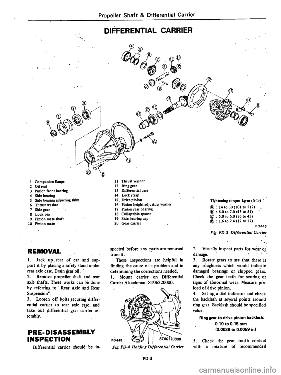
Propeller
Shaft
Differential
Carrier
DIFFERENTIAL
CARRIER
fQ
@
1
11
Thrust
washer
12
Ring
gear
13
Differential
case
14
Lock
strap
15
Drive
pinion
16
Pinion
height
adjusting
washer
17
Pinion
rear
bearing
18
Collapsible
spacer
19
Side
bearing
cap
20
Gear
carrier
1
Companion
flange
2
Oil
seal
3
Pinion
front
bearing
4
Sidebearing
5
Side
bearing
adjusting
shim
6
Thrust
walher
1
Side
gear
8
Lock
pin
9
Pinion
mate
shaft
10
Pinion
mate
Tightening
torque
kg
rn
ft
lb
@
14
to
30
101
to
211
@
6
0101
0
43
to
51
@
5
0
to
5
0
36
to
43
@
1
6
to
2
4
12
to
11
PD446
Fig
PD
3
Differential
Carrier
2
Visuany
inspect
parts
for
wear
of
damage
3
Rotate
gears
to
see
that
there
is
any
roughness
which
would
indicate
damaged
bearings
or
chipped
gears
Check
the
gear
teeth
for
scoring
or
signs
of
abnonnal
wear
Measure
pre
load
of
drive
pinion
4
Set
up
a
dial
indicator
and
check
the
backlash
at
several
points
around
ring
gear
Backlash
should
be
specified
value
Ring
gear
to
drive
pinion
backlash
0
10
to
0
15
mm
0
0039
to
0
0059
inl
spected
before
any
parts
are
removed
from
it
These
inspections
are
helpful
in
fmding
the
cause
of
a
problem
and
in
detennining
the
corrections
needed
Mount
carrier
on
Differential
Carrier
Attachment
ST06320000
REMOVAL
I
Jack
up
rear
of
car
and
sup
port
it
by
placing
a
safety
stand
under
rear
axle
case
Drain
gear
oil
2
Remove
propener
shaft
and
rear
axle
shafts
These
works
can
be
done
by
referring
to
Rear
Axle
and
Rear
Suspensionu
3
Loosen
off
bolts
securing
differ
ell
tial
carrier
to
rear
axle
ca
se
and
take
out
differential
gear
carrier
as
sembly
PRE
DISASSEMBI
Y
INSPE
CTION
Differential
carrier
should
be
in
5
Check
the
gear
tooth
contact
with
a
mixture
of
recommended
Fig
PD
4
Holding
Differential
Carrier
PD
3