turn signal bulb DATSUN 210 1979 Service Manual
[x] Cancel search | Manufacturer: DATSUN, Model Year: 1979, Model line: 210, Model: DATSUN 210 1979Pages: 548, PDF Size: 28.66 MB
Page 446 of 548

DATSUN
210
Model
8310
Series
SECTIONBE
BODY
ELECTRICAL
SYSTEM
CONTENTS
BODY
ELECTRICAL
WIRING
DESCRIPTION
FUSE
AND
FUSIBLE
LINK
WIRING
WIRING
HARNESS
LOCATION
OF
ELECTRICAL
UNIT
ELECTRICAL
UNIT
OF
LIGHTING
SYSTEM
BULB
SPECIFICATIONS
REMOVAL
AND
INSTALLATION
For
lamp
IGNITION
SWITCH
COMBINATION
SWITCH
ILLUMINATION
CONTROL
UNIT
AIMING
ADJUSTMENT
ELECTRICAL
UNIT
OF
SIGNAL
SYSTEM
BE
12
TURN
SIGNAL
SWITCH
BE
12
HORN
RELAY
BE
12
HAZARD
SWITCH
BE
12
STOP
LAMP
SWITCH
BE
12
BACK
UP
LAMP
SWITCH
BE
12
DOOR
SWITCH
BE
12
METERS
AND
GAUGES
BE
13
COMBINATION
METER
BE
13
TACHOMETER
BE
14
FUEL
LEVEL
AND
WATER
TEMPERATURE
INDICATOR
SYSTEM
BE
14
WARNING
SYSTEM
BE
15
CHARGE
WARNING
SYSTEM
BE
15
BRAKE
WARNING
SYSTEM
BE
15
BE
2
BE
2
BE
2
BE
4
BE
5
BE
8
BE
9
BE
9
BE
10
BE
10
BE
10
BE
11
BE
11
OIL
PRESSURE
WARNING
SYSTEM
SEAT
BELT
WARNING
SYSTEM
ELECTRICAL
ACCESSORIES
WINDSHIELD
WIPER
AND
WASHER
REAR
WINDOW
WIPER
AND
WASHER
CIGARETTE
LIGHTER
RADIO
CLOCK
REAR
WINDOW
DEFOGGER
STARTING
SYSTEM
For
automatic
transmission
models
HEATER
DESCRIPTION
AIR
FLOW
REMOVAL
AND
INSTALLATION
ADJUSTING
HEATER
CONTROL
DISASSEMBLY
AND
ASSEMBLY
OF
HEATER
UNIT
INSPECTION
WIRING
DIAGRAMS
AND
TROUBLE
DIAGNOSES
ELECTRICAL
SYSTEM
BLOCK
DIAGRAM
FUSE
BLOCK
CIRCUIT
SUPPLY
ROUTING
LIGHTING
SYSTEM
SIGNAL
SYSTEM
METERS
AND
GAUGES
WARNING
SYSTEM
ELECTRICAL
ACCESSORY
SYSTEM
HEATER
BE
15
BE
15
BE
17
BE
17
BE
18
BE
20
BE
20
BE
21
BE
21
BE
23
BE
23
BE
23
BE
24
BE
26
BE
27
BE
27
BE
28
BE
29
BE
29
BE
30
BE
31
BE
36
BE
41
BE
44
BE
4B
BE
55
Page 454 of 548

Body
Electrical
System
ELECTRICAL
UNIT
OF
LIGHTING
SYSTEM
CAUTION
Before
starting
to
work
on
any
part
of
electrical
system
disconnect
battery
ground
cable
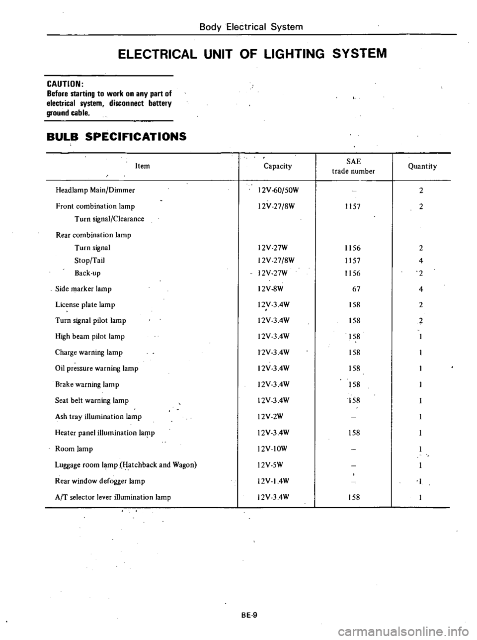
BULB
SPECIFICATIONS
Item
Headlamp
Main
Dilnmer
Front
combination
lamp
Turn
signal
Clearance
Rear
combination
lamp
Turn
signal
Stop
Tail
Back
up
Side
marker
lamp
License
plate
lamp
Turn
signal
pilot
lamp
High
beam
pilot
lamp
Charge
warning
lamp
Oil
pressure
warning
lamp
Brake
warning
lamp
Seat
belt
warning
lamp
Ash
tray
illumination
lamp
Heater
panel
illumination
laf
lp
Room
lamp
Luggage
room
lamp
Hatchback
and
Wagon
Rear
window
defogger
lamp
AfT
selector
lever
illumination
lamp
Capacity
SAE
trade
number
12V
60
50W
l2V
27
8W
1157
l2V
27W
12V
27
8W
12V
27W
12V
8W
l2V
3
4W
l2V
3
4W
l2V
3
4W
12V
3
4W
12V
3
4W
12V
3
4W
12V
3
4W
l2V2W
l2V
3
4W
l2V
lOW
Quantity
2
2
1156
2
1157
4
1156
2
67
4
158
2
158
2
158
158
158
158
158
158
l2V
5W
12V
14W
12V
3
4W
158
BE
9
Page 455 of 548

REMOVAL
AND
INSTALLATION
For
lamp
Note
a
Disconnect
battery
ground
cable
before
starting
to
work
b
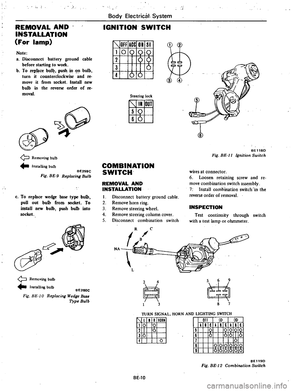
To
repJaoe
bull
push
ill
n
bulb
turn
it
counterclockwise
and
re
move
it
from
socket
Install
new
bulb
in
tbe
reverse
order
of
re
moval
9
Removing
bulb
Installing
bulb
BE259C
Fig
BE
9
Replacing
Bulb
c
To
repbce
wedge
base
type
bulb
puD
out
bulb
from
socket
To
inslaD
new
bulb
pusb
bulb
into
socket
Removing
bulb
Installing
bulb
Fig
BE
10
BE260C
R
eplac
ing
Wedge
BlUe
Type
Bulb
Body
Electrical
System
IGNITION
SWITCH
OFF
ICC
01
ST
I
0
0
61
1
ot
Steering
lock
5
I
OUT
I
Iso
16
6
I
T
BEll8D
Fig
BE
II
Ignition
Switch
COMBINATION
SWITCH
wires
at
connector
6
Loosen
retaining
screw
and
Ie
move
combination
switch
assembly
7
lnstaD
combination
switch
in
the
reverse
order
of
removal
REMOVAL
AND
INSTALLATION
I
Disconnect
battery
ground
cable
2
Remove
horn
ring
3
Remove
steering
wheel
4
Remove
steering
column
cover
5
Disconnect
combination
switch
INSPECTION
Test
continuity
through
switch
with
a
test
lamp
or
ohmmeter
TURN
SIGNAL
HORN
AND
LIGHTING
SWITCH
1
1
R
HORMI
119
0
I
12
I
6
I
136
I
II
0
I
III
I
F
c
I
c
I
c
15
0
QQOQ
16
6
56
I
5
11
0
II
000Q
10
9
000000
BE119D
Fig
BE
12
Combination
Switch
BE
l0
Page 484 of 548

Body
Electrical
System
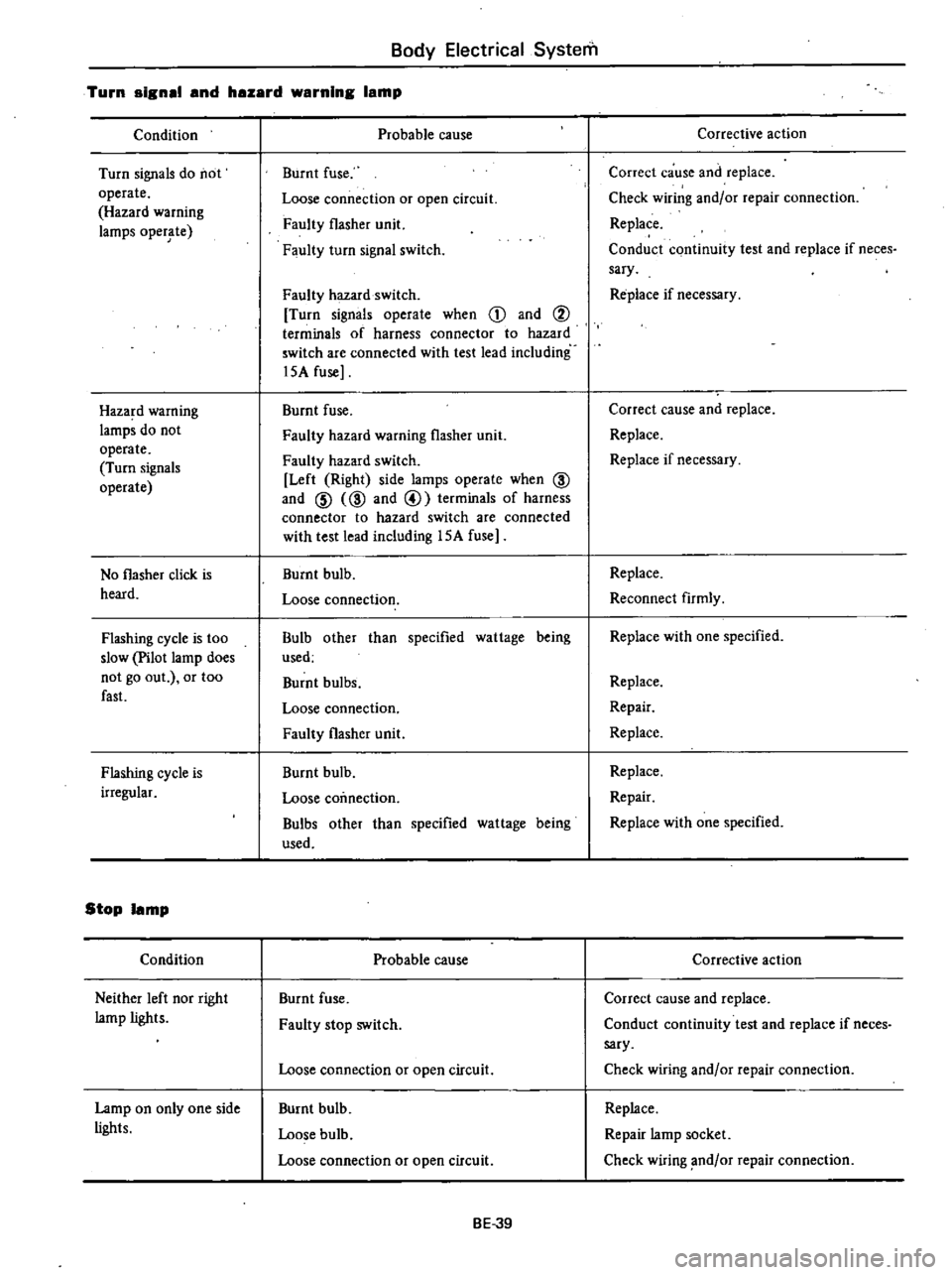
Turn
signsl
snd
hszsrd
wsrnlng
Ismp
Condition
Turn
signals
do
not
operate
Hazard
warning
lamps
oper
te
Haza
d
warning
lamps
do
not
operate
Turn
signals
operate
No
flasher
click
is
heard
Flashing
cycle
is
too
slow
Pilot
lamp
does
not
go
out
or
too
fast
Flashing
cycle
is
irregular
Stop
Ismp
Condition
Neither
left
nor
right
lamp
lights
Lamp
on
only
one
side
lights
Probable
cause
Burnt
fuse
Loose
connection
or
open
circuit
Faulty
flasher
unit
Faulty
turn
signal
switch
Faulty
hazard
switch
Turn
signals
operate
when
CD
and
i
terminals
of
harness
connector
to
hazard
switch
are
connected
with
test
lead
including
l5A
fuse
Burnt
fuse
Faulty
hazard
warning
flasher
unit
Faulty
hazard
switch
Left
Right
side
lamps
operate
when
@
and
@
@
and
@
terminals
of
harness
connector
to
hazard
switch
are
connected
with
test
lead
including
l5A
fuse
Burnt
bulb
Loose
connection
Bulb
other
than
specified
wattage
being
used
Burnt
bulbs
Loose
connection
Faulty
flasher
unit
Burnt
bulb
Loose
coimection
Bulbs
other
than
specified
wattage
being
used
Probable
cause
Burnt
fuse
Faulty
stop
switch
Loose
connection
or
open
circuit
Burnt
bulb
Loose
bulb
Loose
connection
or
open
circuit
BE
39
Corrective
action
Correct
cause
and
replace
Check
wiring
and
or
repair
connection
Replace
Conduct
continuity
test
and
replace
if
neces
sary
Re
place
if
necessary
Correct
cause
and
replace
Replace
Replace
if
necessary
Replace
Reconnect
firmly
Replace
with
one
specified
Replace
Repair
Replace
Replace
Repair
Replace
with
one
specified
Corrective
action
Correct
cause
and
replace
Conduct
continuity
test
and
replace
if
neces
sary
Check
wiring
and
or
repair
connection
Replace
Repair
lamp
socket
Check
wiring
nd
or
repair
connection