wheel bolts DATSUN 610 1969 Owner's Manual
[x] Cancel search | Manufacturer: DATSUN, Model Year: 1969, Model line: 610, Model: DATSUN 610 1969Pages: 171, PDF Size: 10.63 MB
Page 88 of 171
the
castle
nut
and
detach
the
tie
rod
from
the
knuckle
arm
5
Remove
the
tension
rod
securing
nuts
Fig
J
7
remove
the
bolts
and
withdraw
the
tension
rod
Withdraw
the
nut
shown
arrowed
in
FigJ
8
and
remove
the
stabilizer
6
Support
the
engine
with
suitable
lifting
tackle
so
that
the
engine
mounting
bolts
can
be
removed
and
the
suspension
crossmember
detached
from
the
engine
FigJ
9
7
Place
ajack
under
the
crossmember
Remove
the
bolts
indicated
in
Fig
J
IO
and
separate
the
crossmember
from
the
body
8
Remove
the
strut
assembly
upper
attachment
self
locking
nuts
at
both
sides
Fig
J
ll
and
lower
the
front
suspension
assembly
to
remove
it
from
the
vehicle
FRONT
AXLE
AND
SUSPENSION
ASSEMBLY
Installation
Installation
is
a
reversal
of
the
removal
procedure
noting
the
following
points
Make
sure
that
all
rubber
parts
are
free
from
wear
and
deterioration
Any
part
of
the
suspension
assembly
which
has
been
damaged
or
distorted
must
be
replaced
The
front
wheel
alignment
should
be
checked
after
completing
the
installation
a
brief
description
is
given
at
the
end
of
this
section
Camber
and
castor
angles
are
preset
and
cannot
be
adjusted
SPRING
AND
STRUf
ASSEMBLY
Removal
and
Installation
The
strut
assembly
consists
of
the
outer
casing
piston
rod
piston
rod
guide
and
cylinder
etc
An
exploded
view
of
the
components
is
given
in
Fig
J
12
The
inner
components
must
be
replaced
as
a
complete
assembly
Replacement
and
overhaul
procedures
for
the
inner
components
together
with
the
removal
of
the
front
springs
should
only
be
carried
out
by
a
specialist
Datsun
workshop
The
strut
assembly
can
be
removed
prior
to
dismantling
by
following
the
procedures
outlined
below
Jack
up
the
front
of
the
vehicle
and
support
it
on
stands
2
Disconnect
the
brake
hose
from
the
strut
assembly
bracket
as
previously
described
under
the
heading
FRONT
AXLE
and
SUSPENSION
ASSEMBLY
Removal
3
Remove
the
stabilizer
bar
and
tension
rod
from
the
trans
verse
links
Loosen
and
remove
the
knuckle
arm
fixing
bolts
Fig
J
9
And
separate
the
strut
assembly
from
the
ball
joints
4
Remove
the
strut
assembly
upper
attachment
self
locking
nuts
Fig
J
11
and
withdraw
the
strut
assembly
from
the
body
Fig
J
13
Installation
is
a
reversal
of
the
removal
procedure
Ensure
that
the
bolts
are
tightened
to
the
specified
torque
readings
given
under
TIGHTENING
TORQUES
SPRING
AND
STRUT
ASSEMBLY
Dismantling
and
Assembly
Care
must
be
taken
when
dismantling
the
assembly
to
ensure
that
aU
parts
are
maintained
in
a
clean
condition
Clamp
the
suspension
strut
assembly
in
a
vice
and
fit
the
special
attachment
ST
2770000
I
to
the
lower
end
of
the
strut
Prise
off
the
dust
cover
snap
ring
Use
the
coil
spring
compressor
ST
35650001
to
slightly
compress
the
spring
Remove
the
self
locking
nut
and
take
off
the
mounting
insulator
thrust
bearing
spring
seat
and
bump
rubber
Slacken
the
spring
compressor
and
remove
the
spring
Push
down
the
shock
absorber
piston
until
it
bottoms
and
remove
the
gland
packing
with
the
special
tool
ST
35500001
Fig
J
14
Remove
the
O
ring
from
the
piston
rod
guide
and
lift
out
the
piston
rod
and
cy
linder
assembly
00
NOT
separate
the
piston
and
cylinder
which
are
serviced
as
a
complete
assembly
Drain
all
fluid
from
the
suspension
unit
and
shock
absorber
assembly
Wash
all
parts
thoroughly
not
rubber
parts
in
petrol
or
a
suitable
solvent
The
gland
packing
and
0
ring
must
be
renewed
at
each
overhaul
Always
refill
with
the
correct
grade
of
fresh
oil
in
accordance
with
the
information
in
the
table
below
ATSUGI
KAYABA
Part
No
54302
UO
100
UOl10
325
cc
332
cc
54302
3
U0500
1
54302
N
1200
325
cc
300
cc
The
oil
quantity
is
extremely
critical
as
it
will
affect
the
damping
power
of
the
shock
absorber
To
assemble
fit
the
rubber
O
ring
on
the
top
of
the
piston
rod
and
refit
the
gland
packing
Take
care
that
the
oil
seal
does
not
become
damaged
during
the
latter
operation
Lift
the
piston
rod
up
by
approximately
90
mm
3
5
in
before
tightening
the
gland
packing
to
facilitate
bleeding
then
tighten
the
packing
to
a
torque
reading
of
7
13
kgm
51
94Jb
ft
Bleed
the
shock
absorber
by
pumping
the
piston
rod
up
and
down
until
the
pressure
is
the
same
in
both
directions
Position
the
coil
spring
bump
rubber
spring
seat
and
dust
cover
on
the
top
of
the
piston
rod
The
piston
rod
must
be
in
the
fully
extended
position
Compress
the
spring
fit
the
strut
mounting
insulator
and
bearing
assembly
Tighten
the
self
locking
nut
to
a
torque
reading
of
6
7
5
kgm
43
541b
ft
SPRING
AND
STRUT
ASSEMBLY
Installation
Installation
is
a
reversal
of
the
removal
procedure
Thoroughly
grease
the
parts
marked
in
Fig
J
15
Tighten
the
fixing
bolts
to
the
torque
readings
given
in
TIGHfENING
TORQUES
TRANSVERSE
LINK
AND
LOWER
BALL
JOINT
Removal
The
transverse
link
with
rubber
bushing
is
connected
to
the
suspension
crosSlTIember
by
a
mounting
bolt
as
shown
in
Fig
J
11
and
to
the
strut
assembly
via
the
lower
ball
joint
87
Page 89 of 171
Removal
from
the
vehicle
can
be
carried
out
in
the
following
manner
Jack
up
the
front
of
the
vehicle
and
support
it
on
stands
2
Remove
the
stabilizer
bar
and
tension
rod
from
the
transverse
link
as
previously
described
Remove
the
knuckle
arm
fixing
bolts
and
separate
the
ball
joint
from
the
strut
asse
m
bly
3
Remove
the
transverse
link
mounting
bolt
Fig
J
16
and
detach
the
transverse
link
from
the
suspension
member
Remove
the
cotter
pin
from
the
knuckle
arm
castle
nut
and
remove
the
knuckle
arm
from
the
ban
joint
Unfasten
the
ball
joint
securing
nut
and
withdraw
the
ball
joint
from
the
transverse
link
r
The
bushing
can
be
withdrawn
from
the
transverse
link
using
a
press
and
the
special
tools
shown
in
Fig
J
17
TRANSVERSE
LINK
AND
LOWER
BALL
JOINT
Inspection
The
transverse
link
bushing
is
shown
in
Fig
J
18
If
the
rubber
and
inner
tube
joints
are
melted
or
cracked
the
complete
transverse
link
assembly
must
be
replaced
The
ban
joint
cannot
be
dismantled
and
should
be
replaced
if
the
dust
cover
is
split
or
if
the
axial
play
of
the
joint
exceeds
1
0
mm
0
039
in
Oleck
the
axial
play
with
a
spring
balance
The
force
required
at
the
cotterpin
hole
pOsition
is
between
6
6
1
I
3
kg
15
25
lb
Lubricate
the
ball
joint
with
multi
purpose
grease
every
50
000
km
30
000
miles
or
two
year
whichever
comes
first
A
grease
nipple
must
be
installed
in
place
of
the
plug
See
Fig
J
19
and
the
old
grease
completely
replaced
If
a
high
pressure
grease
gun
j
used
make
sure
that
the
grease
is
injected
slowly
and
is
not
forced
out
through
the
joint
clamp
Remove
the
grease
nipple
and
replace
the
plug
TRANSVERSE
LINK
AND
BALL
JOINT
Installation
Installation
is
a
reversal
of
the
removal
procedure
noting
the
following
points
Remove
all
rust
from
the
transverse
link
bushing
interior
with
a
piece
of
emery
cloth
The
bushing
and
transverse
link
bore
should
be
wetted
with
soapy
water
so
that
the
bushing
can
be
more
easily
inserted
Fit
the
bushing
into
the
transverse
link
using
the
special
tool
ST
36700000
Adjust
the
bushing
inner
tubes
so
that
the
distances
from
the
transverse
link
collar
ends
are
equal
at
both
sides
88
Install
the
lower
ball
joint
on
the
transverse
link
and
tighten
the
installation
bolt
to
a
torque
reading
of
1
9
5kgm
14
18Ib
ft
Oean
the
knuckle
arm
and
the
ball
joint
stud
install
the
knuckle
arm
on
the
ball
joint
and
tighten
the
castle
nut
to
a
torque
reading
of
5
5
74
kgm
4o
53Ib
ft
fit
the
cotterpin
and
bend
it
over
Apply
sealing
agent
over
the
ball
joint
castle
nut
to
prevent
the
formation
of
rust
Locate
the
knuckle
arm
beneath
the
strut
assembly
and
tighten
the
mounting
bolts
to
a
torque
reading
of
4
9
63kgm
35
46Ib
ft
Make
sure
that
the
shorter
of
the
bolts
is
fitted
at
the
front
Install
the
transverse
link
on
the
suspension
crossrnember
and
temporarily
tighten
the
mounting
bolts
Make
sure
that
the
nut
faces
the
front
of
the
car
and
not
the
bolt
head
Fit
the
tension
rod
and
stabilizer
bar
Lower
the
vehicle
and
remove
the
jack
Tighten
the
trans
verse
link
mounting
bolts
to
a
torque
reading
of
9
0
10
0
kgm
65
72
Ib
ft
with
the
vehicle
unladen
FRONT
WHEEL
ALIGNMENT
The
castor
and
camber
angles
are
preset
and
cannot
be
adjusted
If
the
angles
do
not
conform
with
the
fIgures
in
Techni
al
Data
then
a
check
must
be
made
for
damage
to
the
uspenSlon
system
Wheel
alignment
is
carried
out
with
the
tyres
mflated
to
the
correct
pressures
and
with
the
vehicle
on
a
level
surface
The
toe
in
should
be
checked
and
adjusted
if
necessary
by
slackening
the
locknuts
FigJ
20
and
turning
the
track
rods
by
an
equal
amount
until
the
correct
toe
in
is
achieved
The
standard
length
between
the
ball
joints
is
309
5
mm
12
19
in
for
the
1400
and
1600
cc
models
and
105
5
mm
4
14
in
for
the
1800
cc
models
ADJ
USTING
THE
STEERING
ANGLE
The
steering
angle
at
the
full
lock
positions
must
be
checked
with
the
front
wheels
placed
on
a
turntable
Adjust
ment
can
be
made
changing
the
length
of
the
stopper
bolt
shown
arrowed
in
FigJ
21
The
clearance
between
the
tyre
and
tension
rod
should
be
30
mm
1
181
in
or
more
and
can
be
increased
if
necessary
by
extending
the
length
of
the
stopper
bolt
The
bolt
length
should
not
exceed
27
5
mm
1
083
in
when
the
adjustment
is
completed
Steering
angle
figures
are
given
in
Technical
Data
at
the
end
of
this
section
Page 92 of 171
SteerIng
DEsn
IPTION
S
i
EERlNG
MaintenaDce
STEERING
WHEEL
AND
STEERING
GEAR
Removal
and
Installation
STEERING
GEAR
Dismantling
STEERING
GEAR
Inspection
and
Adjustment
DESCRIPTION
A
worm
and
recirculating
ball
type
steering
system
is
fitted
to
the
vehicle
the
component
parts
of
the
steering
gear
are
shown
in
Fig
K
I
The
steering
linkage
consists
of
the
centre
tie
rod
pitman
ann
idler
arm
outer
tie
rods
and
the
knuckle
arms
as
shown
in
Fig
K
2
A
collapsible
steering
column
assembly
can
be
fitted
to
the
vehicle
to
protect
the
driver
from
injury
in
a
head
on
collision
Details
of
this
type
of
assembly
are
given
under
the
appropriate
heading
STEERING
Maintenance
O1eck
the
oil
level
in
the
steering
box
every
10
000
km
6
000
miles
and
top
up
with
recommended
lubricant
if
necessary
Grease
the
steering
linkage
every
50
000
km
30
OOO
miles
It
will
be
necessary
to
replace
the
plug
in
the
tie
rod
ball
joints
with
a
grease
nipple
for
this
operation
as
previously
described
in
the
section
FRONT
SUSPENSION
Use
a
grease
gun
to
completely
replace
the
old
grease
with
new
grease
making
SUfe
that
the
grease
is
not
forced
from
under
the
cover
clamp
if
a
high
pressure
gun
is
used
STEERING
WHEEL
AND
STEERING
GEAR
Removal
1
Take
out
the
retaining
bolts
and
remove
the
horn
ring
remove
the
steering
wheel
nut
Fig
K
3
and
pull
off
the
steering
wheel
The
special
tool
ST
27180000
should
be
used
if
available
2
Disconnect
the
battery
leads
remove
the
steering
column
shell
covers
and
the
turn
signal
and
lighting
switch
assembly
3
On
vehicles
fitted
with
steering
column
gear
change
assemblies
the
gear
lever
must
be
removed
from
the
control
rod
assembly
Unscrew
the
retaining
boltg
and
disconnect
the
gear
lever
4
Remove
the
bolts
from
the
steering
column
upper
clamp
Fig
K
4
and
the
bolts
holding
the
lower
plate
Fig
K
5
5
If
the
vehicle
is
fitted
with
steering
column
gear
change
remove
the
cotterpin
from
the
trunnion
and
detach
the
gearchange
rod
and
selector
rod
from
the
change
lever
and
selector
lever
STEERING
GEAR
Assembly
and
Adjustment
COLLAPSIBLE
STEERING
COLLAPSIBLE
STEERING
Removal
and
Inspection
COLLAPSIBLE
STEERING
Installation
STEERING
LINKAGE
6
Remove
the
bolts
securing
the
steering
gear
housing
to
the
car
body
Fig
K
6
and
pull
the
steering
gear
towards
the
engine
compartment
Remove
the
gearchange
control
from
the
steering
gear
assembly
as
described
in
the
section
GEARBOX
STEERING
WHEEL
AND
STEERING
GEAR
Installation
Installation
is
a
reversal
of
the
removal
procedure
When
the
installation
has
been
completed
make
sure
that
the
steering
wheel
can
be
turned
smoothly
and
is
correctly
aligned
The
free
travel
of
the
steering
wheel
should
be
between
2S
30mm
0
9B
1
18
in
Tighten
the
steering
wheel
locknut
to
a
torque
reading
of
4
0
5
0
kgm
29
36Ib
ft
and
the
steering
column
upper
clamp
and
plate
bolts
to
a
torque
reading
of
1
3
1
8
kgm
94
1
3
Ib
ft
Ensure
that
the
steering
box
is
topped
up
to
the
correct
level
with
recommended
lubricant
STEERING
GEAR
Dismantling
Remove
the
pitman
arm
retaining
nut
and
pull
out
the
arm
The
special
puller
ST
27140000
should
be
used
if
available
Remove
the
drain
plug
from
the
steering
gear
housing
and
drain
the
oil
Slacken
the
adjusting
screw
nut
and
turn
the
sector
shaft
adjusting
screw
a
few
turns
in
the
anti
clockwise
direction
Remove
the
sector
shaft
cover
retaining
bolts
and
pull
the
sector
shaft
cover
and
sector
shaft
from
the
gear
housing
Fig
K
7
Remove
the
bolts
securing
the
column
jacket
to
the
gear
housing
and
carefully
withdraw
the
main
column
jacket
assembly
from
the
gear
housing
Fig
K
B
NOTE
The
ball
must
not
be
allowed
to
run
to
either
end
of
the
worm
or
the
ends
of
the
ball
guides
will
be
damaged
Pull
the
column
assembly
from
the
column
jacket
Remove
the
sector
shaft
oil
seal
and
take
out
the
rear
bearing
outer
race
from
the
column
jacket
with
a
suitable
puller
Withdraw
the
bearing
inner
races
from
the
front
and
fear
worm
bearings
Remove
the
column
shaft
bearing
91
Page 93 of 171

inte
r
E
lliIl
@
Pl
r
I
I
ill
i
1
Steeri
K
wh
l
2
Column
clamp
3
Steerinx
column
4
LoWf
T
moun
ins
f
Jurge
5
Rubber
coupling
6
St
ring
galf
7
Drop
arm
8
Centre
tie
rod
9
Outer
tie
rod
10
Idler
ann
fit
@
@
Fig
K
l
The
steering
system
components
Fig
K
3
Removing
the
steering
wheel
nut
FIg
K
S
Steering
column
cover
plate
92
y
AA
11
N
E
l
@
@
@I
@
@
J
Drop
Urn
2
Centre
tie
rod
J
Outer
tie
rod
4
Tie
rod
outer
ocket
5
Ti
rod
inner
rocket
6
ldkr
arm
auembly
Fig
K
2
The
steering
linkage
component
Fig
KA
Steering
column
upper
attachment
bolts
Fig
K
6
Removing
the
steering
gear
mounting
bolts
Page 94 of 171
STEERING
GEAR
Inspection
and
Adjustment
Thoroughly
clean
all
parts
and
examine
them
for
signs
of
wear
or
damage
Replace
any
comIK
nent
found
to
be
un
satisfactory
It
is
advisable
to
renew
the
assemblies
if
the
steering
column
or
ball
nut
assembly
is
defective
as
the
adjustment
procedures
required
to
overhaul
the
units
are
rather
involved
The
dismantling
and
adjustment
procedures
for
the
ball
nut
assembly
can
be
carried
out
in
the
following
manner
if
it
is
decided
that
overhaul
procedures
are
to
be
carried
out
Ball
nut
Remove
the
ball
guide
tube
clamp
withdraw
the
guide
tubes
from
the
ball
nut
and
collect
the
steel
balls
Turn
the
nut
upside
down
and
rotate
the
steering
column
backwards
and
forwards
until
all
36
steel
balls
have
dropped
out
of
the
ball
nut
Pull
the
ball
nut
from
the
column
Inspect
the
ball
guide
tubes
and
make
sure
that
they
are
not
damaged
Pay
particular
attention
to
the
ends
of
the
tubes
that
pick
up
the
balls
from
the
helical
path
Renew
the
tubes
if
they
are
unsatisfactory
Check
the
steel
balls
and
the
ball
nut
for
wear
and
replace
the
complete
unit
if
necessary
Assemble
the
ball
nut
on
the
worm
with
the
ball
guide
holes
upwards
Drop
18
balls
into
each
of
the
two
holes
on
the
same
side
of
the
ball
nut
until
all
36
balls
are
installed
The
column
should
be
gradually
turned
away
from
the
hole
being
filled
and
if
the
balls
are
stopped
by
the
end
of
the
column
hold
down
those
already
installed
with
a
clean
rod
or
punch
while
turning
the
column
several
times
in
the
reverse
direction
The
filling
of
the
circuit
can
then
be
continued
but
it
may
be
necessary
to
turn
the
column
backwards
and
forwards
holding
the
balls
down
first
in
one
hole
and
then
the
other
to
close
the
spaces
and
completely
fill
the
circuit
Place
the
remaining
22
balls
in
the
ball
guide
halves
11
balls
for
each
half
Fit
the
other
half
of
the
guide
tube
to
each
f11led
half
hold
the
two
halves
together
a
ld
plug
each
open
end
with
vaseline
to
prevent
the
balls
falling
out
Push
the
guide
tubes
into
the
ball
nut
guide
holes
and
assemble
the
guide
tube
clamp
Inspection
Oteck
the
axial
clearance
between
the
ball
nut
and
the
balls
If
the
clearance
exceeds
0
08
mrn
0
003
in
the
complete
unit
must
be
replaced
Inspect
the
gear
teeth
of
the
sector
shaft
for
wear
or
damage
Replace
any
worn
or
imperfect
bearings
Examine
the
steering
column
shaft
for
straightness
and
check
that
the
maximum
deflection
does
not
exceed
0
2mm
0
008
in
at
point
C
in
Fig
K
9
when
the
shaft
is
supported
at
points
A
and
B
Check
the
sector
shaft
and
steering
column
shaft
serrations
for
wear
Renew
the
parts
as
necessary
STEERING
GEAR
Assembly
and
Adjustment
Grease
the
lip
of
the
oil
seal
and
press
it
into
the
housing
Insert
the
column
assembly
into
the
column
jacket
and
fit
the
worm
bearing
shims
to
the
gear
housing
Install
the
flange
securing
bolts
and
tighten
them
to
a
torque
reading
of
1
8
2
5
kgm
13
18lb
ft
If
a
new
column
bearing
assembly
is
fitted
it
must
be
filled
with
bearing
grease
and
cemented
to
the
column
The
preload
of
the
worm
bearing
can
be
adjusted
by
altering
the
thickness
of
the
worm
bearing
shim
Four
shim
thicknesses
are
available
in
sizes
of
0
76
0
254
0
127
0
050mm
0
0300
0
100
0
005
in
0
002
in
This
adjustment
check
is
carried
out
without
the
sector
shaft
fitted
and
with
the
worm
bearings
oiled
Install
the
steering
wheel
as
shown
in
Fig
K
9
use
a
spring
balance
as
indicated
to
check
that
the
force
required
to
turn
the
wheel
is
between
4
0
8
0
kg
cm
56
l120z
inch
Select
a
suitable
shim
from
the
sizes
given
Assemble
the
selector
shaft
adjuster
with
a
shim
into
the
sector
shaft
Measure
the
end
clearance
of
the
adjuster
with
a
feeler
gauge
as
shown
in
Fig
K
1
O
The
correct
clearance
is
0
01
0
03mm
0
0004
O
0012in
and
can
be
adjusted
by
varying
the
thickness
of
shim
Four
thicknesses
of
shim
are
available
as
follows
1
57
mm
0
0618
in
1
55
mm
0
0610
in
1
52
mm
0
0598
in
1
50
mm
0
0591
in
To
assemble
the
sector
shaft
into
the
gear
housing
rotate
the
column
by
hand
until
the
ball
nut
is
at
the
central
position
of
its
travel
so
that
the
centre
tooth
of
the
sector
shaft
enters
the
centre
tooth
space
of
the
ball
nut
Fit
a
new
gasket
and
push
the
sector
shaft
cover
and
sector
shaft
into
place
Ensure
that
a
certain
amount
of
play
is
present
between
the
rack
and
sector
teeth
before
tightening
the
cover
bolts
to
a
torque
reading
of
1
5
2
5
kgm
10
9
18
llb
ft
Temporarily
lock
the
adjusting
screw
with
the
locknut
Move
the
sector
shaft
several
times
from
the
pitman
arm
side
to
make
sure
that
it
turns
smoothly
Connect
the
pitman
arm
to
the
sector
shaft
taking
care
that
the
alignment
marks
on
the
arm
and
shaft
coincide
Adjust
the
backlash
with
the
steering
in
the
central
position
using
a
dial
gauge
as
shown
in
Fig
K
II
Turn
the
adjusting
screw
with
a
screwdriver
until
the
amount
of
free
movement
at
the
top
of
the
pitman
arm
is
within
O
lmm
0
0039
in
at
a
radius
of
127
mm
5
0
in
Lock
the
adjusting
screw
with
the
locknut
Fig
K
12
and
recheck
the
free
move
ment
Fill
the
steering
gear
housing
with
the
correct
amount
of
recommended
lubricant
Refit
the
steering
gear
to
the
vehicle
as
previously
described
Make
sure
that
the
steering
wheel
is
correctly
aligned
and
that
93
Page 96 of 171
the
system
operates
smoothly
COLLAPSIBLE
STEERING
The
collapsible
steering
column
is
designed
so
that
compression
occurs
when
the
vehicle
is
involved
in
a
head
on
collision
See
Fig
K
13
Two
forces
can
be
considered
when
a
collision
of
this
type
takes
place
These
being
the
primary
force
in
which
the
forward
motion
of
the
car
is
suddenly
halted
and
the
secondary
force
as
the
driver
continues
in
a
forward
direction
onto
the
steering
wheel
and
column
The
collapsible
column
is
designed
so
that
it
does
not
move
to
the
rear
i
e
into
the
driving
com
partment
when
the
primary
force
or
forward
motion
of
the
car
is
suddenly
halted
When
the
secondary
force
takes
place
as
the
driver
is
thrown
forward
the
column
jacket
gradually
collapses
and
partially
absorbs
the
amount
of
impact
The
collapsible
type
of
column
is
no
more
susceptible
to
damage
than
an
ordinary
column
when
it
is
installed
in
the
vehicle
however
when
a
collapsible
column
is
removed
it
must
be
carefully
handled
A
sharp
blow
on
the
end
of
the
shaft
or
gear
change
levers
dropping
or
leaning
on
the
assembly
can
cause
the
column
jacket
to
bend
particularly
at
the
bellows
part
which
absorbs
the
shock
The
steering
movement
is
transmitted
by
the
lower
shaft
and
upper
tube
The
lower
shaft
exterior
and
upper
tube
interior
are
tightly
fitted
together
with
four
plastic
pins
com
pletely
eliminating
any
gap
When
a
collision
occurs
the
plastic
pins
shear
and
the
lower
shaft
enters
the
upper
tube
this
action
will
cause
the
shaft
end
to
spread
and
the
lower
shaft
cannot
then
be
withdrawn
unless
an
extremely
high
load
is
applied
The
shaft
is
prevented
from
moving
towards
the
drivers
compartment
when
the
primary
force
takes
place
i
e
when
the
forward
motion
of
the
vehicle
is
suddenly
halted
by
the
three
stoppers
on
the
jacket
tube
The
steering
lock
collar
mounted
to
the
shaft
contacts
the
stoppers
and
prevents
a
rear
ward
movement
A
part
of
the
jacket
tube
is
specially
formed
to
act
as
an
energy
absorbing
part
of
the
collapsible
steering
The
upper
and
lower
guide
tubes
joined
with
polyacetal
resin
are
inserted
into
the
mesh
tube
so
that
energy
generated
by
a
collision
can
be
absorbed
as
smoothly
as
possible
with
a
low
load
The
steering
column
clamp
shown
in
Fig
K
14
is
secured
to
the
jacket
tube
and
body
by
bolts
with
two
aluminium
slidings
blocks
set
to
the
body
by
plastic
pins
An
impact
from
the
drivers
side
causes
the
plastic
pins
to
shear
and
leave
the
sliding
block
in
the
column
clamp
side
allowing
the
clamp
to
move
with
the
jacket
as
it
collapses
COLLAPSffiLE
STEERING
Removal
and
Inspection
Steering
Wheel
I
Disconnect
the
battery
earth
cable
2
Disconnect
the
horn
wiring
and
remove
the
horn
pad
3
Remove
the
steering
wheel
nut
using
the
special
puller
ST
27180000
Eig
K
15
Remove
the
column
shell
covers
Fig
K
16
and
the
turn
signal
switch
assembly
Column
shaft
4
Remove
the
cotter
pin
and
detach
the
shift
rod
Automatic
Transmission
Remove
the
bolt
securing
the
worm
shaft
and
coupling
Fig
K
17
5
Take
out
the
bolts
securing
the
column
tube
flange
to
the
dash
panel
and
the
bolts
securing
the
column
clamp
With
draw
the
steering
column
shaft
towards
the
car
interior
A
careful
check
should
be
made
to
ensure
that
the
assembly
is
not
damaged
in
any
way
Pull
out
the
lower
shaft
tap
the
column
clamp
towards
the
steering
wheel
end
and
remove
the
screws
securing
the
upper
and
lower
tubes
Separate
the
upper
and
lower
tubes
Remove
the
snap
ring
from
the
upper
end
of
the
column
pull
the
upper
jacket
down
and
separate
it
from
the
upper
jacket
tube
Take
care
not
to
damage
the
bearing
Remove
the
plain
washer
and
spring
from
the
upper
shaft
Check
the
column
bearings
for
damage
and
lack
of
smooth
ness
Apply
multi
purpose
grease
to
the
bearing
if
necessary
Inspect
the
jacket
tubes
for
signs
of
deformation
renew
the
tubes
if
necessary
Check
the
dimension
A
in
Fig
K
1B
to
make
SUfe
that
the
jacket
has
not
been
crushed
Check
the
dimension
B
Fig
K
14
COLLAPSffiLE
STEERING
Assembly
and
Installation
Assembly
is
a
reversal
of
the
dismantling
procedure
noting
the
following
points
Lubricate
the
column
bearing
the
spring
and
dust
seal
sliding
parts
Ensure
that
the
upper
shaft
steering
lock
hole
and
the
steering
lock
are
correctly
positioned
Fig
K
19
When
assembling
the
lower
shaft
take
care
to
coincide
the
notch
on
the
universal
joint
with
the
punched
mark
on
the
shaft
Coat
the
upper
and
lower
shaft
serrations
with
multi
purpose
grease
Set
the
steering
in
the
straight
ahead
position
and
fit
the
column
shaft
to
the
steering
gear
See
Fig
K
20
Insert
the
column
through
the
dash
board
and
install
it
to
the
gear
so
that
the
punch
mark
at
the
top
of
the
shaft
is
forced
upwards
Slide
the
universal
joint
to
the
steering
gear
and
temporarily
install
the
column
clamp
6
Fit
the
lower
cover
flange
7
and
tighten
the
column
clamp
bolts
Check
the
steering
wheel
alignment
with
the
wheels
in
the
straight
ahead
position
If
the
steering
wheel
and
steering
lock
are
misaligned
by
more
than
35
mm
I
4
in
from
the
vertical
position
femove
the
steering
wheel
and
re
centre
it
STEERING
LINKAGE
Removal
Jack
up
the
front
of
the
vehicle
and
support
it
on
stands
2
Remove
the
cotterpins
and
castle
nuts
fastening
the
tie
rod
ball
joints
to
the
knuckle
arms
95
Page 98 of 171
3
Free
the
ball
studs
from
the
knuckle
arms
by
placing
a
hammer
behind
the
boss
and
striking
the
opposite
side
with
another
hammer
4
Remove
the
centre
tie
rod
ball
studs
in
a
similar
manner
to
that
described
above
and
remove
the
centre
tie
rod
and
outer
tie
rods
as
an
assembly
5
Remove
the
idler
assembly
from
the
side
member
by
with
drawing
the
retaining
bolts
SfEERING
LINKAGE
Dismantling
Disconnect
the
tie
rods
from
the
centre
rod
Loosen
the
clamp
bolts
unscrew
the
socket
assembly
and
remove
the
socket
from
the
tie
rods
Remove
the
idler
arm
nut
and
dismantle
the
idler
assembly
Check
the
idler
arm
rubber
bushing
for
signs
of
damage
wear
or
play
and
replace
the
bushing
if
necessary
Oteck
the
centre
and
outer
tie
rod
for
damage
or
bending
Inspect
the
ball
joints
and
replace
them
i
the
amount
of
play
is
excessive
or
if
the
dust
cover
is
cracked
Further
infor
mation
can
be
found
in
the
section
FRONT
SUSPENSION
See
also
Figs
K
21
and
K
22
STEERING
LINKAGE
Assembly
and
Installation
Assembly
is
a
reversal
of
the
removal
procedure
noting
the
following
points
To
assembly
the
idler
arm
assembly
coat
the
outer
dia
meter
of
the
bushing
with
soapy
water
and
press
the
bushing
into
the
idler
arm
until
the
bushing
protrudes
equally
at
both
sides
Fit
the
idler
arm
body
in
the
rubber
bushing
Ensure
that
the
centre
line
of
the
idler
arm
is
parallel
with
the
centre
line
of
the
chassis
Installation
is
a
reversal
of
the
removal
procedure
The
outer
tie
rods
must
be
set
so
that
the
lengths
between
the
ball
stud
centres
are
309
5
mm
12
18
in
for
the
1400
and
1600cc
models
and
313
2
mm
12
33
in
for
the
1800cc
models
Tighten
the
ball
stud
nut
to
a
torque
reading
of
5
5
7
6
kgm
39
8
55Ib
ft
the
idler
ann
nut
to
5
5
7
6
kgm
39
8
55Ib
ft
and
the
pitman
arm
nut
to
14
kgm
lOllb
ft
The
front
wheel
alignment
toe
in
and
steering
angle
should
be
checked
and
adjusted
as
described
in
the
section
FRONT
SUSPENSION
TechnIcal
Data
Steering
type
Gear
ratio
Steering
angle
Inner
wheel
l800cc
Outer
wheel
1800
cc
Inner
wheel
1400
and
1600cc
Saloon
1400
and
1600cc
Estate
Outer
wheel
1400
and
1600cc
Saloon
1400
and
1600cc
Estate
Steering
wheel
play
1400
and
1600cc
Steering
wheel
play
1800cc
Standard
total
thickness
of
worm
bearing
shims
End
play
between
sector
shaft
and
adjusting
screw
Initial
turning
torque
of
worm
bearing
l800cc
models
1400
and
1600cc
models
Worm
and
recirculating
ball
15
0
I
370
380
30040
32040
380
380
30
31020
330
25
30mm
0
98
1
18
in
less
than
35mm
1
378
in
at
outer
rim
of
steering
wheel
1
5
mm
0
059
in
0
0
I
0
03mm
0
0004
0
0012
in
4
0
6
0
kg
cm
55
6
83
4
in
oz
4
0
8
0
kg
cm
55
6
112
in
oz
97
Page 100 of 171
BrakIng
System
DESCRIPTION
MASTER
CYLINDER
Removal
dismantling
and
Overhaul
BRAKE
LINES
Replacing
BRAKE
WARNING
LIGHT
SWITCH
FRONT
DRUM
BRAKE
Removal
inspection
and
Overhaul
REAR
DRUM
BRAKE
Removal
inspection
and
Overhaul
FRONT
DRUM
BRAKE
Adjusting
DESCRIPTION
The
vehicle
is
fitted
with
either
disc
brakes
or
two
leading
shoe
type
drum
brakes
for
the
front
wheels
and
leading
trailing
shoe
type
drum
brakes
for
the
rear
wheels
All
brakes
are
hydraulically
operated
from
the
brake
pedal
with
the
rear
brakes
additionally
operated
by
a
mechanical
handbrake
and
linkage
system
Either
a
single
or
a
tandem
master
cylinder
can
be
fitted
The
tandem
master
cylinder
provides
a
dual
braking
circuit
in
which
the
front
and
rear
brakes
are
separately
supplied
If
ODe
circuit
fails
the
other
circuit
will
still
operate
and
provide
a
reduced
but
efficient
braking
action
The
brake
pipes
are
double
wall
steel
tubes
and
are
galvanized
at
the
sections
beneath
the
vehicle
floor
to
prevent
corrosion
MASTER
CYLINDER
Removal
Either
a
tandem
or
single
master
cylinder
can
be
fitted
to
the
vehicle
Fig
L
I
shows
a
cross
sectional
view
through
the
tandem
master
cylinder
and
Fig
L
2
a
cross
sectional
view
through
the
single
master
cylinder
The
removal
and
dismantling
procedures
are
similar
for
both
types
and
are
carried
out
in
the
following
manner
1
Remove
the
clevis
pin
and
separate
the
brake
pedal
from
the
master
cylinder
push
rod
2
Disconnect
the
brake
tubes
from
the
master
cylinder
3
Remove
the
master
cylinder
mounting
bolts
withdraw
the
shims
and
take
out
the
master
cylinder
assembly
MASfER
CYLINDER
Dismantling
and
Overhaul
Drain
the
brake
fluid
from
the
cylinder
and
remove
the
stopper
bolt
Remove
the
dust
cover
the
snap
ring
the
stopper
ring
and
the
pusbrod
assembly
Take
out
the
primary
piston
and
secondary
piston
assemblies
and
the
piston
spring
Remove
the
valve
cap
and
take
out
the
valve
assembly
Oean
all
the
components
with
brake
fluid
and
check
them
for
wear
or
damage
Make
sure
that
the
cylinder
bore
and
piston
are
not
damaged
or
unevenly
worn
The
clearance
between
cylinder
and
piston
must
not
exceed
0
15mm
0
006
in
REAR
DRUM
BRAKE
Adjusting
FRONT
DISC
BRAKE
Friction
pads
FRONT
DISC
BRAKE
Removal
and
Dismantling
FRONT
DISC
BRAKE
Assembly
and
Installation
HANDBRAKE
Removal
and
Installation
BLEEDING
THE
HYDRAULIC
SYSTEM
BRAKE
PEDAL
ADJUSTMENT
Check
the
return
springs
for
damage
or
loss
of
tension
Replace
any
part
which
is
in
an
unsatisfactory
condition
MASfER
CYLINDER
Assembly
and
Installation
Assembly
of
the
master
cylinder
is
a
reversal
of
the
dismantling
procedure
noting
the
following
points
Wet
the
cylinder
bore
and
piston
etc
with
brake
fluid
before
assembling
Care
must
be
taken
to
prevent
dust
and
foreign
matter
entering
the
cylinder
and
reservoir
Ensure
that
cups
and
soals
are
not
damaged
when
locating
them
After
the
master
cylinder
is
reinstalled
the
system
must
be
bled
and
the
pedal
height
adjusted
as
described
under
the
appropriate
headings
BRAKE
LINES
Replacing
The
layout
of
the
metal
brake
pipes
and
flexible
hoses
is
shown
in
Fig
L
3
The
brake
pipes
can
be
removed
by
taking
off
the
flare
nuts
at
both
ends
of
the
pipe
and
removing
the
clips
securing
the
pipe
to
the
body
Similarly
the
brake
hoses
can
be
removed
by
taking
off
the
flare
nuts
Thoroughly
clean
the
pipe
or
hose
after
removing
from
the
vehicle
and
check
for
collapsing
cracking
or
rusting
of
the
pipe
and
for
signs
of
expansion
and
weakening
of
the
hose
Any
pipe
or
hose
which
is
not
in
a
satisfactory
condition
must
be
renewed
Remove
any
dust
from
the
brake
clip
and
replace
the
clip
if
the
vinyl
coating
is
torn
Installation
is
a
reversal
of
the
removal
procedure
Make
sure
that
the
brake
pipes
cannot
vibrate
against
any
part
of
the
vehicle
and
the
brake
hoses
are
not
twisted
and
rubbing
against
the
tyres
or
suspension
units
If
the
brake
hose
is
disconnected
from
the
three
way
connector
on
the
rear
axle
housing
it
will
be
necessary
to
fit
a
new
copper
sealing
washer
Do
not
overtighten
the
installation
flare
nuts
the
correct
tightening
torques
are
as
follows
Three
way
connector
master
cylinder
and
brake
hoses
1
5
1
8
kgm
II
13Ib
ft
Fill
the
master
cylinder
with
recommended
fluid
and
bleed
the
system
as
described
under
the
appropriate
heading
Make
sure
that
fluid
is
not
leaking
from
any
part
of
the
system
by
fully
depressing
the
brake
pedal
for
several
seconds
Check
the
pipes
and
connections
and
replace
any
defective
part
99
Page 101 of 171
inter
Il
IT
Q
riA
I
I
II
l
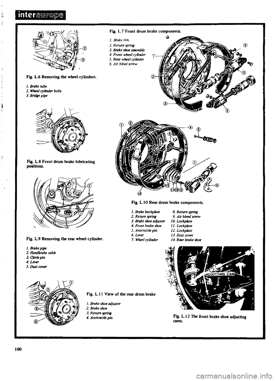
11
L
6
Removing
the
wbeel
cylindeIli
1
Brd
be
2
Wllul
cylinder
bolts
J
BridI
pip
I
g
L
8
Front
drum
brake
lubricating
positions
Fig
L
9
Removing
the
rear
wheel
cylinder
1
BnrIce
pip
2
Handblllke
cable
J
CIMJ
pin
4
Lnu
5
DustCI1ft
1
Fig
L
7
Front
drum
brake
components
J
T
Broke
rim
Return
Print
J
rhoe
cmembly
4
Front
wM
1
cylinder
5
Rear
wMtl
cylindu
6
A
iT
bleed
W
o
1
Fig
L
I0
Rear
drum
brake
components
1
BllIke
ckp
tzrc
2
RthUn
spring
3
Brate
ad
JlSkr
4
Front
brake
h
5
Anti
rottk
pin
6
Lever
7
Wheel
cylinder
8
Return
sprins
9
Air
bleed
JCrew
10
Lockp
orc
11
Lockp
tzrc
12
Lockplizte
13
Dust
cover
14
Rt
t1T
brake
dr
oe
Fig
L
II
View
of
the
rear
drum
brake
I
Broke
3Iwe
adjuJter
2
BraJ
e
shot
3
Retum
4
A
ntHuttle
pin
100
11
L
12
The
front
brake
shoe
adjusting
cams
Page 102 of 171
BRAKE
WARNING
UGHT
SWITCH
A
hydraulically
operated
warning
light
switch
is
located
in
the
engine
compartment
Fig
LA
The
front
and
rear
brake
systems
of
the
dual
circuit
are
connected
to
the
switch
which
provides
a
warning
via
the
warning
light
on
the
instrument
panel
when
a
pressure
difference
of
13
17
kg
sq
cm
185
242Ib
sq
in
occurs
between
the
front
and
rear
brake
systems
The
switch
cannot
be
repaired
and
must
be
renewed
if
faulty
FRONT
DRUM
BRAKE
Removal
1
Jack
up
the
front
of
the
vehicle
and
support
it
on
stands
2
Remove
the
brake
drum
and
the
hub
cap
and
hub
assembly
3
Disconnect
the
brake
pipe
at
the
bracket
on
the
front
suspension
strut
as
previously
described
in
the
section
FRONT
SUSPENSION
4
Unhook
the
two
return
springs
shown
in
Fig
L
5
and
remove
the
brake
shoes
5
Disconnect
the
bridge
pipe
3
in
Fig
L
6
and
remove
the
two
wheel
cylinders
6
Take
out
the
installation
bolts
and
withdraw
the
brake
backplate
from
the
spindle
FRONT
DRUM
BRAKE
Inspection
and
Overhaul
Examine
the
brake
drums
for
scoring
and
out
of
round
The
maximum
permissible
inner
diameter
of
the
drums
must
not
exceed
228
6mm
9
00
in
and
out
of
round
should
be
below
0
02mm
0
0008in
The
brake
shoe
linings
must
re
renewed
when
worn
down
to
a
thickness
of
1
5mm
0
06
in
or
below
Renew
the
linings
if
they
are
contaminated
in
any
way
or
incorrectly
seated
The
complete
set
of
linings
must
be
replaced
if
any
single
lining
is
unsatisfactory
O1eck
the
shoe
return
springs
and
if
they
have
become
weakened
replace
them
Withdraw
the
pistons
and
springs
from
the
wheel
cylinders
and
inspect
the
bore
of
the
cylinders
for
signs
of
wear
corrosion
or
damage
Renew
the
cylinder
and
the
piston
if
the
clearance
between
the
two
exceeds
O
15mm
0
006
in
Renew
the
rubber
boots
and
cups
FRONT
DRUM
BRAKE
Assembly
and
Installation
Assembly
and
installation
is
a
reversal
of
the
removal
and
dismantling
procedure
noting
the
fOllowing
points
Apply
a
thin
layer
of
special
grease
to
the
piston
cup
and
other
rubber
parts
when
assembling
the
wheel
cylinder
The
internal
components
of
the
cylinder
should
be
dipped
in
brake
fluid
and
assembled
whilst
still
wet
Install
the
wheel
cylinders
on
the
brake
backplate
and
smear
the
cylinder
backplate
and
cylinder
lever
fulcrum
with
grease
Fig
L
8
Tighten
the
backplate
mounting
bolts
to
a
torque
reading
of
2
7
3
7
kgm
19
5
26
71b
ft
Adjust
the
brake
shoes
and
bleed
the
hydraulic
system
as
described
under
the
appropriate
headings
REAR
DRUM
BRAKE
REMOVAL
Fig
L
IO
Jack
up
the
vehicle
at
the
rear
and
support
it
on
stands
Remove
the
road
wheel
2
Release
the
handbrake
remove
the
clevis
pin
3
from
the
rear
wheel
cylinder
lever
4
see
Fig
L
9
Disconnect
the
handbrake
cable
2
and
remove
the
return
spring
I
3
Remove
the
brake
drum
Remove
the
shoe
retainers
the
return
springs
and
brake
shoes
Fig
L
II
4
Disconnect
the
fluid
line
from
the
wheel
cylinders
and
plug
the
opened
end
to
prevent
to
loss
of
fluid
5
Remove
the
dust
cover
adjusting
shims
and
plates
then
remove
the
wheel
cylinder
from
the
backplate
6
The
brake
backplate
and
axle
shaft
assembly
can
be
with
drawn
if
necessary
by
taking
out
the
four
flange
bolts
and
removing
the
assembly
as
described
in
the
section
REAR
AXLE
AND
REAR
SUSPENSION
REAR
DRUM
BRAKE
Inspection
and
Overhaul
The
inspection
and
overhaul
procedures
fpr
the
rear
drum
brakes
are
similar
to
those
previously
described
for
the
front
drum
brakes
Tighten
the
brake
backplate
mounting
bolts
to
a
torque
reading
of
3
9
5
3
kgm
28
38Ib
ft
FRONT
DRUM
BRAKE
Adjusting
Jack
up
the
vehicle
and
pump
the
brake
pedal
several
times
With
the
brake
drum
installed
turn
one
of
the
adjusting
cams
clockwise
until
the
brake
shoe
is
in
contact
with
the
drum
This
operation
is
carried
out
from
the
rear
of
the
backplate
When
the
brake
shoe
contacts
the
drum
turn
the
cam
in
the
opposite
direction
until
the
shoe
is
just
clear
and
the
brake
drum
can
be
rotated
freely
by
hand
Repeat
the
operation
on
the
other
adjusting
cam
and
then
depress
the
brake
pedal
to
make
sure
that
the
brakes
are
working
correctly
The
adjusters
must
be
released
slightly
if
the
brake
drum
binds
when
turned
by
hand
Fig
L
12
shows
the
adjusting
cams
REAR
DRUM
BRAKE
Adjusting
Jack
up
the
vehicle
at
the
rear
and
pump
the
brake
pedal
several
times
Turn
the
brake
shoe
adjuster
Fig
L
13
until
the
101