change wheel DATSUN 610 1969 Workshop Manual
[x] Cancel search | Manufacturer: DATSUN, Model Year: 1969, Model line: 610, Model: DATSUN 610 1969Pages: 171, PDF Size: 10.63 MB
Page 52 of 171
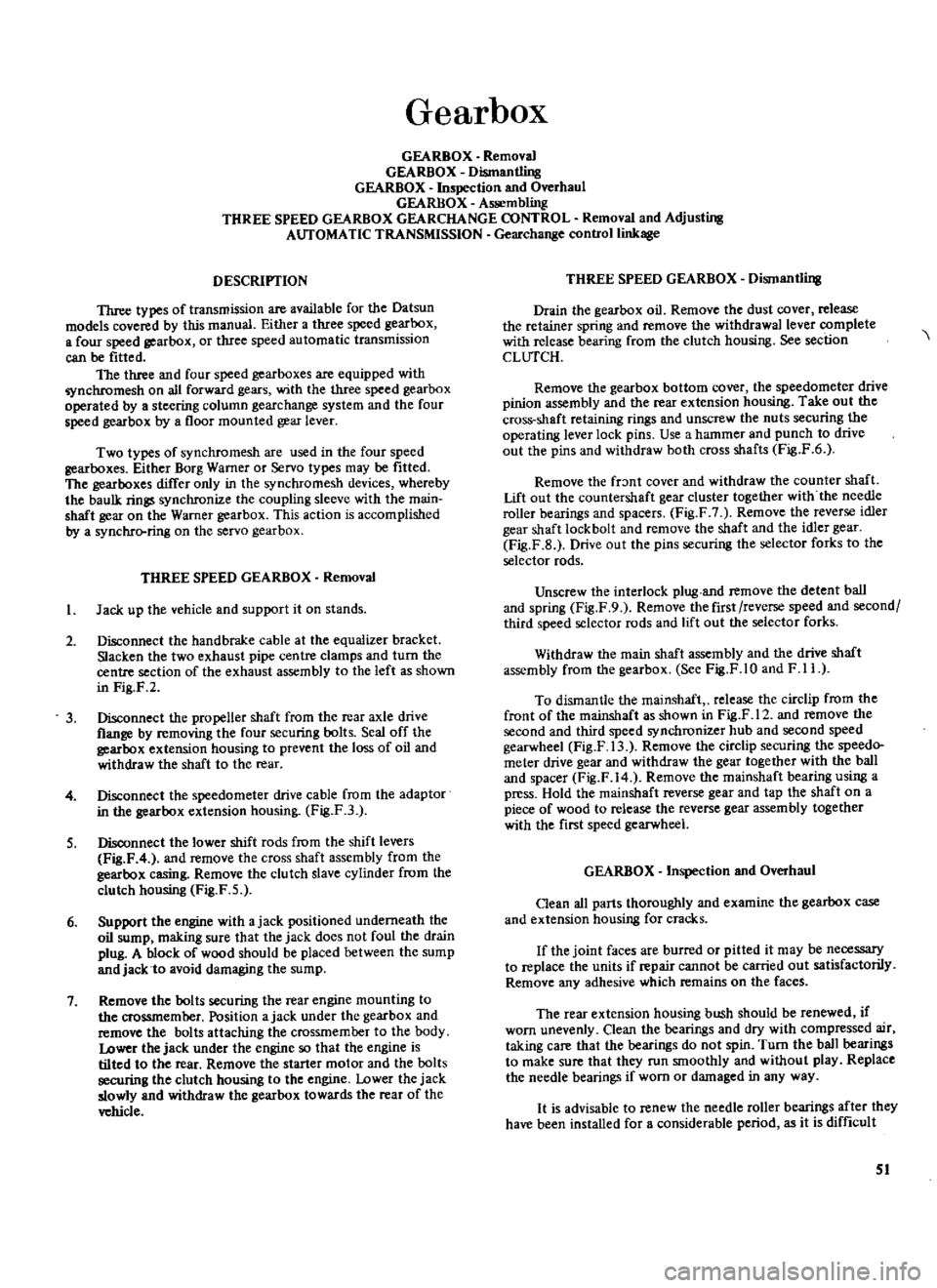
Gearbox
GEARBOX
Removal
GEARBOX
Dismantling
GEARBOX
Inspection
and
Overhaul
GEARBOX
Assembling
THREE
SPEED
GEARBOX
GEARCHANGE
CONTROL
Removal
and
Adjusting
AUTOMATIC
TRANSMISSION
Gearchange
control
linkage
DESCRIPTION
Three
types
of
transmission
are
available
for
the
Datsun
models
covered
by
this
manual
Either
a
three
speed
gearbox
a
four
speed
gearbox
or
three
speed
automatic
transmission
can
be
fitted
The
three
and
four
speed
gearboxes
are
equipped
with
nchromesh
on
all
forward
gears
with
the
three
speed
gearbox
operated
by
a
steering
column
gearchange
system
and
the
four
speed
gearbox
by
a
floor
mounted
gear
lever
Two
types
of
synchromesh
are
used
in
the
four
speed
gearboxes
Either
Borg
Warner
or
Servo
types
may
be
fitted
The
gearboxes
differ
only
in
the
synchromesh
devices
whereby
the
baulk
rings
synchronize
the
coupling
sleeve
with
the
main
shaft
gear
on
the
Warner
gearbox
This
action
is
accomplished
by
a
synchrcrring
on
the
servo
gearbox
THREE
SPEED
GEARBOX
Removal
I
Jack
up
the
vehicle
and
support
it
on
stands
2
Disconnect
the
hand
brake
cable
at
the
equalizer
bracket
Slacken
the
two
exhaust
pipe
centre
clamps
and
turn
the
centre
section
of
the
exhaust
assembly
to
the
left
as
shown
in
Fig
F
2
3
Disconnect
the
propeller
shaft
from
the
rear
axle
drive
flange
by
removing
the
four
securing
bolts
Seal
off
the
gearbox
extension
housing
to
prevent
the
loss
of
oil
and
withdraw
the
shaft
to
the
rear
4
Disconnect
the
speedometer
drive
cable
from
the
adaptor
in
the
gearbox
extension
housing
Fig
F3
S
Disconnect
the
lower
shift
rods
from
the
shift
levers
Fig
F
4
and
remove
the
cross
shaft
assembly
from
the
gearbox
casing
Remove
the
clutch
slave
cylinder
from
the
clutch
housing
Fig
F
5
6
Support
the
engine
with
ajack
positioned
underneath
the
oil
sump
making
sure
that
the
jack
does
not
foul
the
drain
plug
A
block
of
wood
should
be
placed
between
the
sump
and
jack
to
avoid
damaging
the
sump
7
Remove
the
bolts
securing
the
rear
engine
mounting
to
the
crossmember
Position
ajack
under
the
gearbox
and
remove
the
bolts
attaching
the
crossmember
to
the
body
Lower
the
jack
under
the
engine
so
that
the
engine
is
tilted
to
the
rear
Remove
the
starter
motor
and
the
bolts
securing
the
clutch
housing
to
the
engine
Lower
the
jack
slowly
and
withdraw
the
gearbox
towards
the
rear
of
the
vehicle
THREE
SPEED
GEARBOX
Dismantling
Drain
the
gearbox
oil
Remove
the
dust
cover
release
the
retainer
spring
and
remove
the
withdrawal
lever
complete
with
release
bearing
from
the
clutch
housing
See
section
CLUTCH
Remove
the
gearbox
bottom
cover
the
speedometer
drive
pinion
assembly
and
the
rear
extension
housing
Take
out
the
cross
shaft
retaining
rings
and
unscrew
the
nuts
securing
the
operating
lever
lock
pins
Use
a
hammer
and
punch
to
drive
out
the
pins
and
withdraw
both
cross
shafts
Fig
F
6
Remove
the
fr
mt
cover
and
withdraw
the
counter
shaft
Lift
out
the
countersbaft
gear
cluster
together
with
the
needle
roller
bearings
and
spacers
Fig
F
7
Remove
the
reverse
idler
gear
shaft
lock
bolt
and
remove
the
shaft
and
the
idler
gear
Fig
F
B
Drive
out
the
pins
securing
the
selector
forks
to
the
selector
rods
Unscrew
the
interlock
plug
and
remove
the
detent
ball
and
spring
Fig
F
9
Remove
the
first
reverse
speed
and
second
third
speed
selector
rods
and
lift
out
the
selector
forks
Withdraw
the
main
shaft
assembly
and
the
drive
shaft
assembly
from
the
gearbox
See
Fig
F
1O
and
F
11
To
dismantle
the
mainshaft
release
the
circlip
from
the
front
of
the
mainshaft
as
shown
in
Fig
F
12
and
remove
the
second
and
third
speed
synchronizer
hub
and
second
speed
gearwheel
Fig
F
13
Remove
the
circlip
securing
the
speedo
meter
drive
gear
and
withdraw
the
gear
together
with
the
ball
and
spacer
Fig
F
14
Remove
the
mainshaft
bearing
using
a
press
Hold
the
rnainshaft
reverse
gear
and
tap
the
shaft
on
a
piece
of
wood
to
release
the
reverse
gear
assembly
together
with
the
first
speed
gearwheel
GEARBOX
Inspection
and
Overhaul
Oean
all
parts
thoroughly
and
examine
the
gearbox
case
and
extension
housing
for
cracks
If
the
joint
faces
are
burred
or
pitted
it
may
be
necessary
to
replace
the
units
if
repair
cannot
be
carried
out
satisfactorily
Remove
any
adhesive
which
remains
on
the
faces
The
rear
extension
housing
bush
should
be
renewed
if
worn
unevenly
Clean
the
bearings
and
dry
with
compressed
air
taking
care
that
the
bearings
do
not
spin
Turn
the
ball
bearings
to
make
sure
that
they
run
smoothly
and
without
play
Replace
the
needle
bearings
if
worn
or
damaged
in
any
way
It
is
advisable
to
renew
the
needle
roller
bearings
after
they
have
been
installed
for
a
considerable
period
as
it
is
difficult
51
Page 60 of 171
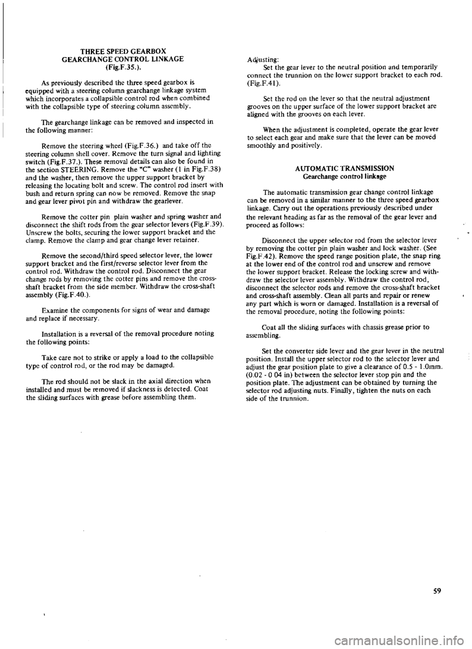
THREE
SPEED
GEARBOX
GEARCHANGE
CONTROL
LINKAGE
Fig
F
35
As
previously
described
the
three
speed
gearbox
is
equipped
with
a
steering
column
gearchange
linkage
system
which
incorporates
a
collapsible
control
rod
when
combined
with
the
collapsible
type
of
steering
column
assembly
The
gearchange
linkage
can
be
removed
and
inspected
in
the
following
manner
Remove
the
steering
wheel
Fig
F
36
and
take
off
the
steering
column
shell
cover
Remove
the
turn
signal
and
lighting
switch
Fig
F
37
These
removal
details
can
also
be
found
in
the
section
STEERING
Remove
the
C
washer
I
in
Fig
F
38
and
the
washer
then
remove
the
upper
support
bracket
by
releasing
the
locating
bolt
and
screw
The
control
rod
insert
with
bush
and
return
spring
can
now
be
removed
Remove
the
snap
and
gear
lever
pivot
pin
and
withdraw
the
gearlever
Remove
the
cotter
pin
plain
washer
and
spring
washer
and
disconnect
the
shift
rods
from
the
gear
selector
levers
Fig
F
39
Unscrew
the
bolts
securing
the
lower
support
bracket
and
the
clamp
Remove
the
clamp
and
gear
change
lever
retainer
Remove
the
second
third
speed
selector
lever
the
lower
support
bracket
and
the
first
reverse
selector
lever
from
the
control
rod
Withdraw
the
control
rod
Disconnect
the
gear
change
rods
by
removing
the
cotter
pins
and
remove
the
cross
shaft
bracket
from
the
side
member
Withdraw
the
cross
shaft
assembly
Fig
F
40
Examine
the
components
for
signs
of
wear
and
damage
and
replace
if
necessary
Installation
is
a
reversal
of
the
removal
procedure
noting
the
following
points
Take
care
not
to
strike
or
apply
a
load
to
the
collapsible
type
of
control
rod
or
the
rod
may
be
damaged
The
rod
should
not
be
slack
in
the
axial
direction
when
installed
and
must
be
removed
if
slackness
is
detected
Coat
the
sliding
surfaces
with
grease
before
assembling
them
Acijusting
Set
the
gear
lever
to
the
neutral
position
and
temporarily
connect
the
trunnion
on
the
lower
support
bracket
to
each
rod
Fig
F41
Set
the
rod
on
the
lever
so
that
the
neutral
adjustment
grooves
on
the
upper
surface
of
the
lower
support
bracket
are
aligned
with
the
grooves
on
each
lever
When
the
adjustment
is
completed
operate
the
gear
lever
to
select
each
gear
and
make
sure
that
the
lever
can
be
moved
smoothly
and
positively
AUTOMATIC
TRANSMISSION
Gearchange
control
linkage
The
automatic
transmission
gear
change
control
linkage
can
be
removed
in
a
similar
manner
to
the
three
speed
gearbox
linkage
Carry
out
the
operations
previously
described
under
the
relevant
heading
as
far
as
the
removal
of
the
gear
lever
and
proceed
as
follows
Disconnect
the
upper
selector
rod
from
the
selector
lever
by
removing
the
cotter
pin
plain
washer
and
lock
washer
See
Fig
F
42
Remove
the
speed
range
position
plate
the
snap
ring
at
the
lower
end
of
the
control
rod
and
unscrew
and
remove
the
lower
support
bracket
Release
the
locking
screw
and
with
draw
the
selector
lever
assembly
Withdraw
the
control
rod
disconnect
the
selector
rods
and
remove
the
cross
shaft
bracket
and
cross
shaft
assembly
Clean
all
parts
and
repair
or
renew
any
part
which
is
worn
or
damaged
Installation
is
a
reversal
of
the
removal
procedure
noting
the
following
points
Coat
all
the
sliding
surfaces
with
chassis
grease
prior
to
assembling
Set
the
converter
side
lever
and
the
gear
lever
in
the
neutral
position
Install
the
upper
selector
rod
to
the
selector
lever
and
adjust
the
gear
position
plate
to
give
a
clearance
of
0
5
I
Omm
0
02
0
04
in
between
the
selector
lever
stop
pin
and
the
position
plate
The
adjustment
can
be
obtained
by
turning
the
selector
rod
adjusting
nuts
Finally
tighten
the
nuts
on
each
side
of
the
trunnion
S9
Page 62 of 171
Gearbox
mode
Gearchange
type
Gear
ratios
I
st
gear
2nd
gear
3rd
gear
4th
gear
Reverse
Num
ber
of
teeth
on
mainshaft
Drive
gear
3rd
speed
2nd
speed
1st
speed
Reverse
Num
ber
of
teeth
on
counter
shaft
Driven
gear
3rd
speed
2nd
speed
1st
speed
Reverse
Reverse
idler
gear
Speedometer
Drive
gear
Driven
gear
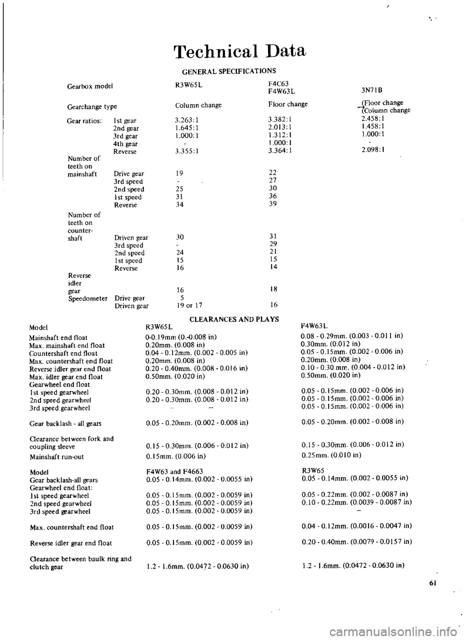
Technical
Data
GENERAL
SPECIFICATIONS
R3W65
L
F4C63
F4W63L
Column
change
Floor
change
3
263
1
3382
1
1
645
I
2
013
1
1
000
1
1
312
1
1
000
1
3
355
I
3
364
1
19
22
27
25
30
31
36
34
39
3N71B
iFloor
change
Column
change
2
458
1
1458
1
1
000
1
2
098
1
30
31
29
24
21
15
15
16
14
16
18
5
19
or
17
16
CLEARANCES
AND
PLAYS
Model
R3W65L
F4W63L
Mainshaft
end
float
0
0
19mm
0
0
008
in
0
08
0
29mm
0
003
0
0
II
in
Max
mainshaft
end
float
0
20mm
0
008
in
0
30mm
0
012
in
Countershaft
end
float
0
04
0
12mm
0
002
0
005
in
0
05
0
15mm
0
002
0
006
in
Max
countcrshaft
end
float
0
20mm
0
008
in
0
20mm
0
008
in
Reverse
idler
gear
end
float
0
20
0
40mm
0
008
0
016
in
0
10
0
30
mm
0
004
0
012
In
Max
idler
gear
end
float
0
50mm
0
020
in
0
50mm
0
020
in
Gearwheel
end
float
I
st
speed
gearwheel
0
20
0
30mm
0
008
0
012
in
0
05
0
15mm
0
002
0
006
in
2nd
speed
gearwheel
0
20
0
30mm
0
008
0
012
in
0
05
0
15mm
0
002
0
006
in
3rd
speed
gearwheel
0
05
0
15mm
0
002
0
006
in
Gear
backlash
all
gears
0
05
0
20mm
0
002
0
008
in
0
05
0
20mm
0
002
0
008
in
Oearance
between
fork
and
coupling
sleeve
0
15
0
30mm
0
006
0
012
in
0
15
0
30mm
0
006
0
012
in
Mallshaft
run
out
0
15mm
0
006
in
0
25mm
OmO
in
Model
F4W63
and
F4663
R3W65
Gear
backlash
all
gears
0
05
0
14mm
0
002
0
0055
in
0
05
0
14mm
0
002
0
0055
in
Gearwheel
end
float
1
st
speed
gearwheel
0
05
0
15mm
0
002
0
0059
in
0
05
O
22mm
0
002
0
0087
in
2nd
speed
gearwheel
0
05
0
15mm
0
002
0
0059
in
0
10
0
22mm
0
0039
0
0087
in
3rd
speed
gearwheel
0
05
0
15mm
0
002
0
0059
in
Max
countershaft
end
float
0
05
0
15mm
0
002
0
0059
in
0
04
0
12mm
0
0016
0
0047
in
Reverse
idler
gear
end
float
0
05
0
15mm
0
002
0
0059
in
0
20
0
40mm
0
0079
0
0157
in
Oearance
between
baulk
ring
and
clu
tch
gear
I
2
1
6mm
0
047
0
0630
in
12
1
6mm
0
0472
0
0630
in
61
Page 66 of 171
Check
the
run
out
at
the
ceac
of
the
crownwheel
if
the
back
lash
or
tooth
contact
pattern
is
incorrect
The
run
out
should
not
exceed
0
08mm
0
003
in
Measure
the
turning
torque
of
the
drive
pinion
which
should
be
within
7
IOkg
cm
6
9Ib
in
Shims
and
adjusting
washers
must
be
changed
if
the
tooth
contact
pattern
and
backlash
is
incorrect
the
necessary
details
for
these
operations
can
be
found
towacds
the
end
of
this
section
under
the
heading
TOOTH
CONTACT
PATTERN
To
dismantle
the
differential
remove
the
flange
clamp
bolt
and
extract
the
side
flange
as
shown
in
Fig
GA
using
the
special
stand
ST
33730000
and
sliding
hammec
ST
36230000
Remove
the
bearing
caps
with
a
suitable
puller
as
shown
in
Fig
G
5
Remove
the
left
hand
cap
first
followed
by
the
right
hand
cap
The
caps
should
be
marked
to
ensure
that
they
are
refitted
in
their
original
positions
Withdraw
the
differential
cage
from
the
carrier
Fig
G
6
Slacken
the
drive
pinion
and
hold
the
flange
with
a
suitable
wrench
as
shown
in
Fig
G
7
Withdraw
the
flange
with
a
standard
puller
Press
the
drive
pinion
out
of
the
differential
carrier
together
with
the
rear
bearing
inner
races
the
spacers
and
the
shims
Place
a
press
plate
between
the
drive
pinion
head
and
rear
bearing
and
press
out
the
pinion
shaft
The
inner
races
need
not
be
removed
if
the
tooth
contact
pattern
is
correct
and
the
crownwheel
drive
pinion
carrier
rear
bearing
and
shims
etc
are
to
be
re
used
The
front
and
rear
outer
races
of
the
pinion
bearings
can
be
removed
with
the
special
tool
ST
30610000
or
with
a
suitable
drift
To
dismantle
the
differential
cage
remove
the
right
hand
bearing
cone
as
shown
in
Fig
G
8
The
special
puller
ST
3306
0000
and
adaptor
ST
33052000
should
be
used
for
this
pur
pose
taking
care
not
to
damage
the
edge
of
the
bearing
innec
race
Flatten
the
lock
straps
slacken
the
crownwheel
bolts
in
a
diagonal
pattern
and
remove
the
crownwheeL
Remove
the
left
hand
bearing
cone
in
a
similar
manner
to
the
right
hand
bearing
cone
Make
sure
that
the
parts
do
not
become
mixed
and
can
be
assembled
in
their
original
positions
Punch
out
the
differential
shaft
lock
pin
from
the
crownwheel
side
using
a
suitable
drift
Great
care
must
be
taken
when
carrying
out
this
operation
as
the
pin
is
caulked
into
the
hole
in
the
differential
cage
Remove
the
shaft
the
differential
pinion
gears
and
the
side
gears
and
thrust
washers
Separate
the
left
and
right
hand
gears
and
washers
so
that
they
can
be
reassembled
in
their
original
positions
Replacing
oil
seals
with
the
differential
installed
The
oil
seals
can
be
replaced
if
necessary
with
the
differ
ential
fitted
to
the
vehicle
Front
oil
seal
Drain
the
oil
from
the
differential
unit
and
jack
up
the
vehicle
at
the
rear
Remove
the
propeller
shaft
from
the
differential
flange
Disconnect
the
handbrake
left
hand
rear
cable
Slacken
and
remove
the
drive
pinion
nuts
whilst
holding
the
drive
flange
with
a
suitable
wrench
or
special
tool
ST
31530000
Withdraw
the
drive
flange
with
a
conventional
two
l
arm
puller
as
shown
in
Fig
G
9
Use
the
oil
seal
puller
ST
33290000
to
withdraw
the
oil
seal
from
the
retainer
Replace
the
oil
seal
using
a
suitable
drift
or
special
tool
ST
33270000
Fill
the
oil
seal
lips
with
grease
when
installing
Fit
the
oil
seal
retainer
and
replace
the
various
parts
in
reverse
order
to
the
removal
procedure
Side
oil
seal
Detach
the
drive
shaft
from
the
side
flange
of
the
differ
ential
carrier
Extract
the
side
flange
with
the
slide
hammer
ST
36230000
and
adaptor
ST
33730000
as
shown
in
Fig
G
lO
Remove
and
replace
the
oil
seal
in
a
similar
manner
to
that
previously
described
for
the
front
oil
seal
taking
care
to
apply
grease
between
the
oil
seal
lips
DIFFERENTIAL
Inspection
Clean
the
parts
thoroughly
and
inspect
them
for
signs
of
wear
or
damage
Check
the
gear
teeth
for
scores
cracks
or
excessive
wear
Check
the
tooth
contact
pattern
of
the
crownwheel
and
pinion
for
correct
meshing
depth
The
crownwheel
and
pinion
are
supplied
as
a
set
and
should
either
part
be
damaged
it
will
be
necessary
to
renew
the
complete
set
2
Check
the
pinion
shaft
and
gear
mating
faces
for
scores
or
wear
Inspect
the
inner
faces
of
the
side
gears
and
their
seating
faces
on
the
differential
cage
3
Any
small
defects
on
the
faces
of
the
thrust
washers
can
be
corrected
using
emery
cloth
The
thrust
washers
must
be
replaced
however
if
the
backlash
between
the
side
gear
and
pinion
exceeds
0
2mm
0
008
in
and
the
clearance
between
the
side
gear
and
thrust
washer
exceeds
O
3mm
0
012
in
Three
sizes
of
washers
are
available
and
the
thicknesses
are
detailed
in
Technical
Data
at
the
end
of
this
section
4
Measure
the
run
out
of
the
crownwheel
at
the
rear
with
a
dial
gauge
Replace
the
crownwheel
and
drive
pinion
as
a
set
if
the
run
out
exceeds
the
permissible
value
of
O
08mm
0
003
in
5
Examine
the
differential
carrier
and
cage
for
cracks
or
distortion
Renew
any
part
found
to
be
defective
It
is
advisable
to
renew
all
oil
seals
DIFFERENTIAL
Assembly
and
Adjustment
Assembly
is
a
reversal
of
the
removal
procedure
noting
the
following
points
Arrange
the
shims
and
washers
etc
in
their
correct
order
and
thoroughly
clean
the
surfaces
to
which
the
shims
washers
bearings
and
bearing
retainecs
are
to
be
installed
Differential
cage
Fit
the
differential
side
gear
and
bevel
gear
in
the
cage
using
the
correct
thrust
washers
Insert
the
pinion
shaft
so
that
the
lock
pin
hole
corresponds
with
the
hole
in
the
differential
65
Page 74 of 171
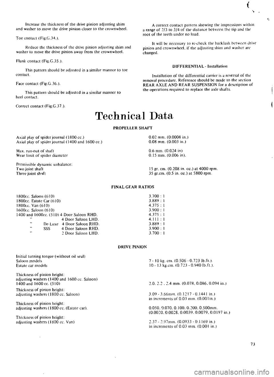
increase
the
thickness
of
the
drive
pinion
adjusting
shim
and
washer
to
move
the
drive
pinion
closer
to
the
crown
wheel
A
correct
contact
pattern
showing
the
impressioll
ithill
a
range
of
2
3
to
4
of
the
distance
bct
l
en
t
h
tip
lllU
till
root
of
the
teeth
under
no
load
Toe
contact
Fig
G
34
Rcdu
e
the
thickness
of
the
drive
pinion
adjusting
shim
and
washer
to
move
the
drive
pinion
away
from
the
crown
wheel
It
will
be
neCL
ssary
to
rc
check
the
backlash
bl
tW
Cl1
drivt
pinion
and
crown
wheel
if
the
adjusting
shim
1l1d
washer
arc
changed
Flank
contact
Fig
G
35
DIFFERENTIAL
Installation
This
pattern
should
be
adjusted
in
a
similar
manner
to
toe
contact
Face
contact
Fig
G
36
Installation
of
the
differential
carrier
is
J
reversal
of
the
removal
procedure
Reference
should
be
made
to
the
section
REAR
AXLE
AND
REAR
SUSPENSION
for
a
dl
saipIion
of
the
operations
required
to
replace
the
axle
shafts
This
pattern
should
be
adjusted
in
a
similar
manner
to
heel
contact
Correct
contact
Fig
G
37
Technical
Data
PROPELLER
SHAFT
Axial
play
of
spider
journal
0800
Axial
play
of
spider
journal
1400
and
1600
cc
0
Q2
mm
0
0008
in
0
08
mm
0
003
in
Max
run
out
of
shaft
Wear
limit
of
spider
diameter
0
6
mm
0
024
in
0
15
mm
0
006
in
Permissible
dynamic
unbalance
Two
joint
shaft
Three
joint
sh
lft
15
gr
em
0
208
in
oz
at
4000
rpm
35
gr
cm
0
5
in
oz
at
5800
rpm
FINAL
GEAR
RATIOS
1800cc
Saloon
6101
ISOOcc
Estate
Car
610
1800cc
Van
610
1600cl
SJloon
610
1400
and
1600cc
510
4
Door
Saloon
RHO
4
Door
Saloon
LHD
De
Lu
e
4
Door
Saloon
RHO
SSS
4
Door
Saloon
RHO
Door
Saloon
LHO
3700
3
889
4
375
3
900
4375
4111
3
889
3
900
3
700
DRIVE
PINION
InitiJI
turning
torque
without
oil
sea
Saloon
modds
Estate
CJr
models
7
10
kg
em
0
506
0
723Ib
ft
10
13
kg
em
0
723
0
940Ib
ft
Thickness
of
pinion
height
adjusting
washers
1400
and
1600
CC
Saloon
1400
and
1600cc
510
Thickncss
of
pinion
height
adjusting
washers
0800
cc
Saloon
0
4
mm
0
078
0
086
0
094
in
3
09
3
66mm
0
1
17
0
1441
in
in
increments
of
0
03
mm
0
00
I
in
Thickness
of
pinion
height
adjusting
washers
0800
n
Estate
car
0
050
0
070
0
100
0
200
0
500mm
0
0020
0
0028
0
0039
0
0079
0
0197
in
Thickness
of
pinion
height
adjusting
washers
1800
CL
Van
37
97111m
0
0933
0
I
69
in
in
increments
of
0
03
mm
0
00
I
in
73
Page 80 of 171
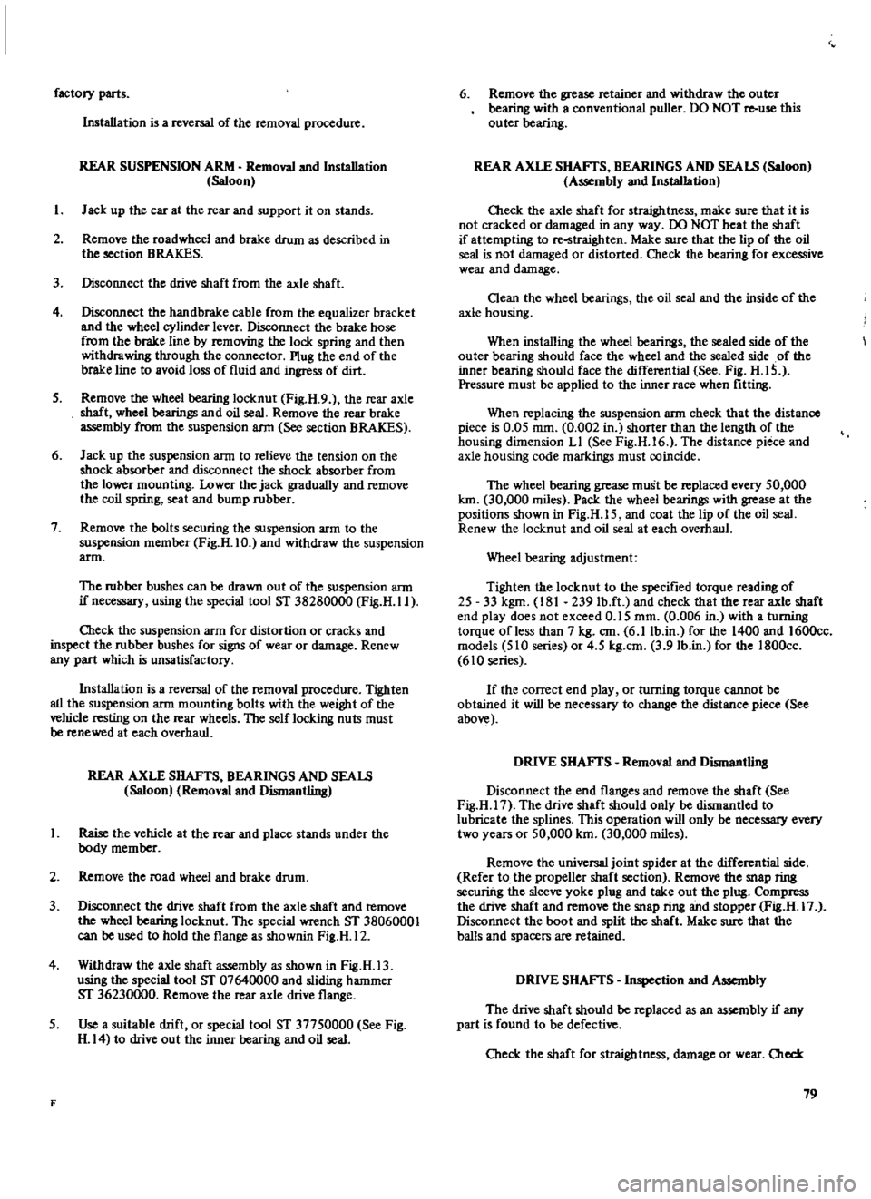
factory
parts
Installation
is
a
reversal
of
the
removal
procedure
REAR
SUSPENSION
ARM
Removal
and
Installation
Saloon
I
J
ad
up
the
car
at
the
rear
and
support
it
on
stands
2
Remove
the
road
wheel
and
brake
drum
as
described
in
the
section
BRAKES
3
Disconnect
the
drive
shaft
from
the
axle
shaft
4
Disconnect
the
handbrake
cable
from
the
equalizer
bracket
and
the
wheel
cylinder
lever
Disconnect
the
brake
hose
from
the
brake
line
by
removing
the
lock
spring
and
then
withdrawing
through
the
connector
Plug
the
end
of
the
brake
line
to
avoid
loss
of
fluid
and
ingress
of
dirt
5
Remove
the
wheel
bearing
locknut
Fig
H
9
the
rear
axle
shaft
wheel
bearings
and
oil
seal
Remove
the
rear
brake
assembly
from
the
suspension
ann
See
section
BRAKES
6
Jack
up
the
suspension
arm
to
relieve
the
tension
on
the
shock
absorber
and
disconnect
the
shock
absorber
from
the
lower
mounting
Lower
the
jack
gradually
and
remove
the
coil
spring
seat
and
bump
rubber
7
Remove
the
bolts
securing
the
suspension
arm
to
the
suspension
member
Fig
H
IO
and
withdraw
the
suspension
arm
The
rubber
bushes
can
be
drawn
out
of
the
suspension
arm
if
necessary
using
the
special
tool
ST
38280000
Fig
H
Il
O1eck
the
suspension
arm
for
distortion
or
cracks
and
inspect
the
rubber
bushes
for
signs
of
wear
or
damage
Renew
any
part
which
is
unsatisfactory
Installation
is
a
reversal
of
the
removal
procedure
Tighten
all
the
suspension
arm
mounting
bolts
with
the
weight
of
the
vehicle
resting
on
the
rear
wheels
The
self
locking
nuts
must
be
renewed
at
each
overhaul
REAR
AXLE
SHAFTS
BEARINGS
AND
SEALS
Saloon
Removal
and
Dismantling
I
Raise
the
vehicle
at
the
rear
and
place
stands
under
the
body
member
2
Remove
the
road
wheel
and
brake
drum
3
Disconnect
the
drive
shaft
from
the
axle
shaft
and
remove
the
wheel
bearing
locknut
The
special
wrench
ST
38060001
can
be
used
to
hold
the
flange
as
shownin
Fig
H
12
4
Withdraw
the
axle
shaft
assembly
as
shown
in
Fig
H
13
using
the
special
tool
ST
07640000
and
sliding
hammer
ST
36230000
Remove
the
rear
axle
drive
flange
5
Use
a
suitable
drift
or
special
tool
ST
37750000
See
Fig
H
14
to
drive
out
the
inner
bearing
and
oil
seal
F
6
Remove
the
grease
retainer
and
withdraw
the
outer
bearing
with
a
conventional
puller
DO
NOT
re
use
this
outer
bearing
REAR
AXLE
SHAFTS
BEARINGS
AND
SEALS
Saloon
Assembly
and
Installation
Oleck
the
axle
shaft
for
straightness
make
sure
that
it
is
not
cracked
or
damaged
in
any
way
00
NOT
heat
the
shaft
if
attempting
to
re
straighten
Make
sure
that
the
lip
of
the
oil
seal
is
not
damaged
or
distorted
Check
the
bearing
for
excessive
wear
and
damage
Oean
the
wheel
bearings
the
oil
seal
and
the
inside
of
the
axle
housing
When
installing
the
wheel
bearings
the
sealed
side
of
the
outer
bearing
should
face
the
wheel
and
the
sealed
side
of
the
inner
bearing
should
face
the
differential
See
Fig
H
IS
Pressure
must
be
applied
to
the
inner
race
when
fitting
When
replacing
the
suspension
arm
check
that
the
distance
piece
is
0
05
mm
0
002
in
shorter
than
the
length
of
the
housing
dimension
LI
See
Fig
H
16
The
distance
piece
and
axle
housing
code
markings
must
coincide
The
wheel
bearing
grease
must
be
replaced
every
50
000
km
30
000
miles
Pack
the
wheel
bearings
with
grease
at
the
positions
shown
in
Fig
H
IS
and
coat
the
lip
of
the
oil
seal
Renew
the
locknut
and
oil
seal
at
each
overhaul
Wheel
bearing
adjustment
Tighten
the
locknut
to
the
specified
torque
reading
of
25
33
kgm
181
239
lb
ft
and
check
that
the
rear
axle
shaft
end
play
does
not
exceed
0
15
mm
0
006
in
with
a
turning
torque
of
less
than
7
kg
em
6
11b
in
for
the
1400
and
1600cc
models
510
series
or
4
5
kg
em
3
91b
in
for
the
1800cc
610
series
If
the
correct
end
play
or
turning
torque
cannot
be
obtained
it
will
be
necessary
to
change
the
distance
piece
See
above
DRIVE
SHAFTS
Removal
and
Dismantlill8
Disconnect
the
end
flanges
and
remove
the
shaft
See
Fig
H
17
The
drive
shaft
should
only
be
dismantled
to
lubricate
the
splines
This
operation
will
only
be
necessary
every
two
years
or
50
000
km
30
000
miles
Remove
the
universal
joint
spider
at
the
differential
side
Refer
to
the
propeller
shaft
section
Remove
the
snap
ring
securiilg
the
sleeve
yoke
plug
and
take
out
the
plug
Compress
the
drive
shaft
and
remove
the
snap
ring
and
stopper
Fig
H
17
Disconnect
the
boot
and
split
the
shaft
Make
sure
that
the
balls
and
spacers
are
retained
DRIVE
SHAFTS
Inspection
and
Assembly
The
drive
shaft
should
be
replaced
as
an
assembly
if
any
part
is
found
to
be
defective
Check
the
shaft
for
straightness
damage
or
wear
Old
79
Page 92 of 171
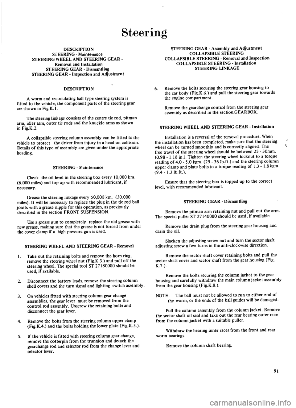
SteerIng
DEsn
IPTION
S
i
EERlNG
MaintenaDce
STEERING
WHEEL
AND
STEERING
GEAR
Removal
and
Installation
STEERING
GEAR
Dismantling
STEERING
GEAR
Inspection
and
Adjustment
DESCRIPTION
A
worm
and
recirculating
ball
type
steering
system
is
fitted
to
the
vehicle
the
component
parts
of
the
steering
gear
are
shown
in
Fig
K
I
The
steering
linkage
consists
of
the
centre
tie
rod
pitman
ann
idler
arm
outer
tie
rods
and
the
knuckle
arms
as
shown
in
Fig
K
2
A
collapsible
steering
column
assembly
can
be
fitted
to
the
vehicle
to
protect
the
driver
from
injury
in
a
head
on
collision
Details
of
this
type
of
assembly
are
given
under
the
appropriate
heading
STEERING
Maintenance
O1eck
the
oil
level
in
the
steering
box
every
10
000
km
6
000
miles
and
top
up
with
recommended
lubricant
if
necessary
Grease
the
steering
linkage
every
50
000
km
30
OOO
miles
It
will
be
necessary
to
replace
the
plug
in
the
tie
rod
ball
joints
with
a
grease
nipple
for
this
operation
as
previously
described
in
the
section
FRONT
SUSPENSION
Use
a
grease
gun
to
completely
replace
the
old
grease
with
new
grease
making
SUfe
that
the
grease
is
not
forced
from
under
the
cover
clamp
if
a
high
pressure
gun
is
used
STEERING
WHEEL
AND
STEERING
GEAR
Removal
1
Take
out
the
retaining
bolts
and
remove
the
horn
ring
remove
the
steering
wheel
nut
Fig
K
3
and
pull
off
the
steering
wheel
The
special
tool
ST
27180000
should
be
used
if
available
2
Disconnect
the
battery
leads
remove
the
steering
column
shell
covers
and
the
turn
signal
and
lighting
switch
assembly
3
On
vehicles
fitted
with
steering
column
gear
change
assemblies
the
gear
lever
must
be
removed
from
the
control
rod
assembly
Unscrew
the
retaining
boltg
and
disconnect
the
gear
lever
4
Remove
the
bolts
from
the
steering
column
upper
clamp
Fig
K
4
and
the
bolts
holding
the
lower
plate
Fig
K
5
5
If
the
vehicle
is
fitted
with
steering
column
gear
change
remove
the
cotterpin
from
the
trunnion
and
detach
the
gearchange
rod
and
selector
rod
from
the
change
lever
and
selector
lever
STEERING
GEAR
Assembly
and
Adjustment
COLLAPSIBLE
STEERING
COLLAPSIBLE
STEERING
Removal
and
Inspection
COLLAPSIBLE
STEERING
Installation
STEERING
LINKAGE
6
Remove
the
bolts
securing
the
steering
gear
housing
to
the
car
body
Fig
K
6
and
pull
the
steering
gear
towards
the
engine
compartment
Remove
the
gearchange
control
from
the
steering
gear
assembly
as
described
in
the
section
GEARBOX
STEERING
WHEEL
AND
STEERING
GEAR
Installation
Installation
is
a
reversal
of
the
removal
procedure
When
the
installation
has
been
completed
make
sure
that
the
steering
wheel
can
be
turned
smoothly
and
is
correctly
aligned
The
free
travel
of
the
steering
wheel
should
be
between
2S
30mm
0
9B
1
18
in
Tighten
the
steering
wheel
locknut
to
a
torque
reading
of
4
0
5
0
kgm
29
36Ib
ft
and
the
steering
column
upper
clamp
and
plate
bolts
to
a
torque
reading
of
1
3
1
8
kgm
94
1
3
Ib
ft
Ensure
that
the
steering
box
is
topped
up
to
the
correct
level
with
recommended
lubricant
STEERING
GEAR
Dismantling
Remove
the
pitman
arm
retaining
nut
and
pull
out
the
arm
The
special
puller
ST
27140000
should
be
used
if
available
Remove
the
drain
plug
from
the
steering
gear
housing
and
drain
the
oil
Slacken
the
adjusting
screw
nut
and
turn
the
sector
shaft
adjusting
screw
a
few
turns
in
the
anti
clockwise
direction
Remove
the
sector
shaft
cover
retaining
bolts
and
pull
the
sector
shaft
cover
and
sector
shaft
from
the
gear
housing
Fig
K
7
Remove
the
bolts
securing
the
column
jacket
to
the
gear
housing
and
carefully
withdraw
the
main
column
jacket
assembly
from
the
gear
housing
Fig
K
B
NOTE
The
ball
must
not
be
allowed
to
run
to
either
end
of
the
worm
or
the
ends
of
the
ball
guides
will
be
damaged
Pull
the
column
assembly
from
the
column
jacket
Remove
the
sector
shaft
oil
seal
and
take
out
the
rear
bearing
outer
race
from
the
column
jacket
with
a
suitable
puller
Withdraw
the
bearing
inner
races
from
the
front
and
fear
worm
bearings
Remove
the
column
shaft
bearing
91
Page 96 of 171
the
system
operates
smoothly
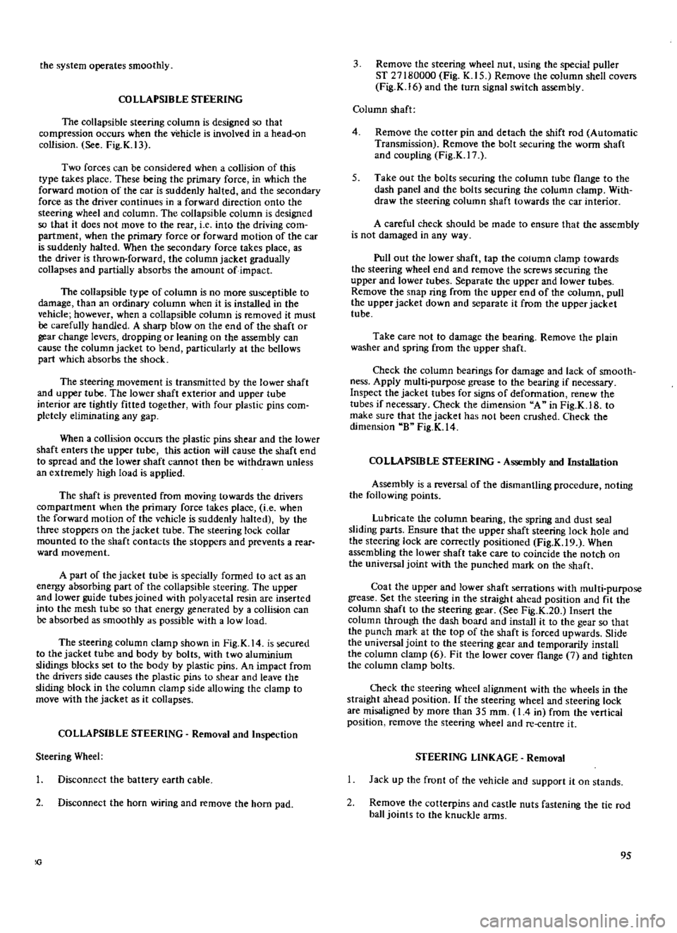
COLLAPSIBLE
STEERING
The
collapsible
steering
column
is
designed
so
that
compression
occurs
when
the
vehicle
is
involved
in
a
head
on
collision
See
Fig
K
13
Two
forces
can
be
considered
when
a
collision
of
this
type
takes
place
These
being
the
primary
force
in
which
the
forward
motion
of
the
car
is
suddenly
halted
and
the
secondary
force
as
the
driver
continues
in
a
forward
direction
onto
the
steering
wheel
and
column
The
collapsible
column
is
designed
so
that
it
does
not
move
to
the
rear
i
e
into
the
driving
com
partment
when
the
primary
force
or
forward
motion
of
the
car
is
suddenly
halted
When
the
secondary
force
takes
place
as
the
driver
is
thrown
forward
the
column
jacket
gradually
collapses
and
partially
absorbs
the
amount
of
impact
The
collapsible
type
of
column
is
no
more
susceptible
to
damage
than
an
ordinary
column
when
it
is
installed
in
the
vehicle
however
when
a
collapsible
column
is
removed
it
must
be
carefully
handled
A
sharp
blow
on
the
end
of
the
shaft
or
gear
change
levers
dropping
or
leaning
on
the
assembly
can
cause
the
column
jacket
to
bend
particularly
at
the
bellows
part
which
absorbs
the
shock
The
steering
movement
is
transmitted
by
the
lower
shaft
and
upper
tube
The
lower
shaft
exterior
and
upper
tube
interior
are
tightly
fitted
together
with
four
plastic
pins
com
pletely
eliminating
any
gap
When
a
collision
occurs
the
plastic
pins
shear
and
the
lower
shaft
enters
the
upper
tube
this
action
will
cause
the
shaft
end
to
spread
and
the
lower
shaft
cannot
then
be
withdrawn
unless
an
extremely
high
load
is
applied
The
shaft
is
prevented
from
moving
towards
the
drivers
compartment
when
the
primary
force
takes
place
i
e
when
the
forward
motion
of
the
vehicle
is
suddenly
halted
by
the
three
stoppers
on
the
jacket
tube
The
steering
lock
collar
mounted
to
the
shaft
contacts
the
stoppers
and
prevents
a
rear
ward
movement
A
part
of
the
jacket
tube
is
specially
formed
to
act
as
an
energy
absorbing
part
of
the
collapsible
steering
The
upper
and
lower
guide
tubes
joined
with
polyacetal
resin
are
inserted
into
the
mesh
tube
so
that
energy
generated
by
a
collision
can
be
absorbed
as
smoothly
as
possible
with
a
low
load
The
steering
column
clamp
shown
in
Fig
K
14
is
secured
to
the
jacket
tube
and
body
by
bolts
with
two
aluminium
slidings
blocks
set
to
the
body
by
plastic
pins
An
impact
from
the
drivers
side
causes
the
plastic
pins
to
shear
and
leave
the
sliding
block
in
the
column
clamp
side
allowing
the
clamp
to
move
with
the
jacket
as
it
collapses
COLLAPSffiLE
STEERING
Removal
and
Inspection
Steering
Wheel
I
Disconnect
the
battery
earth
cable
2
Disconnect
the
horn
wiring
and
remove
the
horn
pad
3
Remove
the
steering
wheel
nut
using
the
special
puller
ST
27180000
Eig
K
15
Remove
the
column
shell
covers
Fig
K
16
and
the
turn
signal
switch
assembly
Column
shaft
4
Remove
the
cotter
pin
and
detach
the
shift
rod
Automatic
Transmission
Remove
the
bolt
securing
the
worm
shaft
and
coupling
Fig
K
17
5
Take
out
the
bolts
securing
the
column
tube
flange
to
the
dash
panel
and
the
bolts
securing
the
column
clamp
With
draw
the
steering
column
shaft
towards
the
car
interior
A
careful
check
should
be
made
to
ensure
that
the
assembly
is
not
damaged
in
any
way
Pull
out
the
lower
shaft
tap
the
column
clamp
towards
the
steering
wheel
end
and
remove
the
screws
securing
the
upper
and
lower
tubes
Separate
the
upper
and
lower
tubes
Remove
the
snap
ring
from
the
upper
end
of
the
column
pull
the
upper
jacket
down
and
separate
it
from
the
upper
jacket
tube
Take
care
not
to
damage
the
bearing
Remove
the
plain
washer
and
spring
from
the
upper
shaft
Check
the
column
bearings
for
damage
and
lack
of
smooth
ness
Apply
multi
purpose
grease
to
the
bearing
if
necessary
Inspect
the
jacket
tubes
for
signs
of
deformation
renew
the
tubes
if
necessary
Check
the
dimension
A
in
Fig
K
1B
to
make
SUfe
that
the
jacket
has
not
been
crushed
Check
the
dimension
B
Fig
K
14
COLLAPSffiLE
STEERING
Assembly
and
Installation
Assembly
is
a
reversal
of
the
dismantling
procedure
noting
the
following
points
Lubricate
the
column
bearing
the
spring
and
dust
seal
sliding
parts
Ensure
that
the
upper
shaft
steering
lock
hole
and
the
steering
lock
are
correctly
positioned
Fig
K
19
When
assembling
the
lower
shaft
take
care
to
coincide
the
notch
on
the
universal
joint
with
the
punched
mark
on
the
shaft
Coat
the
upper
and
lower
shaft
serrations
with
multi
purpose
grease
Set
the
steering
in
the
straight
ahead
position
and
fit
the
column
shaft
to
the
steering
gear
See
Fig
K
20
Insert
the
column
through
the
dash
board
and
install
it
to
the
gear
so
that
the
punch
mark
at
the
top
of
the
shaft
is
forced
upwards
Slide
the
universal
joint
to
the
steering
gear
and
temporarily
install
the
column
clamp
6
Fit
the
lower
cover
flange
7
and
tighten
the
column
clamp
bolts
Check
the
steering
wheel
alignment
with
the
wheels
in
the
straight
ahead
position
If
the
steering
wheel
and
steering
lock
are
misaligned
by
more
than
35
mm
I
4
in
from
the
vertical
position
femove
the
steering
wheel
and
re
centre
it
STEERING
LINKAGE
Removal
Jack
up
the
front
of
the
vehicle
and
support
it
on
stands
2
Remove
the
cotterpins
and
castle
nuts
fastening
the
tie
rod
ball
joints
to
the
knuckle
arms
95
Page 118 of 171
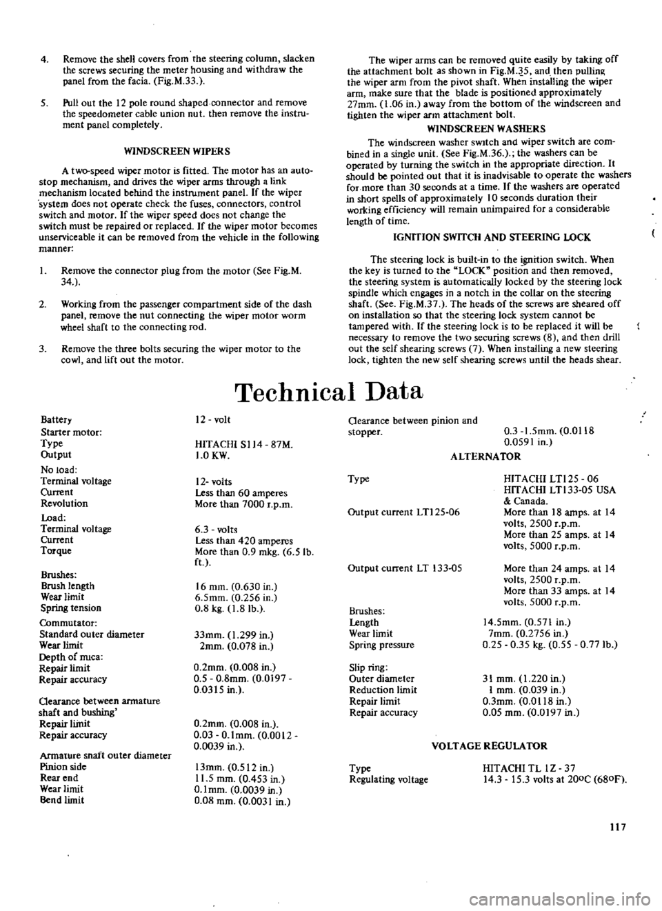
4
Remove
the
shell
covers
from
the
steering
column
slacken
the
screws
securing
the
meter
housing
and
withdraw
the
panel
from
the
facia
Fig
M
33
5
Pull
out
the
12
pole
round
shaped
connector
and
remove
the
speedometer
cable
union
nut
then
remove
the
instru
ment
panel
completely
WINDSCREEN
WIPERS
A
two
speed
wiper
motor
is
fitted
The
motor
has
an
auto
stop
mechanism
and
drives
the
wiper
arms
through
a
link
mechanism
located
behind
the
instrument
panel
If
the
wiper
system
does
not
operate
check
the
fuses
connectors
control
switch
and
motor
If
the
wiper
speed
does
not
change
the
switch
must
be
repaired
or
replaced
If
the
wiper
motor
becomes
unserviceable
it
can
be
removed
from
the
vehicle
in
the
fOllowing
manner
I
Remove
the
connector
plug
from
the
motor
See
Fig
M
34
2
Working
from
the
passenger
compartment
side
of
the
dash
panel
remove
the
nut
connecting
the
wiper
motor
worm
wheel
shaft
to
the
connecting
rod
3
Remove
the
three
bolts
securing
the
wiper
motor
to
the
cowl
and
lift
out
the
motor
Battery
Starter
motor
Type
Output
No
load
Terminal
voltage
Current
Revolution
Load
Terminal
voltage
Current
Torque
Brushes
Brush
length
Wear
limit
Spring
tension
Commutator
Standard
outer
diameter
Wear
limit
Depth
of
nuca
Repair
limit
Repair
accuracy
Qearance
between
armature
shaft
and
bushing
Repair
liinit
Repair
accuracy
Armature
shaft
ou
ter
diameter
Pinion
side
Rear
end
Wear
limit
Bend
limit
The
wiper
arms
can
be
removed
quite
easily
by
taking
off
the
attachment
bolt
as
shown
in
Fig
M
J
5
and
then
pullin
the
wiper
arm
from
the
pivot
shaft
When
installing
the
wiper
arm
make
sure
that
the
blade
is
positioned
approximately
27mm
1
06
in
away
from
the
bottom
of
the
windscreen
and
tighten
the
wiper
arm
attachment
bolt
WINDSCREEN
WASHERS
The
windscreen
washer
SWItch
and
wiper
switch
are
com
bined
in
a
single
unit
See
Fig
M
36
the
washers
can
be
operated
by
turning
the
switch
in
the
appropriate
direction
It
should
be
pointed
out
that
it
is
inadvisable
to
operate
the
washers
for
more
than
30
seconds
at
a
time
If
the
washers
are
operated
in
short
spells
of
approximately
10
seconds
duration
their
working
efficiency
will
remain
unimpaired
for
a
considerable
length
of
time
IGNITION
SWITCH
AND
STEERING
LOCK
The
steering
lock
is
built
in
to
the
goition
switch
When
the
key
is
turned
to
the
LOCK
position
and
then
removed
the
steering
system
is
automatically
locked
by
the
steering
lock
spindle
which
engages
in
a
notch
in
the
collar
on
the
steering
shaft
See
Fig
M
37
The
heads
of
the
screws
are
sheared
off
on
installation
so
that
the
steering
lock
system
cannot
be
tampered
with
If
the
steering
lock
is
to
be
replaced
it
will
be
necessary
to
remove
the
two
securing
screws
8
and
then
drill
out
the
self
shearing
screws
7
When
installing
a
new
steering
lock
tighten
the
new
self
shearing
screws
until
the
heads
shear
TechnICal
Data
12
volt
HITACHI
S114
87M
1
0KW
12
volts
Less
than
60
amperes
More
than
7000
r
p
m
6
3
volts
Less
than
420
amperes
More
than
0
9
mkg
6
5
lb
ft
16
mm
0
630
in
6
5mm
0
256
in
0
8
kg
1
8
lb
33mm
1
299
in
2mm
0
078
in
0
2mm
0
008
in
0
5
0
8mm
0
0197
0
0315
in
0
2mm
0
008
in
0
03
O
lmm
0
0012
0
0039
in
13mm
0
512
in
11
5
mm
0
453
in
O
lmm
0
0039
in
0
08
mm
0
0031
in
Oearance
between
pinion
and
stopper
0
3
1
5mm
0
0118
0
0591
in
ALTERNATOR
Type
HITACHI
LTl25
06
HITACHI
LTl33
05
USA
Canada
More
than
18
amps
at
14
volts
2500
r
p
m
More
than
25
amps
at
14
volts
5000
r
p
m
Output
current
LTl25
06
Output
current
LT
133
05
More
than
24
amps
at
14
volts
2500
r
p
m
More
than
33
amps
at
14
volts
5000
r
p
m
Brushes
Lengtb
Wear
limit
Spring
pressure
14
5mm
0
571
In
7mm
0
2756
in
0
25
0
35
kg
0
55
0
771b
Slip
ring
Outer
diameter
Reduction
limit
Repair
limit
Repair
accuracy
31
mm
1
220
in
I
mm
0
039
in
O
3mm
0
0118
in
0
05
mm
0
0197
in
VOLTAGE
REGULATOR
Type
Regulating
voltage
HITACHI
TL
lZ
37
14
3
15
3
volts
at
200C
680F
117
Page 130 of 171
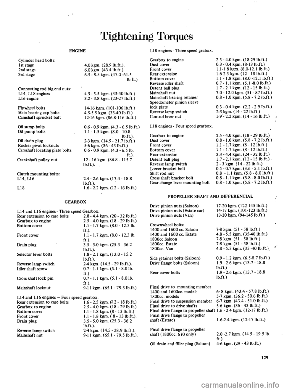
TIghtenIng
Torques
LIB
engines
Three
speed
geabox
ENGINE
2
5
4
0
kgm
18
29
Ib
ft
0
3
0
4
kgm
8
13
IbJI
Ll
1
8
kgm
8
0
12
llbJt
1
6
2
5
kgm
12
18Ib
ft
I
I
1
8
kgm
8
0
12
llbJt
0
7
I
I
kgm
5
1
8
0
IbJt
17
2
lkgm
l2
15IbJI
7
0
12
0
kgm
51
87IbJI
0
8
1
0
kgm
5
8
7
2
IbJI
0
3
0
4
kgm
2
2
2
9Ib
ft
2
3
kgm
14
22IbJI
J
9
2
2
kgm
14
16IbJI
Gearbox
to
engine
Dust
cover
Front
cover
Rear
extension
Bottom
cover
Reverse
idler
shaft
Detent
ball
plug
Mainshaft
nut
Mainshaft
bearing
retainer
Speedometer
pinion
sleeve
lock
plate
Reverse
lamp
switch
Control
lever
nut
Cylinder
head
bolts
1st
stage
2nd
stage
3rd
slage
4
0
kgm
28
9Ib
ft
6
0
kgm
43
4lb
ft
6
5
8
5
kgm
47
0
61
5
Ib
ft
Connecting
rod
big
end
nuts
Ll4
Ll8
engines
Ll6
engine
Flywheel
bolls
Main
bearing
cap
bolts
Camshaft
sprocket
bolt
4
5
5
5
kgm
33
40
Ib
fl
3
2
3
8
kgm
23
27
lb
ft
14
16
kgm
l01
106Ib
ft
4
5
5
5
kgm
33
40Ib
ft
12
16
kgm
86
8
116IbJt
0
6
0
9
kgm
4
3
6
5IbJt
I
I
1
5
kgm
8
0
10
8
Ib
fl
2
3
kgm
14
5
21
7Ib
ft
5
6
kgm
36
43
Ib
ft
0
6
0
9
kgm
4
3
6
5
Ib
ft
12
16kgm
86
8
115
7
IbJt
LIB
engines
Four
speed
gearbox
Oil
sump
bolts
Oil
pump
bolts
Oil
drain
plug
Rocker
pivot
locknuts
Camshaft
locating
plate
bolts
2
5
4
0
kgm
18
29
IbJt
0
8
1
0
kgm
5
8
7
2Ib
ft
Ll
l
7kgm
8
12IbJt
Ll
I
7kgm
8
12Ib
ft
3
3
44
kgm
24
32IbJI
1
7
2
1
kgm
12
15
IbJt
2
3
kgm
14
22Ib
ft
0
5
0
7
kgm
3
6
5
IlbJI
0
8
I
I
kgm
5
8
8
0Ib
ft
0
8
Ll
kgm
5
8
8
01b
ft
0
8
1
0
kgm
5
8
7
2Ib
ft
Gearbox
to
engine
Dust
cover
Front
cover
Bottom
cover
Rear
extension
Detent
ball
plug
Reverse
lamp
switch
Lower
bracket
bolt
Shift
rod
nut
Cross
shaft
bracket
bolt
Gear
change
lever
mounting
bolt
Crankshaft
pulley
nut
Outch
mounting
bolts
L14
Ll6
Ll8
2
4
2
6kgm
174
18
8
Ib
ft
1
6
2
2
kgm
12
16Ib
fl
PROPELLER
SHAFf
AND
DIFFERENTIAL
GEARBOX
17
20kgm
l22
145IbJI
14
17
kgm
101
123Ib
ft
13
20
kgm
94
145Ib
fI
Drive
pinion
nuts
Saloon
Drive
pinion
nuts
Estate
car
Drive
pinion
nuts
Van
Ll4
and
L16
engines
Three
speed
Gearbox
Rear
extension
to
case
bolts
2
8
4
4
kgm
20
32lb
ft
Gearbox
10
engine
2
5
4
0
kgm
18
29Ib
fI
Bnttom
cover
L1
1
7
kgm
8
0
12
3
lb
ft
Ll
1
7
kgm
8
0
12
3
lb
fl
3
5
5
0
kgm
25
3
36
2
Ib
ft
1
8
2
1
kgm
13
0
15
2
Ib
ft
2
4
kgm
14
5
29
Ib
ft
0
7
L1
kgm
5
1
8
0
lb
ft
0
7
Ll
kgm
5
1
8
0
lb
fl
9
11
kgm
65
1
79
51b
ft
Crown
wheel
bolts
1400
and
1600
cc
Saloon
1400
and
1600
cc
Eslale
1800ce
Saloon
I800cc
Estate
1800cc
Van
7
8
kgm
51
58Ib
ft
4
8
5
5
kgm
35
40
Ib
ft
7
8
kgm
51
58Ib
ft
7
8
kgm
51
58Ib
ft
4
8
5
5
kgm
35
40
Ib
ft
0
9
1
2
kgm
6
5
8
7Ib
ft
1
9
2
6
kgm
13
7
18
8
IbJI
1
9
2
6
kgm
13
7
18
8
Ib
f
Front
cover
Drain
plug
Selector
lever
bolts
Side
retainer
bolts
Saloon
Drive
flange
bolts
Saloon
Reverse
lamp
switch
Idler
shaft
screw
Rear
cover
bolts
Cross
shaft
lock
pin
Final
drive
to
mounting
member
1400
and
1600cc
models
6
8
kgm
43
4
57
8IbJI
1800cc
models
5
7
kgm
36
2
50
6Ib
fI
Final
drive
to
suspension
member
6
7
kgm
43
4
51
0
Ib
ft
Final
drive
to
drive
shafls
5
6
kgm
36
431b
ft
Final
drive
flange
to
propeller
shaft
1
6
2
4
kgm
12
17
Ib
ft
Final
drive
flange
to
propeller
shaft
Eslale
1
6
2
4
kgm
l2
17Ib
ft
Mainshafl
locknut
Ll4
and
L16
engines
Four
speed
gearbox
Rearexlension
to
case
bolts
1
6
2
5
kgm
12
18Ib
ft
Gearbox
to
engine
2
5
4
0
kgm
18
29Ib
ft
Bottnm
cnver
L1
1
8
kgm
8
13
Ib
ft
Fronl
cover
L1
1
8
kgm
8
13
IbJI
Drain
plug
3
5
5
0
kgm
25
3
36
2
Ib
f
2
4
kgm
14
5
28
9IbJt
9
11
kgm
65
1
79
5Ib
ft
Final
drive
flange
to
propeller
shaft
l800cc
610
only
Reverse
lamp
switch
Mainshaft
nut
2
0
2
7
kgm
14
5
19
5
lb
ft
4
6
kgm
29
43
Ib
ft
Oil
drain
and
flller
plug
Saloon
129