lock DATSUN 610 1969 Manual PDF
[x] Cancel search | Manufacturer: DATSUN, Model Year: 1969, Model line: 610, Model: DATSUN 610 1969Pages: 171, PDF Size: 10.63 MB
Page 148 of 171

Fan
coupling
Pulley
ratio
fan
and
water
pump
Tuning
data
Basic
timing
Idling
speed
Distributor
dwell
angle
Spark
plug
gap
Choke
setting
CO
percent
setting
Fan
rpm
water
pump
rpm
3
300
4
000
120
103
Ll71
50
A
T
D
C
700
rpm
650
rpm
automatic
490
550
at
0
02
in
breaker
gap
0
8IJ
0
90
mm
0
03
I
5
0
0355
in
Manual
6
0
I
0
5
air
supply
hose
disconnected
Air
pump
drive
belt
tensioning
Permissible
slackness
of
8
0
12
0
mm
0
3
15
0
4
72
in
under
a
load
of7
1O
kg
1
54
2
20
lb
IGNITION
SYSTEM
DISTRIBUTOR
Type
Firing
order
Rotation
Igntion
timing
Without
emission
control
With
emission
control
Dwell
angle
Condenser
capacity
Advance
characteristics
D416
57
distributor
Hitachi
D416
57
Hitachi
D423
53
with
emission
control
system
134
2
Anti
clockwise
80
B
T
D
C
at
600
rpm
50
A
T
D
C
at
600
r
p
m
49
to
55
degreos
0
20
0
24
1
F
Centrifugal
Start
Maximum
degree
r
p
m
Vacuum
Start
Maximum
degree
r
p
m
Advance
characteristics
D423
53
distributor
Centrifugal
Start
Maximum
degree
r
p
m
Vacuum
Start
Maximum
degree
r
p
m
IGNITION
COIL
Type
Primary
voltage
Spark
gap
Primary
resistance
Secondary
resistance
SPARKING
PLUGS
Type
Gap
Fuel
Systenl
DESCRIPTION
FUEL
PUMP
Testing
FUEL
PUMP
Removing
and
Dismantling
CARBURETTOR
Idling
adjustment
FUEL
LEVEL
Adjusting
STARTING
INTERLOCK
VALVE
OPENING
THROTTLE
VALVE
INTERLOCK
OPENING
CARBURETIOR
Removing
and
Dismantling
DESCRIPTION
A
dual
barrel
down
draught
type
carburettor
is
fitted
to
vehicles
with
the
G
18
engine
A
Stromberg
type
D3034C
carburet
tor
is
installed
on
engines
with
exhaust
emission
controL
and
a
Solex
type
DAK340
carburettor
on
engines
not
equipped
with
this
type
of
system
Both
types
of
carburettors
incorporate
a
550
r
p
m
01
50
at
I
400
16
50
at
2
800
80
mmHg
6
50
at
200
r
p
m
475
r
p
m
01
50
at
1
000
23
50
at
2
600
80
mm
Hg
30
at
120
r
p
m
go
at
400
r
p
m
Hanshin
HM
12F
or
HP5
I
OE
with
emission
control
system
12
volts
more
than
6
mm
0
2362
in
3
8
ohms
at
200C
I
1
2
I
6
8
ohms
at
200
C
NGK
BP
6E
0
7
0
8
mm
0
028
0
031
in
or
0
80
9
mm
0
031
0
035
in
with
emission
control
system
primary
system
for
normal
running
and
a
secondary
system
for
full
load
running
a
float
assembly
which
supplies
fuel
to
both
primary
and
secondary
systems
a
starting
mechanism
and
accelerator
pump
which
provides
a
richer
mixture
on
accelera
tion
SI7
Page 150 of 171
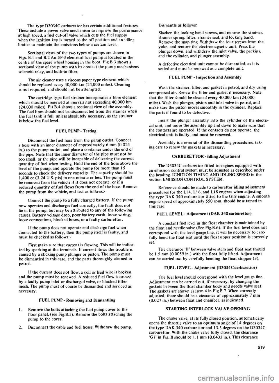
The
type
D3034C
carburettor
has
certain
additional
features
These
include
a
power
valve
mechanism
to
improve
the
performance
at
high
speed
a
fuel
cut
off
valve
which
cuts
the
fuel
supply
when
the
ignition
key
is
turned
to
the
off
position
and
an
idling
limiter
to
maintain
the
emissions
below
a
certain
level
Sectional
views
of
the
two
types
of
pumps
are
shown
in
Figs
8
1
and
B
2
An
EP
3
electrical
fuel
pump
is
located
in
the
centre
of
the
spare
wheel
housing
in
the
boot
Fig
B
3
shows
a
sectional
view
of
the
pump
with
its
contact
the
pump
mechanisms
solenoid
relay
and
built
in
filter
The
air
cleaner
uses
a
viscous
paper
type
element
which
should
be
replaced
every
40
000
km
24
000
miles
Cleaning
is
not
required
and
should
not
be
attempted
The
cartridge
type
fuel
strainer
incorporates
a
fibre
clement
which
should
be
renewed
at
inervals
not
exceeding
40
000
km
24
000
miles
Fit
B
4
shows
a
sectional
view
of
the
assembly
The
fuel
lines
should
not
be
disconnected
from
the
strainer
when
the
fuel
tank
is
full
unless
absolutely
necessary
as
the
strainer
is
below
the
fuel
level
FUEL
PUMP
Testing
Disconnect
the
fuel
hose
from
the
pump
outlet
Connect
a
hose
with
an
inner
diameter
of
approximately
6
mm
0
024
in
to
the
pump
outlet
and
place
a
container
under
the
end
of
the
pipe
Note
that
the
inner
diameter
of
the
pipe
must
not
be
too
small
or
the
pipe
will
be
incapable
of
delivering
the
correct
quantity
of
fuel
when
testing
Hold
the
end
of
the
hose
above
the
level
of
the
pump
and
operate
the
pump
for
more
than
IS
seconds
to
check
the
delivery
capacity
The
capacity
should
be
I
400
cc
3
24
U
S
pts
in
one
minute
or
less
The
pump
must
be
removed
from
the
vehicle
if
it
does
not
operate
or
if
a
reduced
quantity
of
fuel
flows
from
the
end
of
the
hose
Remove
the
pump
from
the
vehicle
and
test
as
follows
Connect
the
pump
to
a
fully
charged
battery
If
the
pump
now
operates
and
discharges
fuel
correctly
the
fault
does
not
lie
in
the
pump
but
may
be
attributed
to
any
of
the
following
causes
Battery
voltage
drop
poor
battery
earth
loose
wiring
loose
connections
blocked
hoses
or
a
faulty
carburettor
If
the
pump
does
not
operate
and
discharge
fuel
when
connected
to
the
battery
then
the
pump
itself
is
faulty
and
must
be
checked
as
follows
First
make
sure
that
current
is
flowing
This
will
be
indica
ted
by
sparking
at
the
tenninals
If
current
flows
the
trouble
is
caused
by
a
sticking
pump
plunger
or
piston
The
pump
must
be
dismantled
in
this
case
and
the
parts
thoroughly
cleaned
in
petrol
If
the
current
does
not
flow
a
coil
or
lead
wire
is
broken
and
the
pump
must
be
renewed
A
reduced
fuel
flow
is
caused
by
a
faulty
pump
inlet
or
discharged
valve
or
blocked
filter
mesh
The
pump
must
of
course
be
dismantled
and
serviced
as
necessary
FUEL
PUMP
Removing
and
Dismantling
Remove
the
bolts
attaching
the
fuel
pump
cover
to
the
floor
panel
see
Fig
B
S
Remove
the
bolts
attaching
the
pump
to
the
cover
2
Disconnect
the
cable
and
fuel
hoses
Withdraw
the
pump
Dismantle
as
follows
Slacken
the
locking
band
screws
and
remove
the
strainer
strainer
spring
filter
strainer
seal
and
locking
band
Remove
the
snap
ring
Withdraw
the
four
screws
from
the
yoke
and
remove
the
electromagnetic
ulJ
it
Press
the
plunger
down
and
withdraw
the
inlet
vaive
the
packing
and
the
cylinder
and
plunger
assembly
A
defective
eledrical
unit
cannot
be
dismantled
as
it
is
sealed
and
must
be
renewed
as
a
complete
unit
FUEL
PUMP
Inspection
and
Assembly
Wash
the
strainer
filter
and
gasket
in
petrol
and
dry
using
compressed
air
Renew
the
filter
and
gasket
if
necessary
Note
that
the
filter
should
be
cleaned
every
40
000
km
24
000
miles
Wash
the
plunger
piston
and
inlet
valve
in
petrol
and
make
sure
the
piston
moves
smoothly
in
the
cylinder
Replace
the
parts
if
found
to
be
defective
Insert
the
plunger
assembly
into
the
cylinder
of
the
electri
cal
unit
and
move
the
assembly
up
and
down
to
make
sure
tha
t
the
contacts
are
operated
If
the
contacts
do
not
operate
the
electrical
unit
is
faulty
and
must
be
renewed
Assembly
is
a
reversal
of
the
dismantling
procedures
tak
ing
care
to
renew
the
gaskets
as
necessary
CARBURETIOR
Idling
Adjustment
The
D3034C
carburettor
fitted
to
engines
equipped
with
an
emission
control
system
must
be
adjusted
as
described
under
the
heading
IGNITION
TIMING
AND
IDLING
SPEED
in
the
section
EMISSION
CONTROL
SYSTEM
Reference
should
be
made
to
carburettor
idling
adjustment
procedures
for
the
L14
L16
and
LI8
engines
when
adjusting
the
type
DAK
340
carburettor
fitted
to
the
G
18
engine
A
smooth
engine
speed
of
approximately
550
rpm
should
be
attained
in
this
case
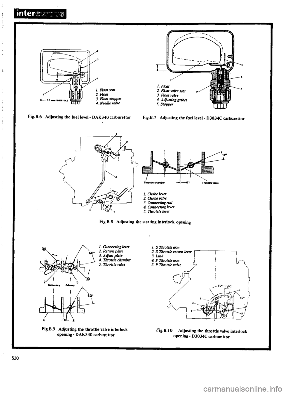
FUEL
lEVEL
Adjustment
DAK
340earburettor
A
constant
fuellevcl
in
the
float
chamber
is
maintained
by
the
float
and
needle
valve
See
Fig
8
6
If
the
fuel
level
does
not
correspond
with
the
level
gauge
line
it
will
be
necessary
to
care
fully
bend
the
float
seat
until
the
float
upper
position
is
correctly
set
The
clearance
H
between
valve
stem
and
float
seat
should
be
I
5
mm
0
0059
in
with
the
float
fully
lifted
Adjustment
can
be
carried
out
by
carefully
bending
the
float
stopper
3
FUEL
lEVEL
Adjustment
D3034Ccarburettnr
The
fuel
level
should
correspond
with
the
level
gauge
line
Adjustment
can
be
carried
out
if
necessary
by
changing
the
gaskets
between
the
float
chamber
body
and
needle
valve
seat
The
gaskets
are
shown
as
item
4
in
Fig
B
7
When
correctly
adjusted
there
should
be
a
clearance
of
approximately
7
mm
0
027
in
between
float
and
chamber
as
indicated
STARTING
INTERLOCK
VALVE
OPENING
The
choke
valve
at
its
fully
closed
position
automatically
opens
the
throttle
valve
to
an
optimum
angle
of
14
degrees
on
the
type
DAK
340
carburettor
and
13
5
degrees
on
the
D3034C
carburettor
With
the
choke
valve
fully
closed
the
clearance
G
I
in
Fig
8
should
be
1
I
mm
0
0433
in
This
clearance
S19
Page 151 of 171
Onter
1
2
I
J
I
I
I
r
f
r
1
Float
SelllC
2
F10aI
3
Ffotzt
toppt
T
4
Nudk
m
1
F10at
2
Float
WJlve
ltat
3
Float
valJ1e
4
AcJiwtiflK
tpsket
5
Stopper
Fig
B
6
Adjusting
the
fuel
level
DAK340
C3tbutettor
Fig
B
7
Adjusting
the
fuel
level
D3034C
carburettor
1
11
J
Xi
I
tf
J
t
I
3
J
I
J
Th
1
Choke
mr
r
2
Otoke
m
LuL
3
Conn
ting
rod
4
Connectinlla
o
5
TIuottle
lever
Fig
B
S
Adjusting
the
starting
interlock
opening
6
O
1
Co1UJeCdrlK
lev
2
Rerum
plate
3
Adiust
pWe
4
17rrottle
clrzmber
5
Throttle
valve
1
S
Throttle
arm
2
S
Throttle
ntum
lever
3
Link
4
P1lIrortle
tml
5
P
1lIro
lle
valve
l
I
4
J
L
5
iF
l
1
L
Fig
B
9
Adjusting
the
throttle
valve
interlock
opening
OAK340
carburettor
Fig
B
lO
Adjusting
tbe
throttle
valve
interlock
opening
D3034C
carburettor
520
Page 152 of 171
between
primary
throttle
valve
and
the
wall
of
the
throttle
chamber
can
be
adjusted
if
necessary
by
carefully
bending
the
choke
connecting
rod
3
THROTILE
VALVE
INTERLOCK
OPENING
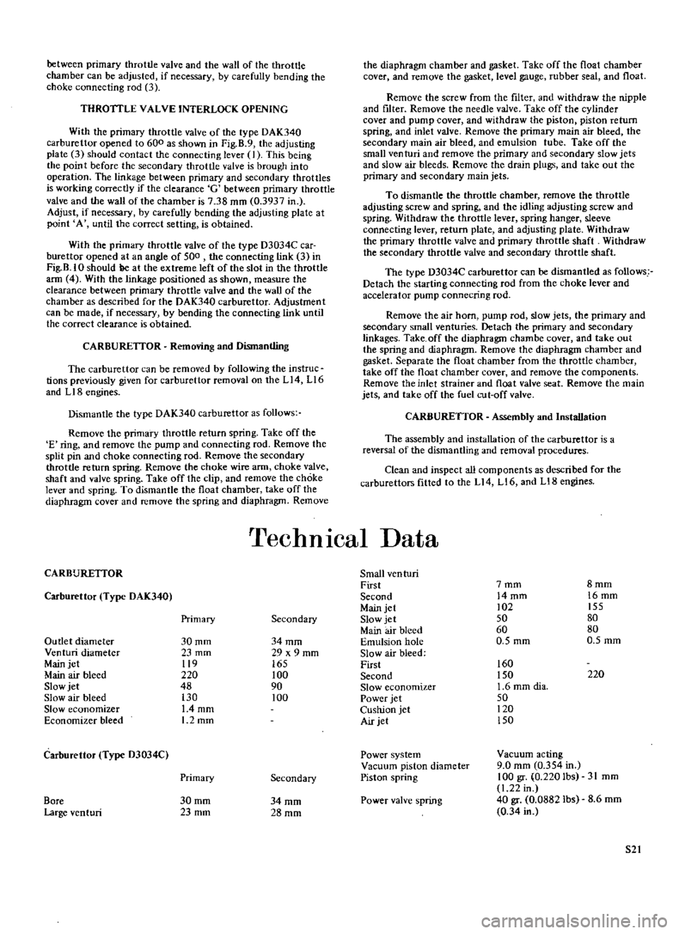
With
the
primary
throttle
valve
of
the
type
DAK340
carburettor
opened
to
600
as
shown
in
Fig
B
9
the
adjusting
plate
3
should
contact
the
connecting
lever
J
This
being
the
point
before
the
secondary
throttle
valve
is
brough
into
operation
The
linkage
between
primary
and
secondary
throttles
is
working
correctly
if
the
clearance
G
between
primary
throttle
valve
and
the
wall
of
the
chamber
is
738
mm
0
3937
in
Adjust
if
necessary
by
carefully
bending
the
adjusting
plate
at
point
A
until
the
correct
setting
is
obtained
With
the
primary
throttle
valve
of
the
type
D3034C
car
burettor
opened
at
an
angle
of
500
the
connecting
link
3
in
Fig
B
IO
should
ge
at
the
extreme
left
of
the
slot
in
the
throttle
ann
4
With
the
linkage
positioned
as
shown
measure
the
clearance
between
primary
throttle
valve
and
the
wall
of
the
chamber
as
described
for
the
DAK340
carburettor
Adjustment
can
be
made
if
necessary
by
bending
the
connecting
link
until
the
correct
clearance
is
obtained
CARBURElTOR
Removing
and
Dismantling
The
carburettor
can
be
removed
by
following
the
instruc
tions
previously
given
for
carburettor
removal
on
the
Ll4
L16
and
LIB
engines
Dismantle
the
type
DAK340
carburettor
as
follows
Remove
the
primary
throttle
return
spring
Take
off
the
E
ring
and
remove
the
pump
and
connecting
rod
Remove
the
split
pin
and
choke
connecting
rod
Remove
the
secondary
throttle
return
spring
Remove
the
choke
wire
arm
choke
valve
shaft
and
valve
spring
Take
off
the
clip
and
remove
the
choke
lever
and
spring
To
dismantle
the
float
chamber
take
off
the
diaphragm
cover
and
remove
the
spring
and
diaphragm
Remove
the
diaphragm
chamber
and
gasket
Take
off
the
float
chamber
cover
and
remove
the
gasket
level
gauge
rubber
seal
and
float
Remove
the
screw
from
the
filter
and
withdraw
the
nipple
and
filter
Remove
the
needle
valve
Take
off
the
cylinder
cover
and
pump
cover
and
withdraw
the
piston
piston
return
spring
and
inlet
valve
Remove
the
primary
main
air
bleed
the
secondary
main
air
bleed
and
emulsion
tube
Take
off
the
small
venturi
and
remove
the
primary
and
secondary
slow
jets
and
slow
air
bleeds
Remove
the
drain
plugs
and
take
out
the
primary
and
secondary
main
jets
To
dismantle
the
throttle
chamber
remove
the
throttle
adjusting
screw
and
spring
and
the
idling
adjusting
screw
and
spring
Withdraw
the
throttle
lever
spring
hanger
sleeve
connecting
lever
return
plate
and
adjusting
plate
Withdraw
the
primary
throttle
valve
and
primary
throttle
shaft
Withdraw
the
secondary
throttle
valve
and
secondary
throttle
shaft
The
type
D3034C
carburettor
can
be
dismantled
as
follows
Detach
the
starting
connecting
rod
from
the
choke
lever
and
accelerator
pump
connecting
rod
Remove
the
air
horn
pump
rod
slow
jets
the
primary
and
secondary
small
venturies
Detach
the
primary
and
secondary
linkages
Take
off
the
diaphragm
chambe
cover
and
take
out
the
spring
and
diaphragm
Remove
the
diaphragm
chamber
and
gasket
Separate
the
float
chamber
from
the
throttle
chamber
take
off
the
float
chamber
cover
and
remove
the
components
Remove
the
inlet
strainer
and
float
valve
seat
Remove
the
main
jets
and
take
off
the
fuel
cut
off
valve
CARBURETTOR
Assembly
and
Installation
The
assembly
and
installation
of
the
carburettor
is
a
reversal
of
the
dismantling
and
removal
procedures
Clean
and
inspect
all
components
as
described
for
the
carburettors
fitted
to
the
Ll4
Ll6
and
LI8
engines
TechnIcal
Data
CARBURETIOR
Small
ven
turi
First
7mm
8mm
Carburettor
Type
DAK340
Second
14mm
16mm
Main
jet
02
155
Primary
Secondary
Slow
jet
50
80
Main
air
bleed
60
80
Outlet
diameter
30mm
34mm
Emulsion
hole
0
5
mm
O
5mm
Venturi
diameter
23
mm
29
x
9
mm
Slow
air
bleed
Main
jet
119
165
First
160
Main
air
bleed
220
100
Second
150
220
Slow
jet
48
90
Slow
economizer
1
6
mm
dia
Slow
air
bleed
130
100
Power
jet
50
Slow
economizer
L4mm
Cushion
jet
120
Economizer
bleed
1
2mm
Air
jet
150
Carburettor
Type
D3034C
Power
system
Vacllum
acting
Vacuum
piston
diameter
9
0
mm
0
354
in
Primary
Secondary
Piston
spring
100
gr
0
220
Ibs
31
mm
1
22
in
Bore
30mm
34mm
Power
valve
spring
40
gr
0
0882
lbs
8
6mm
Large
venturi
23mm
28mm
0
34
in
52
Page 156 of 171
Remove
the
road
wheel
and
disconnect
the
brake
hose
at
the
connector
as
shown
in
Fig
C
4
of
this
section
Remove
the
brake
calliper
assembly
and
hub
cap
Withdraw
the
cotter
pin
and
remove
the
wheel
bearing
locknut
Remove
the
wheel
bearing
washer
and
take
off
the
hub
and
brake
disc
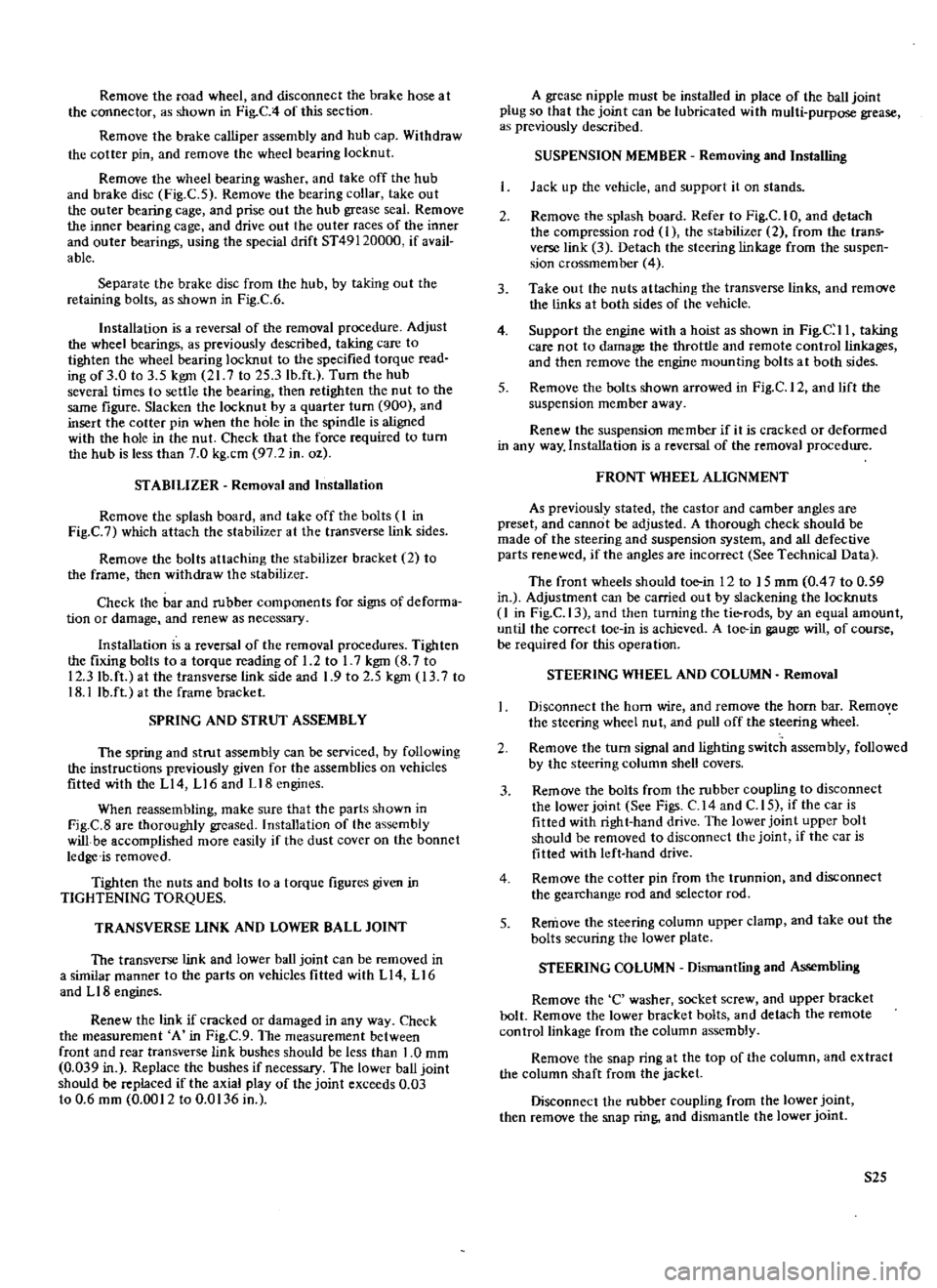
Fig
C
5
Remove
the
bearing
collar
take
out
the
outer
bearing
cage
and
prise
out
the
hub
grease
seal
Remove
the
inner
bearing
cage
and
drive
out
the
outer
races
of
the
inner
and
outer
bearings
using
the
special
drift
ST49120000
if
avail
able
Separate
the
brake
disc
from
the
hub
by
taking
out
the
retaining
bolts
as
shown
in
Fig
C
6
Installation
is
a
reversal
of
the
removal
procedure
Adjust
the
wheel
bearings
as
previously
described
taking
care
to
tighten
the
wheel
bearing
locknut
to
the
specified
torque
read
ing
of
3
0
to
3
5
kgm
21
7
to
25
3lb
ft
Turn
the
hub
several
times
to
settle
the
bearing
then
retighten
the
nut
to
the
same
figure
Slacken
the
locknut
by
a
quarter
turn
900
and
insert
the
cotter
pin
when
the
hole
in
the
spindle
is
aligned
with
the
hole
in
the
nut
Check
that
the
force
required
to
turn
the
hub
is
less
than
7
0
kg
cm
97
2
in
oz
STABILIZER
Removal
and
Installation
Remove
the
splash
board
and
take
off
the
bolts
I
in
Fig
C
7
which
attach
the
stabilizer
at
the
transverse
link
sides
Remove
the
bolts
attaching
the
stabilizer
bracket
2
to
the
frame
then
withdraw
the
stabilizer
Check
the
bar
and
rubber
components
for
signs
of
deforma
tion
or
damage
and
renew
as
necessary
Installation
is
a
reversal
of
the
removal
procedures
Tighten
the
fixing
bolts
to
a
torque
reading
of
1
2
to
I
7
kgm
8
7
to
12
3
lb
ft
at
the
transverse
link
side
and
1
9
to
2
5
kgm
13
7
to
18
llb
ft
at
the
frame
bracket
SPRING
AND
STRUT
ASSEMBLY
The
spring
and
strut
assembly
can
be
serviced
by
following
the
instructions
previously
given
for
the
assemblies
on
vehicles
fitted
with
the
L14
L16
and
Ll8engines
When
reassembling
make
sure
that
the
parts
shown
in
Fig
C
8
are
thomughly
greased
Installation
of
the
assembly
will
be
accomplished
more
easily
if
the
dust
cover
on
the
bonnet
ledge
is
removed
Tighten
the
nuts
and
bolts
to
a
torque
figures
given
in
TIGHTENING
TORQUES
TRANSVERSE
LINK
AND
LOWER
BALL
JOINT
The
transverse
link
and
lower
ball
joint
can
be
removed
in
a
similar
manner
to
the
parts
on
vehicles
fitted
with
L
14
L
16
and
L
18
engines
Renew
the
link
if
cracked
or
damaged
in
any
way
Check
the
measurement
A
in
Fig
C
9
The
measurement
between
front
and
rear
transverse
link
bushes
should
be
less
than
1
0
mm
0
039
in
Replace
the
bushes
if
necessary
The
lower
ball
joint
should
be
replaced
if
the
axial
play
of
the
joint
exceeds
0
03
to
0
6
mm
0
0012
to
0
0136
in
A
grease
nipple
must
be
installed
in
place
of
the
ball
joint
plug
so
that
the
joint
can
be
lubricated
with
multi
purpose
grease
as
previously
described
SUSPENSION
MEMBER
Removing
and
Installing
Jack
up
the
vehicle
and
support
it
on
stands
2
Remove
the
splash
board
Refer
to
Fig
C
I
0
and
detach
the
compression
rod
I
the
stabilizer
2
from
the
trans
verse
link
3
Detach
the
steering
linkage
from
the
suspen
sion
crossmember
4
3
Take
out
the
nuts
attaching
the
transverse
links
and
remove
the
links
at
both
sides
of
the
vehicle
4
Support
the
engine
with
a
hoist
as
shown
in
Fig
C
II
taking
care
not
to
damage
the
throttle
and
remote
control
linkages
and
then
remove
the
engine
mounting
bolts
at
both
sides
5
Remove
the
bolts
shown
arrowed
in
Fig
C
12
and
lift
the
suspension
member
away
Renew
the
suspension
member
if
it
is
cracked
or
deformed
in
any
way
Installation
is
a
reversal
of
the
removal
procedure
FRONT
WHEEL
ALIGNMENT
As
previously
stated
the
castor
and
camber
angles
are
preset
and
cannot
be
adjusted
A
thorough
check
should
be
made
of
the
steering
and
suspension
system
and
all
defective
parts
renewed
if
the
angles
are
incorrect
See
Technical
Data
The
front
wheels
should
toe
in
12
to
15
mm
0
4
7
to
0
59
in
Adjustment
can
be
carried
out
by
slackening
the
locknuts
1
in
Fig
C
13
and
then
turning
the
tie
rods
by
an
equal
amount
until
the
correct
toe
in
is
achieved
A
toe
in
gauge
will
of
course
be
required
for
this
operation
STEERING
WHEEL
AND
COLUMN
Removal
Disconnect
the
horn
wire
and
remove
the
horn
bar
Remove
the
steering
wheel
nut
and
pull
off
the
steering
wheel
2
Remove
the
turn
signal
and
lighting
switch
assembly
followed
by
the
steering
column
shell
covers
3
Remove
the
bolts
from
the
rubber
coupling
to
disconnect
the
lower
joint
See
Figs
C
14
and
C
I
5
if
the
car
is
fitted
with
right
hand
drive
The
lower
joint
upper
bolt
should
be
removed
to
disconnect
the
joint
if
the
car
is
fitted
with
left
hand
drive
4
Remove
the
cotter
pin
from
the
trunnion
and
disconnect
the
gearchange
rod
and
selector
rod
5
Remove
the
steering
column
upper
clamp
and
take
out
the
bolts
securing
the
lower
plate
STEERING
COLUMN
Dismantling
and
Assembling
Remove
the
C
washer
socket
screw
and
upper
bracket
bolt
Remove
the
lower
bracket
bolts
and
detach
the
remote
control
linkage
from
the
column
assembly
Remove
the
snap
ring
at
the
top
of
the
column
and
extract
the
column
shaft
from
the
jacket
Disconnect
the
rubber
coupling
from
the
lower
joint
then
remove
the
snap
ring
and
dismantle
the
lower
joint
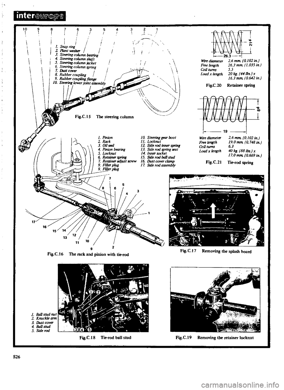
S25
Page 157 of 171
inter
Il
l
@
l
10
9
8
7
6
3
5
4
I
i
I
I
I
I
I
I
I
I
1
Snap
ring
I
2
P
antwashor
I
3
St
ng
column
bNring
4
S
eerinK
column
shaft
5
Str
nUIx
column
jacket
6
St
riJrg
column
spring
7
Dust
covu
I
8
Rubber
coupling
9
Rubber
coupling
f10nre
I
10
Str
t
rin8lcwer
joint
mbly
I
I
1
Z
I
1
J
Fig
ClS
1be
steering
column
lfj
II
J
1
Pinion
2
ck
3
Oil
i6d
4
Pinion
bearing
Locknut
6
RetlliMr
print
7
Ret11inn
adjwt
fC1
r
W
9
FiIJd
plug
9
FiJILr
p1u
1
a
Steering
gear
boot
11
Locknut
12
Sid
rodinmr
f1fUtl
13
Side
rod
5
Jring
seat
4
Inner
socket
15
Sid
rod
baD
stud
16
DustceJVqclomp
1
Z
Side
rod
assembly
7
5
2
Fig
Cl6
9
The
rack
and
pinion
with
tie
rod
I
1
il
1
W
y
o
Ol
l
r
I
J
I
t4
I
J
Z
i
I
i
r
t
I
1
Ball
stud
mil
2
Knuckkamr
3
DultCOver
4
lll
tud
5
Sid
rod
Fig
C
IS
Tie
rod
ban
stud
526
J
1
26
3
Windiameler
2
6mm
al02in
Fffl
I
ngth
J6
3
mm
1
035
in
CoillUms
5
5
Load
I
ngth
JOkg
44
b
jx
16
3
mm
0
642
in
FiS
C
20
Retainer
sprins
t
Wire
diameter
Free
Ie
Q
U
tums
Load
x
1ensth
Fig
C
21
Fig
C
17
Removing
the
splash
board
Fig
C
19
Removing
the
retainer
locknut
Page 158 of 171
Gean
all
parts
thoroughly
and
renew
if
damaged
If
the
column
shaft
or
jacket
is
excessively
damaged
the
steering
gear
housing
must
be
checked
A
damaged
bearing
must
be
replaced
together
with
the
column
jacket
assembly
Assembly
is
a
reversal
of
the
dismantling
procedures
The
column
shaft
journal
should
be
lubricated
with
multipurpose
grease
which
can
also
be
used
to
fill
up
the
dust
cover
Grease
the
needle
bearing
when
assembling
the
universal
joint
Use
the
tightest
snap
ring
available
when
fitting
the
needle
bearing
Snap
rings
are
supplied
in
oversizes
of
0
95
mm
05
mm
and
1
5
mm
0
0374
0
0413
and
0
0453
in
Installation
of
the
column
assembly
is
a
reversal
of
the
removal
procedures
Tighten
the
rubber
coupling
bolts
to
a
torque
reading
of
I
S
to
1
8
kgm
I
0
8
to
13
0
Ib
ft
Refit
the
steering
wheel
and
tighten
the
nut
to
a
reading
of
4
0
to
5
0
kgm
28
9
to
36
2Ib
ft
RACK
AND
PINION
AND
TIE
ROD
Removing
and
Dismantling
1
Jack
up
the
vehicle
and
support
it
on
stands
Remove
the
road
wheels
2
Slacken
the
bolts
connecting
the
pinion
to
the
steering
lower
joint
See
Figs
C
16
3
Remove
the
bolts
from
the
steering
column
rubber
coupl
ing
See
Fig
C
15
and
remove
the
splash
board
Fig
C
17
4
Remove
the
tie
rod
ball
stud
nut
and
disconnect
the
tie
rod
from
the
knuckle
arm
Fig
C
I8
5
Lift
the
engine
slightly
with
suitable
tackle
but
take
care
not
to
damage
the
accelerator
or
remote
control
linkage
Remove
the
bolts
securing
the
steering
gear
housing
to
the
suspension
member
Withdraw
the
rack
and
pinion
assem
bly
Dismantle
as
follows
Detach
the
steering
lower
joint
from
the
rack
and
pinion
assembly
Clamp
the
unit
in
a
vice
taking
care
not
to
damage
the
steering
gear
housing
Refer
to
Fig
C
16
and
take
off
the
dust
cover
and
boot
clamps
at
both
sides
Slacken
the
stopper
nut
remove
the
tie
rod
inner
socket
and
disconnect
the
tie
rods
from
the
rack
Withdraw
the
spring
seat
and
tie
rod
spring
Take
off
the
steering
gear
boots
at
both
sides
Slacken
the
locknut
and
disconnect
the
tie
rod
outer
socket
from
the
ball
Slacken
the
locknut
remove
the
retainer
adjusting
screw
and
withdraw
the
steering
gear
retainer
See
Fig
C
19
Take
off
the
oil
seal
remove
the
snap
ring
and
withdraw
the
pinion
Remove
the
snap
ring
and
withdraw
the
bearing
from
the
pinion
Remove
the
filler
plug
and
take
out
the
rack
Remove
the
grease
reservoir
Clcan
all
parts
thoroughly
and
replace
any
which
show
signs
of
wear
or
damage
Check
the
axial
play
of
the
inner
and
outer
ball
joints
The
play
should
be
0
06
mm
0
0024
in
for
the
inner
ball
joint
and
from
0
1
to
0
5
mm
0
0039
to
0
0197
in
for
the
outer
joints
Use
a
spring
balance
to
check
the
force
required
to
swing
the
ball
joints
this
should
be
between
0
8
to
LS
kgm
5
8
to
10
8Ib
ft
Renew
the
oil
seal
Examine
the
retainer
and
tie
rod
springs
and
compare
them
with
the
values
given
in
Figs
C
20
and
c
n
RACK
AND
PINION
AND
TIE
ROD
Assembling
and
Adjusting
Press
the
bearing
on
to
the
pinion
gear
and
fi
t
the
tigh
test
snap
ring
available
Snap
rings
are
supplied
in
the
following
over
sizes
Snap
Ring
Thicknesses
1
04
to
1
09
mm
0
0409
to
0
0429
in
1
09
to
I
14
mm
0
0429
to
0
0449
in
1
14toI19mm
0
0449toO
0469in
Ll9
to
1
24
mm
0
0469
to
0
0488
in
1
24
to
1
29
mm
0
0488
to
0
0502
in
Clamp
the
steering
gear
housing
in
a
vice
Grease
the
teeth
and
friction
surfaces
of
the
rack
with
multipurpose
grease
Lubricate
the
gear
housing
from
the
pinion
housing
side
Ensure
that
the
rack
projects
by
an
equal
amount
of
96
mm
3
8
in
in
both
ends
of
the
housing
with
the
rack
teeth
directed
towards
the
pinion
shaft
Grease
the
pinion
teeth
end
bushing
and
pinion
bearing
Engage
the
tccth
of
the
pinion
with
the
rack
and
insert
the
pinion
Make
sure
that
the
bushing
does
not
become
damaged
The
rack
must
project
from
the
housing
by
an
equal
amount
at
each
side
with
the
groove
on
the
pinion
serration
facing
upwards
Fit
the
snap
ring
into
the
housing
groove
to
hold
the
bearing
outer
race
in
position
The
snap
ring
must
fit
tightly
and
can
be
selected
from
the
following
oversizes
Snap
Ring
Thicknesses
LS5
to
1
60
mm
0
0610
to
0
0630
in
1
60
to
1
65
mm
0
0630
to
0
0650
in
1
65
to
I
70
mm
0
0650
to
0
0669
in
1
70
to
I
75
mm
0
0669
to
0
0689
in
Fit
the
oil
seal
Use
a
dial
gauge
as
shown
in
Fig
C
22
to
check
the
thrust
play
of
the
pinion
The
play
should
be
less
than
0
09mm
0
0035
in
Grease
the
retainer
and
insert
it
with
the
spring
Tighten
the
retainer
adjusting
screw
fully
then
back
it
off
by
20
to
25
degrees
Tighten
the
locknut
to
a
torque
reading
of
4
0
to
6
0
kgm
28
9
to
43
4lb
ft
Coat
the
locknut
with
liquid
pack
ing
Three
Bond
When
the
rack
and
pinion
is
assembled
measure
the
force
required
to
rotate
the
pinion
and
also
the
preload
of
the
rack
Use
a
spring
balance
as
shown
in
Figs
C
23
and
C
24
and
check
that
the
pinion
torque
is
8
to
20
kg
cm
7
to
17
Ib
in
and
the
rack
preload
is
from
8
to
18
kg
17
6
to
39
7Ibs
Take
care
to
slide
the
assembly
over
the
complete
range
of
the
stroke
Fit
a
dust
cover
clamp
at
each
end
of
the
housing
Install
the
stop
nut
on
the
threads
of
the
rack
Liberally
grease
the
ball
joint
friction
area
of
the
tie
rod
assembly
Assemble
the
spring
and
ball
seat
and
fit
the
inner
socket
part
of
the
tie
rod
assembly
to
the
rack
Make
sure
the
boot
is
positioned
at
the
ball
stud
end
Note
that
the
left
hand
tie
rod
is
marked
with
an
L
the
right
hand
rod
is
not
marked
527
Page 159 of 171
inter
C
7
j
l
l
IJ
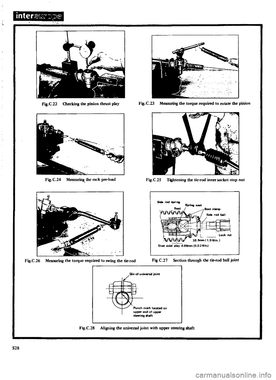
Fig
C
22
Checking
the
pinion
tluust
play
Fig
C23
ML
Io
b
the
torque
required
to
rotate
the
pinion
Fig
C
24
Measuring
the
rack
pre
load
Fig
C
25
Tightening
the
tie
rod
inner
socket
stop
nut
S
rod
I
p
ing
Boot
Spring
I
Boot
cl
np
Side
rod
1
t
I
I
Lock
n
rt
38
5n
m
1
5115in
Staaj
xial
p1
Y
o
l5errm
0
02
5in
Fig
C
26
Measuring
the
torque
required
to
swing
the
tie
rod
Fig
C
2
Section
through
the
tie
rod
ball
joint
Slila
niversatjoint
Punch
marif
located
on
upper
nd
of
upper
steering
shaft
Fig
C
28
Aligning
the
universal
joint
with
upper
steering
shaft
528
Page 163 of 171

inter
j
IJ
ITJJ
4
532
6
7
Fig
D
4
Layout
of
brake
piping
with
single
master
cylinder
3
15
7
6
e
2
1
rQt
coper
2
Adiwtint
Urim
3
dUe
4
Adiuster
5
Retum
springs
6
Anti
ttk
qJrinp
V
7
Adiwt
t
Fig
D
6
Rear
drom
brake
components
8
JIJmd
bnzke
Iner
9
Wh
1
cylinder
10
Lilli
11
A
nti
rattle
pim
3
4
1
PIIz
ed
st
tl1
2
Push
rod
3
Dittp
urtun
4
Rmr
Vrdl
J
Jbwer
phton
6
VQcwunl
OJlt
7
01
8
VQcuum
wzhe
9
fuppet
aucmb1y
10
Vah
body
pzrd
JEiID
12
II
Air
li
mur
Fzlter
12
V4lveopt
l
t1tintrod
13
Vobe
rdunuJNin8
14
lbppet
mum
Pri
If
15
AiTvah
e
16
RDut
17
Valve
plunger
18
Reaction
dUe
19
lJttp
rrqm
mum
Pri
If
20
Front
s
relJ
IS
Fig
D
Section
through
the
Master
Vac
unit
J
Bralee
rube
A
2
Front
COfIMctor
3
Bralee
tube
B
4
PreS
lJ
hO
e
front
R
H
5
Brake
tube
C
6
tubeD
7
Pressure
hose
front
L
H
8
2
way
connector
9
Brake
tube
E
10
Rear
connector
11
Pressure
hose
rear
R
12
Brake
tube
F
13
Brake
tube
G
14
PntruFe
h
e
raIT
L
H
IJ
Brake
hlbe
H
16
Hose
lock
plate
17
Hose
Jock
spring
Fig
US
Removing
the
air
silencer
retainer
Fig
D
9
Removing
the
valve
plunger
stop
key
G
lj
t
I
e
6
I
r
6
Fig
D
1O
Removing
the
bandbrake
front
cable
Page 165 of 171

Clamp
the
flange
and
bolt
assembly
in
a
vice
Push
the
rear
shell
and
stud
assembly
down
and
turn
it
anti
clockwise
to
release
Take
care
not
to
drop
the
valve
body
and
di
phrd
gm
plate
which
will
be
detached
at
the
same
time
Remove
the
retainer
and
detach
the
bearing
and
seal
from
the
rear
shelL
A
needle
can
be
used
to
remove
the
retainer
Pull
the
diaphragm
from
the
groove
in
the
diaphragm
plate
Remove
the
valve
body
guard
and
the
air
silencer
See
Fig
0
8
Remove
the
valve
plunger
stop
key
Fig
D
9
detach
the
valve
rod
and
plunger
assembly
and
the
air
silencer
fllter
from
the
valve
body
and
diaphragm
plate
Pull
out
the
reaction
di
c
To
dismantle
the
front
shell
and
stud
assembly
first
pull
out
the
push
rod
then
remove
the
plate
and
seal
and
the
check
valve
MASfER
V
AC
SERVO
UNIT
Assembling
inspect
the
components
and
replace
any
which
show
signs
of
wear
or
damage
As
previously
stated
the
repair
kit
contains
a
number
of
items
which
must
be
used
to
replace
the
original
parts
Assembly
is
a
reversal
of
the
dismantling
procedure
but
the
following
components
should
be
lubricated
with
silicon
grease
Grease
the
lip
and
face
of
the
seal
the
lip
of
the
poppet
both
faces
of
the
reaction
disc
Grease
the
diaphragm
edge
in
contact
with
the
front
and
rear
shell
Grease
the
face
of
the
plate
and
seal
assembly
which
con
tacts
the
front
shell
and
push
rod
the
face
of
the
check
valve
in
contact
with
the
packing
and
also
the
push
rod
at
the
point
of
contact
with
the
diaphragm
plate
Check
the
clearance
between
the
master
cylinder
and
push
rod
after
assembling
The
clearance
should
be
4
0
0
5
0
mm
ot
575
0
0197
0
in
and
can
be
adjusted
if
necessary
by
altering
the
length
of
the
push
rod
Installation
of
the
Master
Vac
unit
is
a
reversal
of
the
removal
procedure
HANDBRAKE
CABLES
Removing
The
cables
of
the
mechanical
handbrake
See
Fig
D
3
can
be
removed
in
the
following
manner
Front
cable
1
Release
the
hand
brake
and
disconnect
the
front
cable
by
removing
the
clevis
pin
1
in
Fig
D
I
0
at
the
handbrake
equalizer
Screw
out
the
adjusting
nut
2
to
disconnect
the
cable
from
the
handbrake
lever
2
Straighten
the
cable
clamp
I
in
Fig
D
II
and
pullout
the
the
lock
plate
2
to
extract
the
cable
from
the
retainer
3
Detach
the
cable
outer
casing
from
the
handbrake
control
bracket
then
pull
out
the
front
cable
Control
Stem
Removal
of
the
control
stem
is
a
straight
forward
opera
tion
Refer
to
Fig
D
12
and
take
out
the
clevis
pin
I
connect
ing
the
yoke
2
to
the
lever
3
Remove
the
clevis
pin
4
secur
ing
the
guide
5
to
the
bracket
6
then
withdraw
the
control
stem
S34
Re
lf
rnble
Remove
the
nut
from
the
adjuster
and
disconnect
the
left
hand
rear
cable
Disconnect
the
rear
cables
from
the
wheel
cylinders
Refer
to
Fig
D
13
pull
out
the
lock
plates
1
and
2
andremove
the
clevis
pin
HANDBRAKE
CABLES
Inspection
and
Installation
lnspect
the
cables
and
replace
them
if
any
of
the
wires
have
broken
Cables
which
have
stretched
must
be
renewed
as
it
will
no
longer
be
possible
to
adjust
the
handbrake
correctly
Check
the
springs
and
renew
them
if
they
have
weakened
or
broken
Oteck
the
centre
lever
trunnion
pin
and
equalizer
and
replace
as
necessary
Installation
is
a
reversal
of
the
removal
procedure
Grease
all
sliding
parts
and
adjust
the
handbrake
as
described
below
HANDBRAKE
Adjusting
Release
the
handbrake
and
adjust
the
rear
brake
shoes
as
described
under
the
appropriate
heading
Adjust
the
front
and
rear
cables
to
give
a
handbrake
lever
stroke
of
85
to
95
mm
0
35
to
3
74
in
by
setting
the
adjust
ing
nuts
shown
arrowed
in
Fig
D
14
BRAKE
PEDAL
Adjusting
Adjust
the
length
of
the
master
cylinder
push
rod
until
the
brake
pedal
pad
is
set
to
a
height
of
187
0
mm
7
36
in
with
the
brake
light
switch
free
from
the
pedal
stopper
Lock
the
push
rod
by
tightening
the
locknut
l
in
Fig
D
15
Screw
in
the
brake
light
switch
until
the
screwed
shaft
of
the
switch
makes
contact
with
the
stopper
brJ
cket
bolt
then
retighten
the
locknut
Adjust
the
stopper
bolt
2
until
the
brake
pedal
pad
is
set
to
a
height
of
183
0
mm
7
2
in
then
retighten
the
locknut
The
full
stroke
of
the
brake
pedal
should
now
be
set
to
150
0
mm
5
9
in
The
brake
lamps
should
light
up
when
the
pedal
is
depressed
15
0
mm
0
6
in
see
Fig
D
16
Lubricate
all
sliding
parts
with
bearing
grease
REAR
DRUM
BRAKE
Adjusting
Jack
up
the
vehicle
at
the
rear
and
release
the
handbrake
Depress
the
brake
pedal
several
times
and
turn
the
adjuster
clockwise
until
the
drum
is
locked
See
Fig
D
I
Turn
the
adjuster
in
the
opposite
direction
until
the
shoes
arc
just
dear
of
the
drum
and
the
wheel
can
be
turned
freely
by
hand
Repeat
the
operation
on
the
other
adjuster
and
then
depress
the
brake
pedal
to
make
sure
the
brakes
are
working
correctly
BLEEDING
THE
HYDRAULIC
SYSTEM
Refer
to
the
section
BRAKING
SYSTEM
for
L14
Ll6
and
LIS
engines
and
follow
the
instructions
given
under
the
appropriate
heading