brake fluid DATSUN 610 1969 Workshop Manual
[x] Cancel search | Manufacturer: DATSUN, Model Year: 1969, Model line: 610, Model: DATSUN 610 1969Pages: 171, PDF Size: 10.63 MB
Page 48 of 171
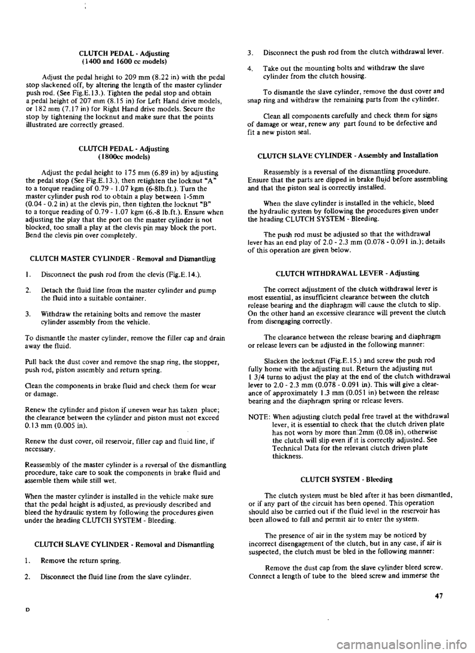
CLUTCH
PEDAL
Adjusting
400
and
1600
cc
models
Adjust
the
pedal
height
to
209
mm
8
22
in
with
the
pedal
stop
slackened
off
by
altering
the
length
of
the
master
cylinder
push
rod
See
Fig
E
13
Tighten
the
pedal
stop
and
obtain
a
pedal
height
of
207
ffim
8
15
in
for
Left
Hand
drive
models
or
182
mID
7
I7
in
for
Right
Hand
drive
models
Secure
the
stop
by
tightening
the
locknut
and
make
sure
that
the
points
illustrated
are
correctly
greased
CLlTfCH
PEDAL
Adjusting
1800cc
models
Adjust
the
pedal
height
to
175
mm
6
89
in
by
adjusting
the
pedal
stop
See
Fig
E
13
then
retighten
the
locknut
A
to
a
torque
reading
of
0
79
1
07
kgm
6
8Ib
ft
Turn
the
master
cylinder
push
rod
to
obtain
a
play
between
1
Smm
0
04
0
2
in
at
the
clevis
pin
then
tighten
the
locknut
B
to
a
torque
reading
of
0
79
1
07
kgm
6
8
Ib
ft
Ensure
when
adjusting
the
play
that
the
port
on
the
master
cylinder
is
not
blocked
too
small
a
play
at
the
clevis
pin
may
block
the
port
Bend
the
clevis
pin
over
completely
CLlTfCH
MASTER
CYLINDER
Removal
and
Dismantling
Disconnect
the
push
rod
from
the
clevis
Fig
E
14
Detach
the
fluid
line
from
the
master
cylinder
and
pump
the
fluid
into
a
suitable
container
3
Withdraw
the
retaining
bolts
and
remove
the
master
cylinder
assembly
from
the
vehicle
To
dismantle
the
master
cylinder
remove
the
filler
cap
and
drain
away
the
fluid
Pull
back
the
dust
cover
and
remove
the
snap
ring
the
stopper
push
rod
piston
assembly
and
return
spring
Oean
the
components
in
brake
fluid
and
check
them
for
wear
or
damage
Renew
the
cylinder
and
piston
if
uneven
wear
has
taken
place
the
clearance
between
the
cylinder
and
piston
must
not
exceed
0
13
mm
0
005
in
Renew
the
dust
cover
oil
reservoir
filler
cap
and
fluid
line
if
necessary
Reassembly
of
the
master
cylinder
is
a
reversal
of
the
dismantling
procedure
take
care
to
soak
the
components
in
brake
fluid
and
assemble
them
while
still
wet
When
the
master
cylinder
is
installed
in
the
vehicle
make
sure
that
the
pedal
height
is
adjusted
as
previously
described
and
bleed
the
hydraulic
system
by
following
the
procedures
given
under
the
heading
CLlTfCH
SYSTEM
Bleeding
CLlTfCH
SLAVE
CYLINDER
Removal
and
Dismantling
Remove
the
return
spring
2
Disconnect
the
fluid
line
from
the
slave
cylinder
D
3
Disconnect
the
push
rod
from
the
clutch
withdrawal
lever
4
Take
out
the
mounting
bolts
and
withdraw
the
slave
cylinder
from
the
clutch
housing
To
dismantle
the
slave
cylinder
remove
the
dust
cover
and
snap
ring
and
withdraw
the
remaining
parts
from
the
cylinder
Oean
all
components
carefully
and
check
them
for
signs
of
damage
or
wear
renew
any
part
found
to
be
defective
and
fit
a
new
piston
seal
CLUTCH
SLAVE
CYLINDER
Assembly
and
Installation
Reassembly
is
a
reversal
of
the
dismantling
procedure
Ensure
that
the
parts
are
dipped
in
brake
flu
d
before
assembling
and
that
the
piston
seal
is
correctly
installed
When
the
slave
cylinder
is
installed
in
the
vehicle
bleed
the
hydraulic
system
by
following
the
procedures
given
under
the
heading
CLlTfCH
SYSTEM
Bleeding
The
push
rod
must
be
adjusted
so
that
the
withdrawal
lever
has
an
end
play
of
2
0
2
3
mm
0
078
0
091
in
details
of
this
operation
are
given
below
CLlTfCH
WITHDRAWAL
LEVER
Adjusting
The
correct
adjustment
of
the
clutch
withdrawal
lever
is
most
essential
as
insufficient
clearance
between
the
clutch
release
bearing
and
the
diaphragm
will
cause
the
clutch
to
slip
On
the
other
hand
an
excessive
clearance
will
prevent
the
clutch
from
disengaging
correctly
The
clearance
between
the
release
bearing
and
diaphragm
or
release
levers
can
be
adjusted
in
the
following
manner
Slacken
the
locknut
Fig
E
IS
and
screw
the
push
rod
fully
home
with
the
adjusting
nut
Return
the
adjusting
nut
I
3
4
turns
to
adjust
the
play
at
the
end
of
the
clutch
withdrawal
lever
to
2
0
2
3
mm
0
078
0
091
in
This
will
give
a
clear
ance
of
approximately
1
3
mm
0
051
in
between
the
release
bearing
and
the
diaphragm
spring
or
release
levers
NOTE
When
adjusting
clutch
pedal
free
travel
at
the
withdrawal
lever
it
is
essential
to
check
that
the
clutch
driven
plate
has
not
worn
by
more
than
2mm
0
08
in
otherwise
the
clutch
will
slip
even
if
it
is
correctly
adjusted
See
Technical
Data
for
the
relevant
clutch
driven
plate
thickness
CLUTCH
SYSTEM
Bleeding
The
clutch
system
must
be
bled
after
it
has
been
dismantled
or
if
any
part
of
the
circuit
has
been
opened
This
operation
should
also
be
carried
out
if
the
fluid
level
in
the
reservoir
has
been
allowed
to
fall
and
pennit
air
to
enter
the
system
The
presence
of
air
in
the
system
may
be
noticed
by
incorrect
disengagement
of
the
clutch
but
in
any
case
if
air
is
suspected
the
clutch
must
be
bled
in
the
following
manner
Remove
the
dust
cap
from
the
slave
cylinder
bleed
screw
Connect
a
length
of
tube
to
the
bleed
screw
and
immerse
the
47
Page 51 of 171
other
end
of
the
tube
into
a
clean
container
partly
filled
with
brake
fluid
Top
up
the
master
cylinder
reservoir
with
recommended
fluid
and
open
the
bleed
screw
approximately
three
quarters
of
a
turn
Depress
the
clutch
pedal
slowly
and
hold
it
completely
down
re
tighten
the
bleed
screw
and
allow
the
pedal
to
return
slowly
Repeat
the
operation
until
the
fluid
emerging
from
the
tube
is
free
from
air
bubbles
It
should
be
noted
that
assistance
will
be
required
when
carrying
out
bleeding
operations
as
not
only
must
the
fluid
entering
the
glass
container
be
watched
but
also
the
clutch
pedal
has
to
be
operated
and
the
reservoir
topped
up
frequently
throughout
the
procedure
When
the
fluid
is
completely
free
from
air
bubbles
the
bleed
screw
should
be
retightened
on
a
down
stroke
of
the
pedal
Finally
remove
the
bleed
tube
and
replace
the
dust
cap
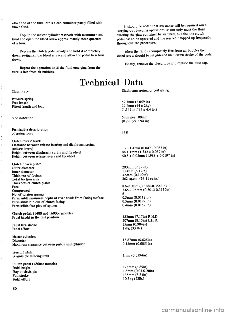
TechnIcal
Data
Outch
type
Pressure
spring
Free
length
Fitted
length
and
load
Side
distortion
Permissible
deterioration
of
spring
force
Outch
release
levers
Oearance
between
release
bearing
and
diaphragm
spring
release
levers
Height
between
diaphragm
spring
and
flywheel
Height
between
release
levers
and
flywheel
Outch
driven
plate
Outer
diameter
Inner
diameter
Thickness
of
facingS
Total
friction
area
TIrickness
of
clutch
plate
Free
Compressed
No
of
torsion
springs
Permissible
minimum
depth
of
rivet
heads
from
facing
surface
Permissible
run
out
of
clutch
facing
P
rmissible
free
play
of
splines
Outch
pedal
1400
and
1600cc
models
Pedal
height
in
the
rest
position
P
da1
free
stroke
P
da1
effort
Master
cylinder
Diameter
Maximum
clearance
between
piston
and
cylinder
Pressure
plate
Permissible
refacing
limit
Outch
pedal
180Occ
models
P
da1
height
Play
at
clevis
pin
Full
stroke
P
da1
effort
50
Diaphragm
spring
or
coil
spring
52
3mm
2
059
in
29
2mm
44
2kg
1
149
in
197
t
4
4
lb
5mm
per
IOOmm
0
2in
per
3
94
in
15
1
2
I
4mm
0
047
0
055
in
44
t
Imm
1
732
t
0
039
in
50
5
t
0
05mm
1
988
t
0
0197
in
200mm
7
87
in
130mm
5
12in
3
5mm
0
140in
362
sq
cm
56
11
sq
in
8
6
9
0mm
0
3386
o
3543in
7
65
7
95mm
0
3012
o
3130in
6
O
3mm
0
0118
in
0
5mm
0
0197
in
0
4mm
0
0157
in
182mm
7
17in
R
H
D
207mm
8
15in
L
H
D
25mm
0
984in
15kg
33
lb
15
87mm
0
625in
O
13mm
0
005lin
Imm
0
0394in
175mm
6
89in
1
5mm
0
04
0
20in
135mm
5
3lin
10
5kg
23Ib
Page 80 of 171
factory
parts
Installation
is
a
reversal
of
the
removal
procedure
REAR
SUSPENSION
ARM
Removal
and
Installation
Saloon
I
J
ad
up
the
car
at
the
rear
and
support
it
on
stands
2
Remove
the
road
wheel
and
brake
drum
as
described
in
the
section
BRAKES
3
Disconnect
the
drive
shaft
from
the
axle
shaft
4
Disconnect
the
handbrake
cable
from
the
equalizer
bracket
and
the
wheel
cylinder
lever
Disconnect
the
brake
hose
from
the
brake
line
by
removing
the
lock
spring
and
then
withdrawing
through
the
connector
Plug
the
end
of
the
brake
line
to
avoid
loss
of
fluid
and
ingress
of
dirt
5
Remove
the
wheel
bearing
locknut
Fig
H
9
the
rear
axle
shaft
wheel
bearings
and
oil
seal
Remove
the
rear
brake
assembly
from
the
suspension
ann
See
section
BRAKES
6
Jack
up
the
suspension
arm
to
relieve
the
tension
on
the
shock
absorber
and
disconnect
the
shock
absorber
from
the
lower
mounting
Lower
the
jack
gradually
and
remove
the
coil
spring
seat
and
bump
rubber
7
Remove
the
bolts
securing
the
suspension
arm
to
the
suspension
member
Fig
H
IO
and
withdraw
the
suspension
arm
The
rubber
bushes
can
be
drawn
out
of
the
suspension
arm
if
necessary
using
the
special
tool
ST
38280000
Fig
H
Il
O1eck
the
suspension
arm
for
distortion
or
cracks
and
inspect
the
rubber
bushes
for
signs
of
wear
or
damage
Renew
any
part
which
is
unsatisfactory
Installation
is
a
reversal
of
the
removal
procedure
Tighten
all
the
suspension
arm
mounting
bolts
with
the
weight
of
the
vehicle
resting
on
the
rear
wheels
The
self
locking
nuts
must
be
renewed
at
each
overhaul
REAR
AXLE
SHAFTS
BEARINGS
AND
SEALS
Saloon
Removal
and
Dismantling
I
Raise
the
vehicle
at
the
rear
and
place
stands
under
the
body
member
2
Remove
the
road
wheel
and
brake
drum
3
Disconnect
the
drive
shaft
from
the
axle
shaft
and
remove
the
wheel
bearing
locknut
The
special
wrench
ST
38060001
can
be
used
to
hold
the
flange
as
shownin
Fig
H
12
4
Withdraw
the
axle
shaft
assembly
as
shown
in
Fig
H
13
using
the
special
tool
ST
07640000
and
sliding
hammer
ST
36230000
Remove
the
rear
axle
drive
flange
5
Use
a
suitable
drift
or
special
tool
ST
37750000
See
Fig
H
14
to
drive
out
the
inner
bearing
and
oil
seal
F
6
Remove
the
grease
retainer
and
withdraw
the
outer
bearing
with
a
conventional
puller
DO
NOT
re
use
this
outer
bearing
REAR
AXLE
SHAFTS
BEARINGS
AND
SEALS
Saloon
Assembly
and
Installation
Oleck
the
axle
shaft
for
straightness
make
sure
that
it
is
not
cracked
or
damaged
in
any
way
00
NOT
heat
the
shaft
if
attempting
to
re
straighten
Make
sure
that
the
lip
of
the
oil
seal
is
not
damaged
or
distorted
Check
the
bearing
for
excessive
wear
and
damage
Oean
the
wheel
bearings
the
oil
seal
and
the
inside
of
the
axle
housing
When
installing
the
wheel
bearings
the
sealed
side
of
the
outer
bearing
should
face
the
wheel
and
the
sealed
side
of
the
inner
bearing
should
face
the
differential
See
Fig
H
IS
Pressure
must
be
applied
to
the
inner
race
when
fitting
When
replacing
the
suspension
arm
check
that
the
distance
piece
is
0
05
mm
0
002
in
shorter
than
the
length
of
the
housing
dimension
LI
See
Fig
H
16
The
distance
piece
and
axle
housing
code
markings
must
coincide
The
wheel
bearing
grease
must
be
replaced
every
50
000
km
30
000
miles
Pack
the
wheel
bearings
with
grease
at
the
positions
shown
in
Fig
H
IS
and
coat
the
lip
of
the
oil
seal
Renew
the
locknut
and
oil
seal
at
each
overhaul
Wheel
bearing
adjustment
Tighten
the
locknut
to
the
specified
torque
reading
of
25
33
kgm
181
239
lb
ft
and
check
that
the
rear
axle
shaft
end
play
does
not
exceed
0
15
mm
0
006
in
with
a
turning
torque
of
less
than
7
kg
em
6
11b
in
for
the
1400
and
1600cc
models
510
series
or
4
5
kg
em
3
91b
in
for
the
1800cc
610
series
If
the
correct
end
play
or
turning
torque
cannot
be
obtained
it
will
be
necessary
to
change
the
distance
piece
See
above
DRIVE
SHAFTS
Removal
and
Dismantlill8
Disconnect
the
end
flanges
and
remove
the
shaft
See
Fig
H
17
The
drive
shaft
should
only
be
dismantled
to
lubricate
the
splines
This
operation
will
only
be
necessary
every
two
years
or
50
000
km
30
000
miles
Remove
the
universal
joint
spider
at
the
differential
side
Refer
to
the
propeller
shaft
section
Remove
the
snap
ring
securiilg
the
sleeve
yoke
plug
and
take
out
the
plug
Compress
the
drive
shaft
and
remove
the
snap
ring
and
stopper
Fig
H
17
Disconnect
the
boot
and
split
the
shaft
Make
sure
that
the
balls
and
spacers
are
retained
DRIVE
SHAFTS
Inspection
and
Assembly
The
drive
shaft
should
be
replaced
as
an
assembly
if
any
part
is
found
to
be
defective
Check
the
shaft
for
straightness
damage
or
wear
Old
79
Page 84 of 171
Front
SuspensIon
DESCRIPTION
WHEEL
HUBS
WHEEL
BEARINGS
Adjusting
FRONT
AXLE
AND
SUSPENSION
ASSEMBLY
DESCRIPTION
The
front
suspension
is
of
the
strut
type
with
the
coil
spring
and
hydraulic
damper
units
mounted
on
the
suspension
member
and
transverse
link
assembly
See
FigJ
1
Vertical
movement
of
the
suspension
is
controlled
by
the
strut
assembly
the
tension
rod
absorbs
the
forward
and
backward
movement
of
the
transverse
links
whilst
side
move
ment
of
the
body
is
controlled
by
the
stabilizer
rod
which
is
attached
to
the
body
and
transverse
links
WHEEL
HUBS
Removal
1
Jack
up
the
vehicle
remove
the
road
wheel
and
disconnect
the
brake
hose
at
the
strut
outer
casing
bracket
as
described
under
the
previous
heading
Plug
the
opened
end
of
the
hose
to
prevent
loss
of
fluid
2
Remove
the
brake
calliper
assembly
or
the
brake
drum
as
described
in
the
section
BRAKES
3
Remove
the
grease
cap
from
the
hub
by
tapping
lightly
at
the
joint
using
a
screwdriver
and
hammer
4
Withdraw
the
cotter
pin
from
the
wheel
bearing
locknut
and
remove
the
nut
Remove
the
wheel
hub
together
with
the
wheel
bearing
and
washer
Fig
J
2
On
cars
fitted
with
disc
brakes
the
hub
is
removed
complete
with
brake
disc
5
The
wheel
bearing
outer
race
can
be
removed
from
the
hub
using
a
drift
as
shown
in
Fig
I
3
WHEEL
HUBS
Inspection
and
Overhaul
Gean
the
hub
and
bearings
by
washing
in
petrol
Examine
the
grease
seal
and
make
sure
that
it
is
not
worn
or
cracked
renew
the
seal
if
necessary
Ensure
that
the
races
are
not
pitted
or
scored
rotate
them
and
check
for
signs
of
wear
and
play
A
sectional
view
of
the
wheel
bearing
assembly
is
given
in
Fig
14
to
provide
an
indication
of
the
points
to
be
checked
WHEEL
HUB
AND
BEARING
Installation
The
wheel
bearing
outer
race
can
be
refitted
with
a
suitable
drift
or
special
tool
ST
35310000
Fill
the
wheel
hub
and
the
hub
cap
to
the
positions
shown
in
Fig
J
5
with
multi
purpose
grease
Fill
the
spaces
between
the
bearing
rollers
and
the
lip
of
the
grease
seal
with
the
same
type
of
grease
Lightly
smear
the
spindle
shaft
and
threads
the
bearing
washer
and
bearing
lock
SPRING
AND
STRUT
ASSEMBLY
TRANSVERSE
LINK
AND
LOWER
BALL
JOINT
FRONT
WHEEL
ALIGNMENT
ADJUSTING
THE
STEERING
ANGLE
nut
with
grease
and
assemble
the
parts
onto
the
wheel
spindle
Make
sure
that
dirt
and
foreign
matter
does
not
adhere
to
the
greased
surfaces
Adjust
the
wheel
bearings
as
described
under
the
following
heading
WHEEL
BEARINGS
Adjusting
The
wheel
bearings
can
be
adjusted
with
the
road
wheel
the
hub
cap
and
the
bearing
locknut
cotterpin
removed
as
previously
described
Tighten
the
wheel
bearing
locknut
to
a
torque
reading
of
3
0
3
5
kgm
21
7
25
3lb
ft
Turn
the
hub
several
times
in
each
direction
to
settle
the
bearing
and
then
retighten
the
bearing
locknut
to
the
specified
torque
reading
Slacken
the
bearing
locknut
to
an
angle
between
40
to
700
a
ay
from
the
previously
tightened
position
and
align
the
cotter
pin
hole
with
the
hole
in
the
spindle
Turn
the
wheel
hub
a
few
times
in
each
direction
and
then
measure
the
torque
required
to
cause
the
hub
to
turlI
A
spring
balance
should
be
used
as
shown
m
Rig
J
p
make
sure
that
the
brake
pads
are
not
binding
on
the
disc
type
of
brake
unit
and
check
that
the
force
required
to
turn
the
hub
is
within
the
following
fIgures
Wheel
bearing
rotation
starting
torque
1800ce
With
new
bearing
7
0
kg
cm
97
in
oz
1400
1600cc
With
new
bearing
8
0
kg
cm
111
2
in
oz
With
used
bearing
4
0
kg
cm
56
0
in
oz
Starting
torque
at
the
hub
bolt
lWth
new
bearing
ith
used
bearings
1
57
kg
3
46
lb
0
7
kg
1
541b
Adjust
the
locknut
slightly
if
the
fIgures
do
not
conform
and
replace
the
cotterpin
Refit
the
hub
cap
and
the
road
wheel
FRONT
AXLE
AND
SUSPENSION
ASSEMBLY
Removal
Jack
up
the
front
of
the
vehicle
and
place
stands
under
the
ront
side
members
Remove
the
road
wheels
and
the
splash
board
3
Disconnect
the
front
brake
hoses
and
remove
the
brake
hose
locking
springs
Withdraw
the
plates
and
remove
the
hoses
from
the
strut
assembly
Plug
the
ends
of
the
hoses
to
prevent
the
ingress
of
dirt
and
loss
of
fluid
4
Remove
the
cotter
pin
from
the
tie
rod
ball
joint
remove
83
Page 88 of 171
the
castle
nut
and
detach
the
tie
rod
from
the
knuckle
arm
5
Remove
the
tension
rod
securing
nuts
Fig
J
7
remove
the
bolts
and
withdraw
the
tension
rod
Withdraw
the
nut
shown
arrowed
in
FigJ
8
and
remove
the
stabilizer
6
Support
the
engine
with
suitable
lifting
tackle
so
that
the
engine
mounting
bolts
can
be
removed
and
the
suspension
crossmember
detached
from
the
engine
FigJ
9
7
Place
ajack
under
the
crossmember
Remove
the
bolts
indicated
in
Fig
J
IO
and
separate
the
crossmember
from
the
body
8
Remove
the
strut
assembly
upper
attachment
self
locking
nuts
at
both
sides
Fig
J
ll
and
lower
the
front
suspension
assembly
to
remove
it
from
the
vehicle
FRONT
AXLE
AND
SUSPENSION
ASSEMBLY
Installation
Installation
is
a
reversal
of
the
removal
procedure
noting
the
following
points
Make
sure
that
all
rubber
parts
are
free
from
wear
and
deterioration
Any
part
of
the
suspension
assembly
which
has
been
damaged
or
distorted
must
be
replaced
The
front
wheel
alignment
should
be
checked
after
completing
the
installation
a
brief
description
is
given
at
the
end
of
this
section
Camber
and
castor
angles
are
preset
and
cannot
be
adjusted
SPRING
AND
STRUf
ASSEMBLY
Removal
and
Installation
The
strut
assembly
consists
of
the
outer
casing
piston
rod
piston
rod
guide
and
cylinder
etc
An
exploded
view
of
the
components
is
given
in
Fig
J
12
The
inner
components
must
be
replaced
as
a
complete
assembly
Replacement
and
overhaul
procedures
for
the
inner
components
together
with
the
removal
of
the
front
springs
should
only
be
carried
out
by
a
specialist
Datsun
workshop
The
strut
assembly
can
be
removed
prior
to
dismantling
by
following
the
procedures
outlined
below
Jack
up
the
front
of
the
vehicle
and
support
it
on
stands
2
Disconnect
the
brake
hose
from
the
strut
assembly
bracket
as
previously
described
under
the
heading
FRONT
AXLE
and
SUSPENSION
ASSEMBLY
Removal
3
Remove
the
stabilizer
bar
and
tension
rod
from
the
trans
verse
links
Loosen
and
remove
the
knuckle
arm
fixing
bolts
Fig
J
9
And
separate
the
strut
assembly
from
the
ball
joints
4
Remove
the
strut
assembly
upper
attachment
self
locking
nuts
Fig
J
11
and
withdraw
the
strut
assembly
from
the
body
Fig
J
13
Installation
is
a
reversal
of
the
removal
procedure
Ensure
that
the
bolts
are
tightened
to
the
specified
torque
readings
given
under
TIGHTENING
TORQUES
SPRING
AND
STRUT
ASSEMBLY
Dismantling
and
Assembly
Care
must
be
taken
when
dismantling
the
assembly
to
ensure
that
aU
parts
are
maintained
in
a
clean
condition
Clamp
the
suspension
strut
assembly
in
a
vice
and
fit
the
special
attachment
ST
2770000
I
to
the
lower
end
of
the
strut
Prise
off
the
dust
cover
snap
ring
Use
the
coil
spring
compressor
ST
35650001
to
slightly
compress
the
spring
Remove
the
self
locking
nut
and
take
off
the
mounting
insulator
thrust
bearing
spring
seat
and
bump
rubber
Slacken
the
spring
compressor
and
remove
the
spring
Push
down
the
shock
absorber
piston
until
it
bottoms
and
remove
the
gland
packing
with
the
special
tool
ST
35500001
Fig
J
14
Remove
the
O
ring
from
the
piston
rod
guide
and
lift
out
the
piston
rod
and
cy
linder
assembly
00
NOT
separate
the
piston
and
cylinder
which
are
serviced
as
a
complete
assembly
Drain
all
fluid
from
the
suspension
unit
and
shock
absorber
assembly
Wash
all
parts
thoroughly
not
rubber
parts
in
petrol
or
a
suitable
solvent
The
gland
packing
and
0
ring
must
be
renewed
at
each
overhaul
Always
refill
with
the
correct
grade
of
fresh
oil
in
accordance
with
the
information
in
the
table
below
ATSUGI
KAYABA
Part
No
54302
UO
100
UOl10
325
cc
332
cc
54302
3
U0500
1
54302
N
1200
325
cc
300
cc
The
oil
quantity
is
extremely
critical
as
it
will
affect
the
damping
power
of
the
shock
absorber
To
assemble
fit
the
rubber
O
ring
on
the
top
of
the
piston
rod
and
refit
the
gland
packing
Take
care
that
the
oil
seal
does
not
become
damaged
during
the
latter
operation
Lift
the
piston
rod
up
by
approximately
90
mm
3
5
in
before
tightening
the
gland
packing
to
facilitate
bleeding
then
tighten
the
packing
to
a
torque
reading
of
7
13
kgm
51
94Jb
ft
Bleed
the
shock
absorber
by
pumping
the
piston
rod
up
and
down
until
the
pressure
is
the
same
in
both
directions
Position
the
coil
spring
bump
rubber
spring
seat
and
dust
cover
on
the
top
of
the
piston
rod
The
piston
rod
must
be
in
the
fully
extended
position
Compress
the
spring
fit
the
strut
mounting
insulator
and
bearing
assembly
Tighten
the
self
locking
nut
to
a
torque
reading
of
6
7
5
kgm
43
541b
ft
SPRING
AND
STRUT
ASSEMBLY
Installation
Installation
is
a
reversal
of
the
removal
procedure
Thoroughly
grease
the
parts
marked
in
Fig
J
15
Tighten
the
fixing
bolts
to
the
torque
readings
given
in
TIGHfENING
TORQUES
TRANSVERSE
LINK
AND
LOWER
BALL
JOINT
Removal
The
transverse
link
with
rubber
bushing
is
connected
to
the
suspension
crosSlTIember
by
a
mounting
bolt
as
shown
in
Fig
J
11
and
to
the
strut
assembly
via
the
lower
ball
joint
87
Page 100 of 171
BrakIng
System
DESCRIPTION
MASTER
CYLINDER
Removal
dismantling
and
Overhaul
BRAKE
LINES
Replacing
BRAKE
WARNING
LIGHT
SWITCH
FRONT
DRUM
BRAKE
Removal
inspection
and
Overhaul
REAR
DRUM
BRAKE
Removal
inspection
and
Overhaul
FRONT
DRUM
BRAKE
Adjusting
DESCRIPTION
The
vehicle
is
fitted
with
either
disc
brakes
or
two
leading
shoe
type
drum
brakes
for
the
front
wheels
and
leading
trailing
shoe
type
drum
brakes
for
the
rear
wheels
All
brakes
are
hydraulically
operated
from
the
brake
pedal
with
the
rear
brakes
additionally
operated
by
a
mechanical
handbrake
and
linkage
system
Either
a
single
or
a
tandem
master
cylinder
can
be
fitted
The
tandem
master
cylinder
provides
a
dual
braking
circuit
in
which
the
front
and
rear
brakes
are
separately
supplied
If
ODe
circuit
fails
the
other
circuit
will
still
operate
and
provide
a
reduced
but
efficient
braking
action
The
brake
pipes
are
double
wall
steel
tubes
and
are
galvanized
at
the
sections
beneath
the
vehicle
floor
to
prevent
corrosion
MASTER
CYLINDER
Removal
Either
a
tandem
or
single
master
cylinder
can
be
fitted
to
the
vehicle
Fig
L
I
shows
a
cross
sectional
view
through
the
tandem
master
cylinder
and
Fig
L
2
a
cross
sectional
view
through
the
single
master
cylinder
The
removal
and
dismantling
procedures
are
similar
for
both
types
and
are
carried
out
in
the
following
manner
1
Remove
the
clevis
pin
and
separate
the
brake
pedal
from
the
master
cylinder
push
rod
2
Disconnect
the
brake
tubes
from
the
master
cylinder
3
Remove
the
master
cylinder
mounting
bolts
withdraw
the
shims
and
take
out
the
master
cylinder
assembly
MASfER
CYLINDER
Dismantling
and
Overhaul
Drain
the
brake
fluid
from
the
cylinder
and
remove
the
stopper
bolt
Remove
the
dust
cover
the
snap
ring
the
stopper
ring
and
the
pusbrod
assembly
Take
out
the
primary
piston
and
secondary
piston
assemblies
and
the
piston
spring
Remove
the
valve
cap
and
take
out
the
valve
assembly
Oean
all
the
components
with
brake
fluid
and
check
them
for
wear
or
damage
Make
sure
that
the
cylinder
bore
and
piston
are
not
damaged
or
unevenly
worn
The
clearance
between
cylinder
and
piston
must
not
exceed
0
15mm
0
006
in
REAR
DRUM
BRAKE
Adjusting
FRONT
DISC
BRAKE
Friction
pads
FRONT
DISC
BRAKE
Removal
and
Dismantling
FRONT
DISC
BRAKE
Assembly
and
Installation
HANDBRAKE
Removal
and
Installation
BLEEDING
THE
HYDRAULIC
SYSTEM
BRAKE
PEDAL
ADJUSTMENT
Check
the
return
springs
for
damage
or
loss
of
tension
Replace
any
part
which
is
in
an
unsatisfactory
condition
MASfER
CYLINDER
Assembly
and
Installation
Assembly
of
the
master
cylinder
is
a
reversal
of
the
dismantling
procedure
noting
the
following
points
Wet
the
cylinder
bore
and
piston
etc
with
brake
fluid
before
assembling
Care
must
be
taken
to
prevent
dust
and
foreign
matter
entering
the
cylinder
and
reservoir
Ensure
that
cups
and
soals
are
not
damaged
when
locating
them
After
the
master
cylinder
is
reinstalled
the
system
must
be
bled
and
the
pedal
height
adjusted
as
described
under
the
appropriate
headings
BRAKE
LINES
Replacing
The
layout
of
the
metal
brake
pipes
and
flexible
hoses
is
shown
in
Fig
L
3
The
brake
pipes
can
be
removed
by
taking
off
the
flare
nuts
at
both
ends
of
the
pipe
and
removing
the
clips
securing
the
pipe
to
the
body
Similarly
the
brake
hoses
can
be
removed
by
taking
off
the
flare
nuts
Thoroughly
clean
the
pipe
or
hose
after
removing
from
the
vehicle
and
check
for
collapsing
cracking
or
rusting
of
the
pipe
and
for
signs
of
expansion
and
weakening
of
the
hose
Any
pipe
or
hose
which
is
not
in
a
satisfactory
condition
must
be
renewed
Remove
any
dust
from
the
brake
clip
and
replace
the
clip
if
the
vinyl
coating
is
torn
Installation
is
a
reversal
of
the
removal
procedure
Make
sure
that
the
brake
pipes
cannot
vibrate
against
any
part
of
the
vehicle
and
the
brake
hoses
are
not
twisted
and
rubbing
against
the
tyres
or
suspension
units
If
the
brake
hose
is
disconnected
from
the
three
way
connector
on
the
rear
axle
housing
it
will
be
necessary
to
fit
a
new
copper
sealing
washer
Do
not
overtighten
the
installation
flare
nuts
the
correct
tightening
torques
are
as
follows
Three
way
connector
master
cylinder
and
brake
hoses
1
5
1
8
kgm
II
13Ib
ft
Fill
the
master
cylinder
with
recommended
fluid
and
bleed
the
system
as
described
under
the
appropriate
heading
Make
sure
that
fluid
is
not
leaking
from
any
part
of
the
system
by
fully
depressing
the
brake
pedal
for
several
seconds
Check
the
pipes
and
connections
and
replace
any
defective
part
99
Page 102 of 171
BRAKE
WARNING
UGHT
SWITCH
A
hydraulically
operated
warning
light
switch
is
located
in
the
engine
compartment
Fig
LA
The
front
and
rear
brake
systems
of
the
dual
circuit
are
connected
to
the
switch
which
provides
a
warning
via
the
warning
light
on
the
instrument
panel
when
a
pressure
difference
of
13
17
kg
sq
cm
185
242Ib
sq
in
occurs
between
the
front
and
rear
brake
systems
The
switch
cannot
be
repaired
and
must
be
renewed
if
faulty
FRONT
DRUM
BRAKE
Removal
1
Jack
up
the
front
of
the
vehicle
and
support
it
on
stands
2
Remove
the
brake
drum
and
the
hub
cap
and
hub
assembly
3
Disconnect
the
brake
pipe
at
the
bracket
on
the
front
suspension
strut
as
previously
described
in
the
section
FRONT
SUSPENSION
4
Unhook
the
two
return
springs
shown
in
Fig
L
5
and
remove
the
brake
shoes
5
Disconnect
the
bridge
pipe
3
in
Fig
L
6
and
remove
the
two
wheel
cylinders
6
Take
out
the
installation
bolts
and
withdraw
the
brake
backplate
from
the
spindle
FRONT
DRUM
BRAKE
Inspection
and
Overhaul
Examine
the
brake
drums
for
scoring
and
out
of
round
The
maximum
permissible
inner
diameter
of
the
drums
must
not
exceed
228
6mm
9
00
in
and
out
of
round
should
be
below
0
02mm
0
0008in
The
brake
shoe
linings
must
re
renewed
when
worn
down
to
a
thickness
of
1
5mm
0
06
in
or
below
Renew
the
linings
if
they
are
contaminated
in
any
way
or
incorrectly
seated
The
complete
set
of
linings
must
be
replaced
if
any
single
lining
is
unsatisfactory
O1eck
the
shoe
return
springs
and
if
they
have
become
weakened
replace
them
Withdraw
the
pistons
and
springs
from
the
wheel
cylinders
and
inspect
the
bore
of
the
cylinders
for
signs
of
wear
corrosion
or
damage
Renew
the
cylinder
and
the
piston
if
the
clearance
between
the
two
exceeds
O
15mm
0
006
in
Renew
the
rubber
boots
and
cups
FRONT
DRUM
BRAKE
Assembly
and
Installation
Assembly
and
installation
is
a
reversal
of
the
removal
and
dismantling
procedure
noting
the
fOllowing
points
Apply
a
thin
layer
of
special
grease
to
the
piston
cup
and
other
rubber
parts
when
assembling
the
wheel
cylinder
The
internal
components
of
the
cylinder
should
be
dipped
in
brake
fluid
and
assembled
whilst
still
wet
Install
the
wheel
cylinders
on
the
brake
backplate
and
smear
the
cylinder
backplate
and
cylinder
lever
fulcrum
with
grease
Fig
L
8
Tighten
the
backplate
mounting
bolts
to
a
torque
reading
of
2
7
3
7
kgm
19
5
26
71b
ft
Adjust
the
brake
shoes
and
bleed
the
hydraulic
system
as
described
under
the
appropriate
headings
REAR
DRUM
BRAKE
REMOVAL
Fig
L
IO
Jack
up
the
vehicle
at
the
rear
and
support
it
on
stands
Remove
the
road
wheel
2
Release
the
handbrake
remove
the
clevis
pin
3
from
the
rear
wheel
cylinder
lever
4
see
Fig
L
9
Disconnect
the
handbrake
cable
2
and
remove
the
return
spring
I
3
Remove
the
brake
drum
Remove
the
shoe
retainers
the
return
springs
and
brake
shoes
Fig
L
II
4
Disconnect
the
fluid
line
from
the
wheel
cylinders
and
plug
the
opened
end
to
prevent
to
loss
of
fluid
5
Remove
the
dust
cover
adjusting
shims
and
plates
then
remove
the
wheel
cylinder
from
the
backplate
6
The
brake
backplate
and
axle
shaft
assembly
can
be
with
drawn
if
necessary
by
taking
out
the
four
flange
bolts
and
removing
the
assembly
as
described
in
the
section
REAR
AXLE
AND
REAR
SUSPENSION
REAR
DRUM
BRAKE
Inspection
and
Overhaul
The
inspection
and
overhaul
procedures
fpr
the
rear
drum
brakes
are
similar
to
those
previously
described
for
the
front
drum
brakes
Tighten
the
brake
backplate
mounting
bolts
to
a
torque
reading
of
3
9
5
3
kgm
28
38Ib
ft
FRONT
DRUM
BRAKE
Adjusting
Jack
up
the
vehicle
and
pump
the
brake
pedal
several
times
With
the
brake
drum
installed
turn
one
of
the
adjusting
cams
clockwise
until
the
brake
shoe
is
in
contact
with
the
drum
This
operation
is
carried
out
from
the
rear
of
the
backplate
When
the
brake
shoe
contacts
the
drum
turn
the
cam
in
the
opposite
direction
until
the
shoe
is
just
clear
and
the
brake
drum
can
be
rotated
freely
by
hand
Repeat
the
operation
on
the
other
adjusting
cam
and
then
depress
the
brake
pedal
to
make
sure
that
the
brakes
are
working
correctly
The
adjusters
must
be
released
slightly
if
the
brake
drum
binds
when
turned
by
hand
Fig
L
12
shows
the
adjusting
cams
REAR
DRUM
BRAKE
Adjusting
Jack
up
the
vehicle
at
the
rear
and
pump
the
brake
pedal
several
times
Turn
the
brake
shoe
adjuster
Fig
L
13
until
the
101
Page 104 of 171
brake
shoe
is
in
contact
with
the
drum
The
adjuster
must
be
turned
from
the
rear
of
the
backplate
and
the
drum
turned
by
hand
When
the
shoe
contacts
the
drum
turn
the
adjuster
in
the
opposite
direction
until
the
shoe
is
just
clear
and
the
drum
can
be
rotated
freely
by
hand
Depress
the
brake
pedal
and
make
sure
that
the
brakes
operate
correctly
The
adjusters
must
be
released
slightly
if
the
brake
shoe
binds
FRONT
DISC
BRAKE
Friction
pads
Fig
L
14
The
disc
brakes
are
self
adjusting
but
the
friction
pads
should
be
checked
for
wear
every
5
000
km
3
000
miles
and
replaced
if
the
thickness
of
the
friction
lining
on
any
pad
is
less
than
1
0mm
0
004
in
In
effect
this
means
that
renewal
is
necessary
when
the
total
thickness
of
pad
and
lining
is
less
than
8
4mm
0
24
in
To
replace
the
friction
pads
proceed
as
follows
Siphon
out
some
of
the
fluid
in
the
master
cylinder
reservoir
Jack
up
the
front
of
the
vehicle
and
remove
the
road
wheel
Remove
the
anti
rattle
clip
from
the
calliper
plate
Fig
L
lS
Unhook
the
hanger
spring
and
withdraw
the
brake
pads
and
shims
Fig
L
17
It
should
be
noted
that
the
friction
pads
must
be
replaced
as
a
set
and
renewed
at
both
sides
of
the
vehicle
otherwise
the
braking
action
will
be
uneven
Oean
the
calliper
and
pad
at
their
installation
positions
Press
the
pistons
into
the
calliper
bores
so
that
the
new
friction
Pads
can
be
installed
The
pistons
can
be
installed
by
applying
light
pressure
as
shown
in
Fig
L
16
but
care
must
be
taken
to
avoid
pushing
them
too
far
or
the
groove
of
the
piston
will
damage
the
seal
If
the
pistons
are
pushed
down
excessively
it
will
be
necessary
to
dismantle
the
calliper
as
described
under
the
appropriate
heading
Assemble
the
anti
squeal
shims
to
the
friction
pads
with
the
arrow
mark
on
the
shims
pointing
in
the
direction
of
forward
disc
rotation
Refit
the
pads
and
retaining
pins
and
assemble
the
coil
spring
to
the
retaining
pin
furthest
away
from
the
air
bleed
screw
After
installing
the
new
pads
and
shims
depress
the
brake
pedal
several
times
to
reposition
the
pistons
in
the
calliper
O1eck
the
fluid
level
in
the
master
cylinder
reservoir
and
refill
to
the
correct
level
FRONT
DISC
BRAKE
Removal
and
Dismantling
1
Jack
up
the
front
of
the
vehicle
remove
the
road
wheel
and
take
out
the
friction
pads
2
Disconnect
the
brake
hose
from
the
brake
tube
and
plug
the
opened
end
to
prevent
the
loss
of
fluid
3
Remove
the
bolts
securing
the
brake
calliper
to
the
knuckle
flange
and
remove
the
calliper
assembly
Fig
L
IS
4
Remove
the
hub
nut
and
withdraw
the
hub
and
disc
To
dismantle
the
calliper
remove
the
anti
rattle
clip
and
withdraw
the
brake
pads
Remove
the
tension
springs
and
pull
the
cylinder
out
of
the
calliper
Blow
out
the
piston
with
com
pressed
air
applied
at
the
brake
hose
connection
Oean
the
components
in
brake
fluid
and
examine
them
for
signs
of
wear
or
damage
The
cylinder
walls
can
be
carefully
polished
with
fine
emery
cloth
if
they
are
rusted
or
contaminated
If
the
parts
are
excessively
corroded
they
should
be
renewed
Replace
the
pistons
if
they
are
unevenly
worn
damaged
or
rusted
The
sliding
surface
of
the
piston
is
plated
and
no
attempt
should
be
made
to
use
emery
cloth
or
similar
abrasives
for
cleaning
purposes
Check
the
thickness
of
the
friction
pads
as
previously
described
and
replace
them
if
necessary
Renew
the
piston
seals
and
the
dust
covers
O1eck
the
brake
disc
for
scoring
and
out
of
round
The
standard
disc
thickness
is
10
Omm
0
0394
in
and
must
not
be
reground
below
8
4mm
0
3307
in
Check
the
disc
run
out
with
a
dial
gauge
as
shown
in
Fig
L
19
Position
the
gauge
near
the
outer
diameter
and
check
that
the
run
out
does
not
exceed
0
06mm
0
0024
in
FRONT
BRAKE
DISC
Assembly
and
Installation
Rinse
the
cylinder
bore
with
brake
fluid
and
fit
the
piston
seal
into
the
cylinder
groove
Fig
L
20
Fit
the
wiper
seal
and
lightly
grease
the
bore
of
the
cylinder
Clean
the
brake
disc
and
fit
it
to
the
hub
Install
the
hub
to
the
knuckle
spindle
Carefully
insert
the
piston
into
the
cylinder
until
the
face
of
the
piston
is
almost
flush
with
the
wiper
seal
retainer
The
relieved
part
of
the
piston
should
face
the
piston
pin
Fit
the
cylinder
to
the
calliper
plate
and
secure
in
position
with
the
two
torsion
springs
Assemble
the
hold
down
pin
the
spring
washer
and
the
nut
to
the
support
bracket
Secure
the
nut
with
a
cotter
pin
Assemble
the
calliper
to
the
mounting
bracket
using
the
pivot
pin
washer
spring
washer
and
nut
Tighten
the
nut
and
secure
with
a
cotter
pin
Hook
the
hold
down
bracket
to
the
top
of
the
mounting
bracket
and
turn
the
calliper
plate
to
make
sure
that
it
can
slide
smoothly
Fit
the
calliper
assembly
to
the
knuckle
flange
Fit
a
shim
to
the
inner
pad
and
insert
the
pad
Draw
the
calliper
towards
the
chassis
and
insert
the
lower
cuts
on
the
pad
into
the
mounting
bracket
and
push
the
pad
in
until
it
contacts
the
piston
Move
the
calliper
away
from
the
chassis
and
insert
the
upper
cuts
Centre
the
indentation
of
the
outer
pad
in
the
calliper
plate
Fit
the
anti
rattle
clip
Fig
L
14
103
Page 106 of 171
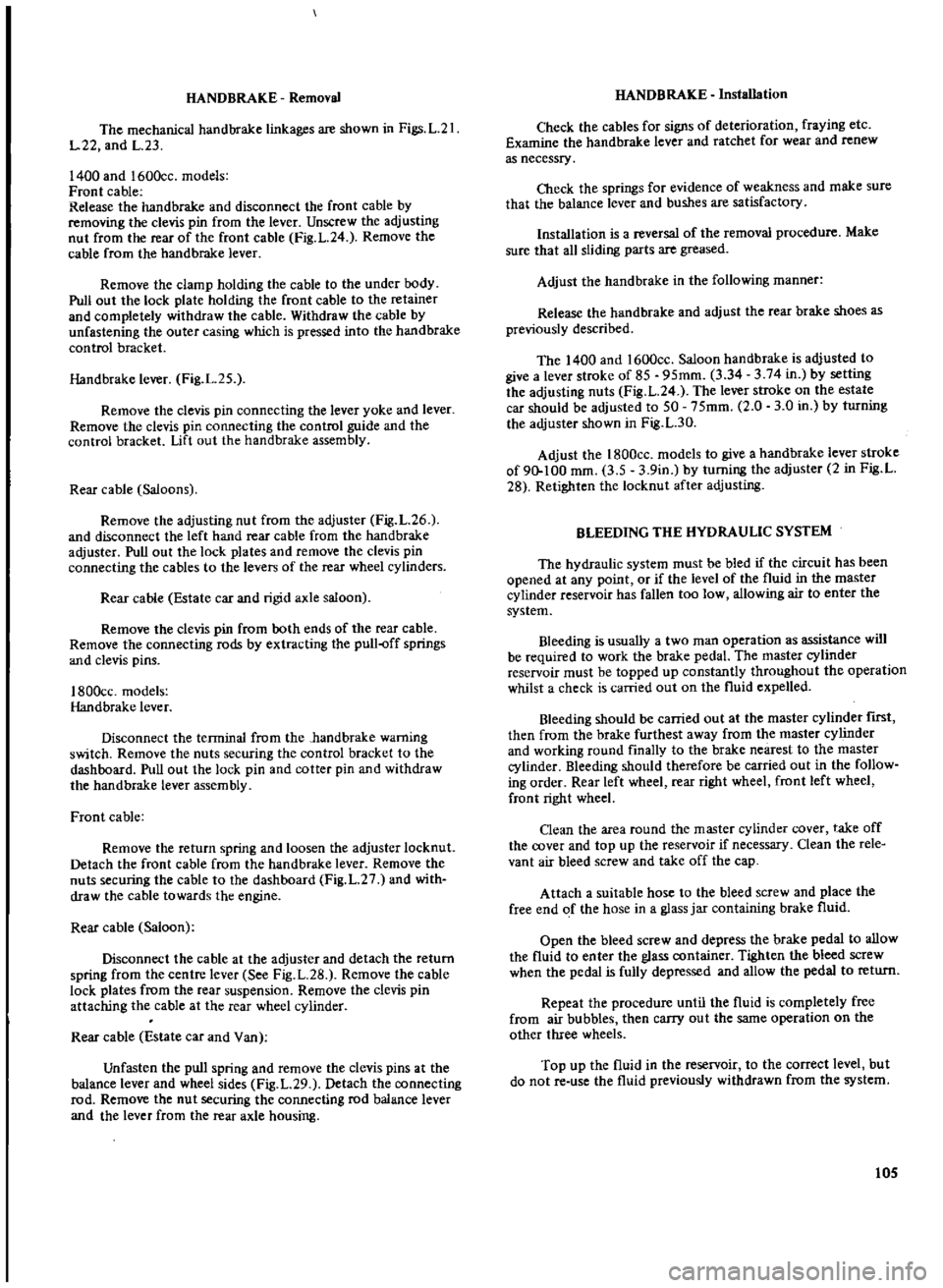
HAND
BRAKE
Removal
The
mechanical
handbrake
linkages
are
shown
in
Figs
L
21
1
22
and
1
23
1400
and
1600cc
models
Front
cable
Release
the
hand
brake
and
disconnect
the
front
cable
by
removing
the
clevis
pin
from
the
lever
Unscrew
the
adjusting
nut
from
the
rear
of
the
front
cable
Fig
L
24
Remove
the
cable
from
the
hand
brake
lever
Remove
the
clamp
holding
the
cable
to
the
under
body
Pull
out
the
lock
plate
holding
the
front
cable
to
the
retainer
and
completely
withdraw
the
cable
Withdraw
the
cable
by
unfastening
the
outer
casing
which
is
pressed
into
the
handbrake
control
bracket
Handbrake
lever
Fig
1
25
Remove
the
clevis
pin
connecting
the
lever
yoke
and
lever
Remove
the
clevis
pin
connecting
the
control
guide
and
the
control
bracket
Lift
out
the
handbrake
assembly
Rear
cable
Saloons
Remove
the
adjusting
nut
from
the
adjuster
Fig
L
26
and
disconnect
the
left
hand
rear
cable
from
the
handbrake
adjuster
Pull
out
the
lock
plates
and
remove
the
clevis
pin
connecting
the
cables
to
the
levers
of
the
rear
wheel
cylinders
Rear
cable
Estate
car
and
rigid
axle
saloon
Remove
the
clevis
pin
from
both
ends
of
the
rear
cable
Remove
the
connecting
rods
by
extracting
the
puU
off
springs
and
clevis
pins
1800cc
models
Handbrake
lever
Disconnect
the
terminal
from
the
hand
brake
warning
switch
Remove
the
nuts
securing
the
control
bracket
to
the
dashboard
Pull
out
the
lock
pin
and
cotter
pin
and
withdraw
the
handbrake
lever
assembly
Front
cable
Remove
the
return
spring
and
loosen
the
adjuster
10cknuL
Detach
the
front
cable
from
the
handbrake
lever
Remove
the
nuts
securing
the
cable
to
the
dashboard
Fig
L
27
and
with
draw
the
cable
towards
the
engine
Rear
cable
Saloon
Disconnect
the
cable
at
the
adjuster
and
detach
the
return
spring
from
the
centre
lever
See
Fig
L
28
Remove
the
cable
lock
plates
from
the
rear
suspension
Remove
the
clevis
pin
attaching
the
cable
at
the
rear
wheel
cylinder
Rear
cable
Estate
car
and
Van
Unfasten
the
pull
spring
and
remove
the
clevis
pins
at
the
balance
lever
and
wheel
sides
Fig
L
29
Detach
the
connecting
rod
Remove
the
nut
securing
the
connecting
rod
balance
lever
and
the
lever
from
the
rear
axle
housing
HANDBRAKE
Installation
Check
the
cables
for
signs
of
deterioration
fraying
etc
Examine
the
handbrake
lever
and
ratchet
for
wear
and
renew
as
necessry
Check
the
springs
for
evidence
of
weakness
and
make
sure
that
the
balance
lever
and
bushes
are
satisfactory
Installation
is
a
reversal
of
the
removal
procedure
Make
sure
that
all
sliding
parts
are
greased
Adjust
the
hand
brake
in
the
following
manner
Release
the
hand
brake
and
adjust
the
rear
brake
shoes
as
previously
described
The
1400
and
1600cc
Saloon
handbrake
is
adjusted
to
give
a
lever
stroke
of
85
95mm
3
34
3
74
in
by
setting
the
adjusting
nuts
Fig
L
24
The
lever
stroke
on
the
estate
car
should
be
adjusted
to
50
75mm
2
0
3
0
in
by
turning
the
adjuster
shown
in
Fig
L
30
Adjust
the
1800cc
models
to
give
a
handbrake
lever
stroke
of
90
100
mm
3
5
3
9in
by
turning
the
adjuster
2
in
Fig
L
28
Retighten
the
locknut
after
adjusting
BLEEDING
THE
HYDRAULIC
SYSTEM
The
hydraulic
system
must
be
bled
if
the
circuit
has
been
opened
at
any
point
or
if
the
level
of
the
fluid
in
the
master
cylinder
reservoir
has
fallen
too
low
allowing
air
to
enter
the
system
Bleeding
is
usually
a
two
man
operation
as
assistance
will
be
required
to
work
the
brake
pedal
The
master
cylinder
reservoir
must
be
topped
up
constantly
throughout
the
operation
whilst
a
check
is
carried
out
on
the
fluid
expelled
Bleeding
should
be
carried
out
at
the
master
cylinder
nrst
then
from
the
brake
furthest
away
from
the
master
cylinder
and
working
round
finally
to
the
brake
nearest
to
the
master
cylinder
Bleeding
should
therefore
be
carried
out
in
the
follow
ing
order
Rear
left
wheel
rear
right
wheel
front
left
wheel
front
right
wheel
Oean
the
area
round
the
master
cylinder
cover
take
off
the
cover
and
top
up
the
reservoir
if
necessary
Clean
the
rele
vant
air
bleed
screw
and
take
off
the
cap
Attach
a
suitable
hose
to
the
bleed
screw
and
place
the
free
end
of
the
hose
in
a
glass
jar
containing
brake
fluid
Open
the
bleed
screw
and
depress
the
brake
pedal
to
allow
the
fluid
to
enter
the
glass
container
Tighten
the
bleed
screw
when
the
pedal
is
fully
depressed
and
allow
the
pedal
to
return
Repeat
the
procedure
until
the
fluid
is
completely
free
from
air
bubbles
then
carry
out
the
same
operation
on
the
other
three
wheels
Top
up
the
fluid
in
the
reservoir
to
the
correct
level
but
do
not
re
use
the
fluid
previously
withdrawn
from
the
system
105
Page 168 of 171
MO
MI
1224
D
I
KM
f
fMn
n
r
A
A
JP
I
I
T
I
I
I
Drain
ill
Changeelemenl
I
42
Cleantlement
3
I
II
r
I
Check
il
topup
4
I
Chinnloil
511
1
11
41
Gle
nelern
n
Ii
I
Orainlluid
7
I
I
I
I
Clunertmtn
81
1
I
I
I
I
I
27
Check
ailltop
up
Jf71
r
I
JIO
WI
28
Change
il
I
ill
limittdSlip
DiHlranti
1
Clleck
ilftopup
1J
I
I
I
Changelil
11
i
ill
ShdmgJolntt
Df
YlShlft
Check
11IIOpup
n
II
I
I
ChangeDl1
1
I
I
I
I
SHOCKASSORBERS
Check
Il
topup
5
PROP
DRIVESHAFTISI
lubncate
Hi
1
GREASE
GUN
POINTS
lubnCIl
it
PEOAlSHAFT
Sj
Lubrlc
te
18
HANDBHAKE
lubnc
1t
I
I
r
1
t
R
IINKAl
iF
luhncll
2u
I
I
i
I
ARlUWIORED
WHEELS
FREE
1m
I
I
i
1121
wHEE
L
tll
AHINli
ronl
HepitCk
211
t
f
WHEEl
BEARINGS
Rur
Repack
77
U
I
BRAKE
FLUID
R
nfWfbletd
1
I
lf
13
117
I
t
I
AH
UUWI
f
t1UN
11Itl
ih1tl
1
i
lcl
Check
oillevtl
B
l
r1i
BI1I1I1
r
Cap
Cleen
1ifj
j
I
Air
Cluner
Service
el
m
nt
l
J7
4
Replace
element
l
l
B
L
5
Cteenfilter
1
C
l
I
I
I
4
Clun
va
vellllR
I
I1
I
I
I
Repl
cH
lve
1
I
I
I
I
Cleen
jets
bOM
R
t
I
Top
liP
pisl
dempe
l
I
r
L
LlIbncatelinkages
I
I
L
Ctean
replace
5
j
I
Ch
ckoill
ve1
Ei
l
j
16
Clun
replac
n
11
R
fill
witll
fluid
38
I
Check
fluid
levll
IlL
t
I
CI
ign
toil
t
i
I
t
1
l
9
CheCk
top
u
p
10
Flulhryst
m
y
Cllecksolullon
44
Chltk
45
Lubrlc
tt
46
i
Clleck
top
up
L
L
Check
topup
4
aJdM
Cllltkspet
gl1vity
i
CI
en
gr
1S
liD
116
Lubriclt
1il
If
I
II
Clleck
topup
52
1
i
Chtck
topuplluid
3
I
I
Gre
rlm
4
I
1
I
I
I
Clunfiltlr
55
L
I
I
I
Chick
top
up
fluid
I6
w
W
e
I
ofi
Ldtir
1
Renewfiltlr
58
I
Check
topupflu
d
i91
i
I
i
Renrwfluid
I
I
I
I
I
ilinlil1r
11
I
I
I
I
I
I
CAR
DOWN
E
TERNAL
j
II
1
I
1
lOCKS
HINGES
Ell
Lubrictt
S21
r
1
el
L
Door
Dram
Hol
l
Clun
f
J
I
I
WIPER
SPINDLES
lubrictt
64
W
I
I
En
in
Dil
Filwr
GttrbOK
1968
Lubricate
and
Clean
ENGINE
Filt
r
GEARBOX
Dvttdrivt
Filt
r
AUTOMATIC
TRANSM
Filt
r
DIFFERENTIAL
PCV
Syllem
rburettor
s
FUll
Bowl
Filter
S1
Fu
llnjectionPump
Fittll
ll
AUTOMATIC
TRANSM
DISTRIBUTOR
Spindl
Ctm
COOLING
SYSTEM
CorrDlionlnllibitor
Anti
Frltl
W
t
rPump
CREENWASHER
ArrERY
Connections
3ENERATOR
STEERING
POMrStlering
CLUTCH
BRAKE
BRAKE
SERVO
HYDR
SUSPENSION
CAPACITIES
LUBRICANTS
Il
D
P
LUSClu
Service
Check
Adjust
CAR
UP
I
l
lletksumpbulttortM
1
Clled
rque
i6
ServiceJndclean
J1
Adjult
brake
bandl
tB
RtnMsumpgal
tt
fiS
Check
llJmpbnlttort
PROP
lOAIVE
SHAFT
S
Check
lor
wear
JJ
Tiglltenbolu
Jl
Check
tor
wear
n
Tiglltenboltl
Clllckbootgeiltrl
Clleckoperltion
Ch
CQmpon
l
welr
Tighten
bolts
Clleclbootgaiterl
Checktorqu
Gheck
edjult
Clllck
ljust
CIIRCk
adjult
Clleck
tighltnbolts
W
M
KSI
1
t
heCklMliiili
86
Check
ldjust
81
Overllllulcompl
rvll
Cleen
chltkwtlr
R9
Check
for
wear
0
Check
9
Checkforwp
lr
192
Il1Ipecttyrel
1IJ
Illte
II
blIl1nCl
Adjultpres
lure
Cllecktorul
liON
ET
OPE
l
heckcompression
Checktorqul
AdjUltclttr
nc
CheckoptTltion
Check
lIljLllt
AdjUlI
Clleck
alIj
tension
adj
t
nsion
I
Clun
selpp
jt1
Renew
Chetk
tPoint
tp
Renew
pointl
Check
6djult
110
J
Check
edjult
ill
i
ii
j
Tiglltenhoseclips
112
R
plece
lIastl
ill
PreSSIJ
test
114
1
STEERING
Clleek
play
adjust
ill
j
i
itl
e
Ti9htenboltl
ill
ii
Geometry
Check
U1L
H
CHECK
FOR
Oil
FUEL
WATER
etc
LEAKS
1181
I
I
R
DOWN
FXIE
HNA
11
1
1
lIGHTS
If
isfHUMt
NTS
Check
flll
C
lOn
f
3
Headlights
Checkllhgnmlnt
112Cr
WIPERS
Checkbladu
11111
J
TS
r
h
kIl
CII
I
Jrl7
iI
An
UH
OVNAUOMFTER
I
ST
I
BRAKES
CheCkemCienCY
1
I
AUTOMATIC
TRANSM
Clleek
op
rttioQ
T
ENGINE
Adjust
if
required
12
DEFECTS
Report
12
EVERY
MOnthl
Miles
1000
KMs
1000
lIBt
wtJichewl
ENGINE
EngmlMountings
Engine
Film
Trap
AUTOMATIC
TRANSM
24
2
30
SUSP
FRONT
REAR
Shock
Ablorb
rs
STEERING
1
21
5
1
c
e
U
80lTS
HANDBRAKE
CLUTCH
GEAR
LINKAGE
EXHAUST
SYSTEM
f
HFf
K
FOR
Oil
FllE
1
CAH
LUWI
RI
If
WHEEL
BEARINGS
BRAKES
UningsJDruml
Plds
Discl
Selhdj
Meclleni5l11
Cylinders
Hosel
ROAD
WHEELS
3S
Whe
1
Nun
AHllIIWN
ENGINE
Cyllnd
r
Held
Vllyes
Clloke
MiKtulli
ldling
linkagel
Timing
Ch
in
16
V
Belt
Is
SPARK
PLUGS
OISTRIBUTOR
Owell
Angle
Ignition
Timing
COOLING
SYSTEM
8
X
Automatic
Diffrrrntill
ICoolinginc
Ht
lltel
AntilrH1f
Ltr
lmoP
Ugo
IL
dmo
PII
U
Ou
HydrJBrak
Fluid
4
7
1
21
81
7
ULlma
II
USP
ULlmD
USP
L
L
tmoP
USQu
127
2
4
4
SAE
3O
2OW
411
SAE
lfrN
2fJ
IOWI3O
SAE1OW
IOW
30
320C
JOe
o
e
SAE80
EP
SAE90EP
SAE
140
EP
mmDIIIII
Ifn
c
ID
WIthDv
1
LI
obWt7
3
LtrJ
PtLUSPtL
3
2
0
75
T
3
1
8
B
8
WAGON
1
1
72
1
TYPE
A
SUFFIX
A
SAE80
EP
SAE90EP
SAE
140EP
0
aSoC
BFl
AUTOSERVICE
DATA
CHART
DATSUI
D
FurlT
nk
n
tln
G
0
Slltring
Re
I
lm
r
JSGI
11
1
No
4S
8
9
11
9
11
17
18
19
20
41
82
84
52
SSS
95
SAElll
SAE
80
c
14O