ECO mode DATSUN 610 1969 Workshop Manual
[x] Cancel search | Manufacturer: DATSUN, Model Year: 1969, Model line: 610, Model: DATSUN 610 1969Pages: 171, PDF Size: 10.63 MB
Page 4 of 171
inteN
j
@IP
B
Index
ENGINE
COOLING
SYSTE
l
IGNITION
SYSTE
I
FUEL
SYSTBl
CLUTCH
GEARUOX
PROPELLER
SHAFT
Id
DIFFERENTIAL
REAR
AXLE
nd
REAR
SUSPENSION
FRONT
SUSPENSION
STEERING
BRAKING
SYSTEM
ELECTRICAL
EQUIP
JENT
WIRING
JAGRA
IS
TROUBLE
SHOOTING
TIGHTENING
TORQUES
SERIES
C
30
MODEL
SUPPLEMENT
AUTOSERVlCE
DATA
CHART
PART
NA
ES
nd
ALTERNATIVES
CONVERSION
TABLES
S
15
2S
33
43
51
62
7S
83
91
9S
lOB
liB
I2S
129
51
End
of
manuir
IntroductIon
OUf
intention
in
writing
this
Manual
is
to
provide
the
reader
with
all
the
data
and
in
formation
required
to
maintain
and
repair
the
vehicle
However
it
must
be
realised
that
special
equipment
and
skills
arc
required
in
some
caseS
to
carry
out
the
work
detailed
in
the
text
and
we
do
not
recommend
that
such
work
be
attempted
unless
the
reader
possesses
the
necessary
skill
and
equipment
It
would
be
better
to
have
an
AUTHQRISED
DEALER
to
carry
out
the
work
using
the
special
tools
and
equipment
available
to
his
trained
staff
He
will
also
be
in
possession
of
the
genuine
spare
parts
which
may
be
needed
for
replacement
The
information
in
the
Manual
has
been
checked
against
that
provided
by
the
vehicle
manufacturer
and
any
peculiarities
have
been
mentioned
if
they
depart
rom
usual
work
shop
practice
A
fault
finding
and
trouble
shooting
chart
has
been
inserted
at
the
end
of
the
Manual
to
enable
the
reader
to
pin
point
faults
and
so
save
time
As
it
is
impossible
to
include
every
malfunction
only
the
more
usual
ones
have
been
included
A
composite
conversion
table
has
also
been
included
at
the
end
of
the
manual
and
we
would
recommend
that
wherever
possible
for
greater
accuracy
the
metric
system
units
are
used
Brevity
and
simplicity
have
been
our
aim
in
compiling
this
Manual
relying
on
the
number
ous
illustrations
and
clear
text
to
inform
and
instruct
the
reader
At
the
request
of
the
many
users
of
our
Manuals
we
have
slanted
the
book
towards
repair
and
overhaul
rather
than
maintenance
Although
every
care
has
been
taken
to
ensure
that
the
information
and
data
are
correct
WE
CANNOT
ACCEPT
ANY
LIABILITY
FOR
INACCURACIES
OR
OMISSIONS
OR
FOR
DAMAGE
OR
MALFUNCTIONS
ARISING
FROM
THE
USE
OF
THIS
BOOK
NO
MATTER
HOW
CAUSED
I
3
Page 22 of 171
Wear
limit
Crank
pin
journal
diameter
Max
crankpin
taper
Max
crankpin
out
of
round
Thickness
of
main
bearing
shells
0
3
mm
0
012
in
49
961
49
975
mm
1
967
1
9675
in
0
03
mm
0
012
in
0
03
mm
0
012
in
1
827
1
835
mm
0
072
0
0722
in
Main
bearing
running
clearance
0
020
0
062
mm
0
0008
0
0024
in
Max
main
bearing
running
clearance
Crankshaft
bend
limit
Material
Type
Piston
diameters
Standard
I
st
oversize
2nd
oversize
3rd
oversize
4th
oversize
5th
oversize
Width
of
ring
grooves
Top
and
second
Oil
control
Piston
running
clearance
0
12
mm
0
0047
in
0
05
mm
0
002
in
PISTONS
Cast
aluminium
Slipper
skirt
82
99
83
04
mm
3
267
3
269
in
83
22
83
27
mm
3
276
3
278
in
83
47
83
52
mm
3
286
3
288
in
83
72
83
77
mm
3
296
3
298
in
83
97
84
02
mm
3
305
3
308
in
84
47
84
52
mm
3
326
3
328
in
2
0
mm
0
08
in
4
0
mm
0
16
in
0
025
0
045
mm
0
001
0
002
in
PISTON
PIN
Pin
diameter
20
995
21
000
mm
0
8266
0
8268
in
Pin
length
72
00
72
25
mm
2
8346
2
8445
in
Pin
running
clearance
in
piston
0
008
0
010
mm
0
0003
0
0004
in
Pin
interference
fit
in
small
end
bush
0
015
0
033
mm
0
0006
0
0013
in
Piston
ring
height
Top
and
second
Oil
control
Side
clearance
in
grooves
Top
PISTON
RINGS
2
0
mm
0
08
in
4
0
mm
0
16
in
0
040
0
073
mm
0
0016
0
0029
in
Second
Oil
control
Piston
ring
gaps
Top
Second
Oil
control
Material
Distortion
of
sealing
face
Max
distortion
Valve
seat
insert
material
Inlet
Exhaust
Fit
Drive
Chain
Chain
tensioner
0
030
0
063
mm
0
0012
0
0025
in
0
025
0
063
mm
0
001
0
0025
in
0
23
0
38
mm
0
0091
0
0150
in
0
15
0
30
mm
0
006
0
012
in
0
15
0
30
mm
0
006
0
012
in
CYLINDER
HEAD
Aluminium
alloy
0
03
mm
0
0012
in
0
1
mm
0
004
in
Aluminium
bronze
Special
cast
Hot
pressed
CAMSHAFT
DRIVE
From
crankshaft
double
roller
type
Spring
and
oil
pressure
control
Engine
model
lWIN
CHOKE
CARBURE
ITOR
Outlet
diameter
Venturi
diameter
Main
jet
Main
air
bleed
Slow
running
jet
Power
jet
Float
level
Fuel
pressure
Weight
Altitude
setting
main
jet
1000
m
3300
ft
94
2000
m
6600
ft
92
3000
m
10
000
ft
89
4000
m
13
300
ft
87
5000
m
16
600
ft
85
PRIMARY
L13
SECONDARY
30mm
27x
12mm
150
90
180
26
mm
21
x
8
mm
96
80
43
40
23
I
mm
0
905
0
04
in
0
24
kg
sq
em
3
41b
sq
in
2
55
kg
5
61
lb
1
21
Page 34 of 171
Fuel
System
DESCRIPTION
FUEL
TANK
FUEL
PUMP
CARBURETTOR
IDLING
ADJUSTMENT
FAST
IDLE
OPENING
ADJUSTMENT
THROTTLE
VALVES
INTERLOCK
OPENING
DASHPOT
DESCRIPTION
The
diaphragm
type
fuel
pump
shown
in
Fig
D
1
feeds
fuel
from
the
tank
to
the
carburettor
in
a
regulated
supply
according
to
the
needs
of
the
engine
A
cartridge
type
fuel
strainer
prevents
any
dirt
from
reaching
the
pump
inlet
valve
The
carburettor
fitted
to
the
engine
is
either
a
down
draught
two
barrel
type
equipped
with
a
throttle
operated
acceleration
pump
and
power
valve
mechanism
See
Fig
D
2
or
a
twin
SU
carburettor
of
the
type
shown
in
Fig
D
3
In
the
two
barrel
type
carburettor
fuel
flows
from
the
passage
at
the
bottom
of
the
float
chamber
passes
through
the
primary
main
jet
and
mixes
with
air
introduced
through
the
main
air
bleed
screw
The
petrol
and
air
mixture
is
injected
into
the
venturi
through
the
main
nozzle
Each
time
the
accelerator
pedal
is
depressed
the
throttle
opens
and
the
accelerator
pump
forces
a
jet
of
petrol
into
the
air
stream
to
allow
the
engine
to
accelerate
smoothly
See
Fig
0
4
The
power
valve
mechanism
is
operated
automatically
according
to
the
demands
made
by
the
engine
Under
light
load
i
e
part
throttle
conditions
the
intake
manifold
depression
is
transmitted
below
the
throttle
valve
the
vacuum
pulls
a
piston
upwards
against
a
spring
and
leaves
the
power
valve
closed
allowing
additional
air
to
be
admitted
through
the
air
bleed
screw
and
thereby
weaken
the
petrol
and
air
mixture
When
the
vacuum
below
the
throttle
vaJve
is
lowered
during
full
load
conditions
the
piston
is
pushed
down
opening
the
power
valve
and
providing
additional
fuel
to
enrichen
the
mixture
The
model
HJ
L
38W6
SU
twin
carburettor
is
of
the
horizontal
variable
venturi
type
and
is
used
only
on
the
1600
and
1800
cc
engines
In
this
type
of
carburettor
a
constant
flow
of
intake
air
is
maintained
by
the
automatically
adjusted
venturi
opening
this
is
accomplished
by
the
suction
piston
sliding
in
accordance
with
changes
in
the
volume
of
intake
air
Referring
to
Fig
D
5
the
suction
chamber
is
mounted
above
the
venturi
The
suction
piston
slides
vertically
within
the
chamber
and
changes
the
venturi
opening
area
The
piston
is
operated
by
a
difference
between
the
upper
vacuum
pressure
which
is
applied
through
the
suction
poct
and
the
atmospheric
pressure
which
is
introduced
through
the
air
hole
from
the
air
cleaner
The
amount
by
which
the
throttle
is
opened
causes
the
suction
piston
to
rise
or
fall
under
the
intluence
of
the
engine
suction
The
pozzle
opening
therefore
changes
and
provides
an
optimum
air
fuel
mixture
at
all
engine
speeds
The
cartridge
type
fuel
strainer
utilizes
a
fibre
strainer
element
which
should
be
replaced
every
20
000
km
12
000
miles
Removal
of
the
fuel
strainer
is
a
simple
operation
but
as
it
cannot
be
drained
the
strainer
should
not
be
removed
when
CARBURETIOR
Removal
and
Overhaul
FLOAT
LEVEL
Adjustment
SU
TWIN
CARBURmORS
Adjustments
SU
TWIN
CARBURmORS
Dismantling
SU
TWIN
CARBURETTORS
Inspection
STARTING
INTERLOCK
VALVE
OPENING
HYDRAULIC
DAMPER
the
tank
is
full
unless
absolutely
necessary
A
viscous
paper
type
air
cleaner
element
is
fitted
which
does
not
require
cleaning
and
should
be
repl
ced
every
40
000
km
24
000
miles
The
air
cleaner
fitted
on
the
single
carburettor
is
equipped
with
an
idling
compensator
to
prevent
the
mixture
from
becoming
too
rich
at
high
idling
temperatures
Additional
fresh
air
is
introduced
into
the
inlet
manifold
by
the
action
of
a
bimettalic
strip
located
in
the
air
cleaner
When
the
temperature
under
the
bonnet
is
high
the
bimetal
is
heated
by
the
hot
inlet
air
and
lifts
to
allow
the
valve
to
open
The
idling
compensator
valve
partially
opens
at
550
I310F
and
is
fully
open
at
650C
l490F
The
unit
cannot
be
dismantled
as
it
is
pre
sealed
and
correctly
adjusted
for
valve
timing
Fig
D
6
shows
the
layout
of
the
idling
compensator
piping
FUEL
TANK
Replacing
The
fuel
tank
can
be
removed
in
the
following
manner
Remove
the
rear
seat
and
back
rest
2
Take
out
the
board
behind
the
back
rest
3
Take
out
the
luggage
compartment
lining
board
and
disconnect
the
cable
to
the
petrol
gauge
unit
4
Disconnect
the
petrol
filler
tube
from
the
tank
5
Remove
the
tank
retaining
bolts
and
disconnect
the
rubber
fuel
outlet
and
return
hoses
Installation
is
a
reversal
of
the
removal
procedure
always
ensure
that
the
fuel
lines
arc
carefully
checked
for
signs
of
damage
before
replacing
the
tank
FUEL
PUMP
Testing
Pressure
and
capacity
tests
can
be
carried
out
with
the
pump
installed
in
the
following
manner
Static
pressure
test
Disconnect
the
fuel
line
at
the
carburettor
install
an
adaptor
tee
fitting
and
suitable
pressure
gauge
to
the
fuel
line
between
carburettor
and
fuel
pump
Start
the
engine
and
run
it
at
varying
speeds
The
reading
on
the
gauge
should
be
0
18
0
24
kg
sq
cm
2
6
34
Ib
sq
in
If
the
pressure
is
below
the
specified
figure
then
either
one
part
of
the
pump
has
worn
excessively
or
general
wear
has
occured
to
all
the
working
parts
The
faults
may
include
a
ruptured
diaphragm
worn
and
warped
valves
33
Page 43 of 171
Connect
the
fuel
line
from
the
float
chamber
to
the
nozzle
nipple
and
tighten
the
retaining
clip
Pull
out
the
choke
lever
and
place
the
connecting
plaie
betw
n
the
washer
and
sleeve
collar
Screw
the
plate
to
the
nozzle
head
and
check
that
the
collar
is
installed
in
the
hole
in
the
plate
by
mo
ing
the
choke
lever
as
necessary
Recheck
the
piston
to
make
sure
that
it
falls
freely
without
binding
SU
TWIN
CARBURETTOR
Centering
the
jet
Remove
the
damper
oil
cap
nut
and
gradually
raise
the
lifter
pin
4
in
Fig
D
17
Continue
to
raise
the
lifter
pin
until
the
head
of
the
pin
raises
the
piston
by
approximately
8
mm
0
31
in
When
the
lifter
pin
is
released
the
piston
should
drop
freely
and
strike
the
venturi
with
a
light
metallic
click
If
the
pi
ston
does
not
fall
freely
it
will
be
necessary
to
dismantle
the
carburettor
in
the
manner
previously
described
SU
TWIN
CARBURETTOR
FLOAT
LEVEL
Inspection
and
Adjustment
The
fuel
level
in
the
float
chamber
can
be
checked
using
the
special
gauge
ST
19200000
Remove
the
float
chamber
drain
plug
and
install
the
special
gauge
as
shown
in
Fig
D
20
Start
the
engine
and
allow
it
to
run
at
idling
speed
The
fuel
level
is
conect
if
it
is
indicated
on
the
glass
tu
be
at
a
distance
of
22
24
mm
0
866
0
945
in
below
the
top
of
the
float
chamber
The
level
of
the
fuel
can
be
corrected
if
necessary
by
adjusting
the
float
level
in
the
following
manner
Take
out
the
float
chamber
coveT
securing
screws
and
lift
off
the
cover
and
attached
float
lever
Hold
the
cover
so
that
the
float
lev
r
is
facing
upwards
Lift
the
float
lever
and
then
lower
it
until
the
float
lever
seat
just
contacts
the
valve
stem
The
dimension
uH
in
Fig
D
1
should
be
11
12
mm
0
43
0
47
in
and
can
be
corrected
by
bending
the
float
lever
at
the
point
indicated
SU
TWIN
CARBURETTOR
Starting
interlock
valve
opening
adjustment
To
adjust
the
starting
interlock
opening
the
connecting
rod
4
in
Fig
D
22
1
must
be
bent
using
a
suitable
pair
of
pliers
The
throttle
opening
can
be
increased
by
lengthening
the
connecting
rod
or
reduced
by
shortening
the
rod
The
throttle
opening
is
correctly
adjusted
when
the
clearance
8
between
the
throttle
valve
and
throttle
chamber
is
set
to
0
6
mm
0
023
in
with
the
choke
lever
half
completely
out
HYDRAULIC
DAMPER
The
damper
oil
should
be
checked
approximately
every
5000
km
3000
miles
To
check
the
oil
level
remove
the
oil
cap
nut
as
shown
in
Fig
D
23
and
check
the
level
of
oil
against
the
two
grooves
on
the
plunger
rod
Top
up
with
SAE
20
engine
oil
if
the
oil
level
is
below
the
lower
of
the
two
grooves
Take
care
not
to
bend
the
plunger
rod
when
removing
and
replacing
the
oil
cap
nut
and
make
sure
that
the
nut
is
sufficiently
tightened
by
hand
TechnIcal
Data
Engine
Model
Ll4
I400cc
Primary
Secondary
28mm
32mm
21x7mrn
28xlOmm
96
165
60
60
I
Omm
220
100
1
6
Outlet
diameter
Venturi
diameter
Main
jet
Main
air
bleed
1
st
slow
air
bleed
2nd
slow
air
bleed
Economizer
Power
jet
Float
level
Fuel
pressure
Main
nozzle
55
22mm
0
24
kg
sq
cm
3
41b
sq
in
2
2mm
2
Smm
SU
Twin
Carburettors
Type
Bore
diameter
Piston
lift
Jet
needle
Nozzle
jet
diameter
Suction
spring
IUL
38
W6
38mm
1
4961
in
29mm
1417
in
M
76
2
34
mm
0
0921
in
No
23
Float
needle
valve
inner
diameter
Float
level
1
5mm
0
059
in
23mm
0
9055
in
42
Ll6
1600cc
Primary
Secondary
28mm
32mm
22x7mm
29xlOmm
102
165
60
60
1
0mm
180
100
1
6
Ll8
l80Occ
Primary
Secondary
30mm
34mm
23x14x7mm
30xlOmm
102
170
60
60
I
Omm
210
100
1
6
55
22mm
55
22m
2
3mm
2
5mm
2
3mm
2
8mm
Throttle
clearance
at
full
throttle
Position
at
full
throttle
0
6mm
0
0236
in
6
50
FUEL
PUMP
Type
Delivery
amount
Mechanical
1000cc
minute
at
1000
r
p
m
0
18
0
24
kg
sq
cm
2
5
3
41b
sq
in
from
eccentric
on
cam
shaft
Delivery
pressure
Drive
Page 51 of 171
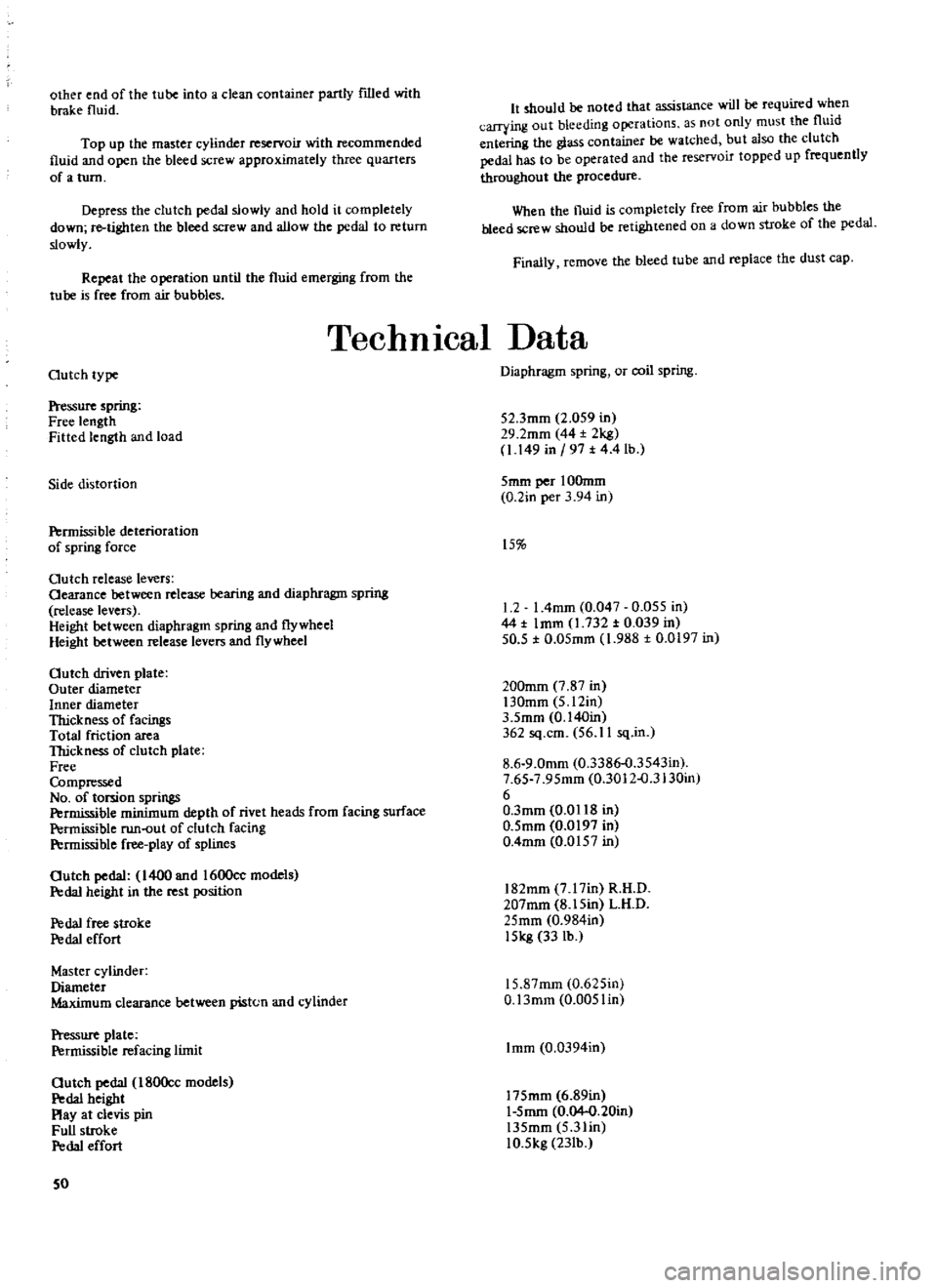
other
end
of
the
tube
into
a
clean
container
partly
filled
with
brake
fluid
Top
up
the
master
cylinder
reservoir
with
recommended
fluid
and
open
the
bleed
screw
approximately
three
quarters
of
a
turn
Depress
the
clutch
pedal
slowly
and
hold
it
completely
down
re
tighten
the
bleed
screw
and
allow
the
pedal
to
return
slowly
Repeat
the
operation
until
the
fluid
emerging
from
the
tube
is
free
from
air
bubbles
It
should
be
noted
that
assistance
will
be
required
when
carrying
out
bleeding
operations
as
not
only
must
the
fluid
entering
the
glass
container
be
watched
but
also
the
clutch
pedal
has
to
be
operated
and
the
reservoir
topped
up
frequently
throughout
the
procedure
When
the
fluid
is
completely
free
from
air
bubbles
the
bleed
screw
should
be
retightened
on
a
down
stroke
of
the
pedal
Finally
remove
the
bleed
tube
and
replace
the
dust
cap
TechnIcal
Data
Outch
type
Pressure
spring
Free
length
Fitted
length
and
load
Side
distortion
Permissible
deterioration
of
spring
force
Outch
release
levers
Oearance
between
release
bearing
and
diaphragm
spring
release
levers
Height
between
diaphragm
spring
and
flywheel
Height
between
release
levers
and
flywheel
Outch
driven
plate
Outer
diameter
Inner
diameter
Thickness
of
facingS
Total
friction
area
TIrickness
of
clutch
plate
Free
Compressed
No
of
torsion
springs
Permissible
minimum
depth
of
rivet
heads
from
facing
surface
Permissible
run
out
of
clutch
facing
P
rmissible
free
play
of
splines
Outch
pedal
1400
and
1600cc
models
Pedal
height
in
the
rest
position
P
da1
free
stroke
P
da1
effort
Master
cylinder
Diameter
Maximum
clearance
between
piston
and
cylinder
Pressure
plate
Permissible
refacing
limit
Outch
pedal
180Occ
models
P
da1
height
Play
at
clevis
pin
Full
stroke
P
da1
effort
50
Diaphragm
spring
or
coil
spring
52
3mm
2
059
in
29
2mm
44
2kg
1
149
in
197
t
4
4
lb
5mm
per
IOOmm
0
2in
per
3
94
in
15
1
2
I
4mm
0
047
0
055
in
44
t
Imm
1
732
t
0
039
in
50
5
t
0
05mm
1
988
t
0
0197
in
200mm
7
87
in
130mm
5
12in
3
5mm
0
140in
362
sq
cm
56
11
sq
in
8
6
9
0mm
0
3386
o
3543in
7
65
7
95mm
0
3012
o
3130in
6
O
3mm
0
0118
in
0
5mm
0
0197
in
0
4mm
0
0157
in
182mm
7
17in
R
H
D
207mm
8
15in
L
H
D
25mm
0
984in
15kg
33
lb
15
87mm
0
625in
O
13mm
0
005lin
Imm
0
0394in
175mm
6
89in
1
5mm
0
04
0
20in
135mm
5
3lin
10
5kg
23Ib
Page 52 of 171
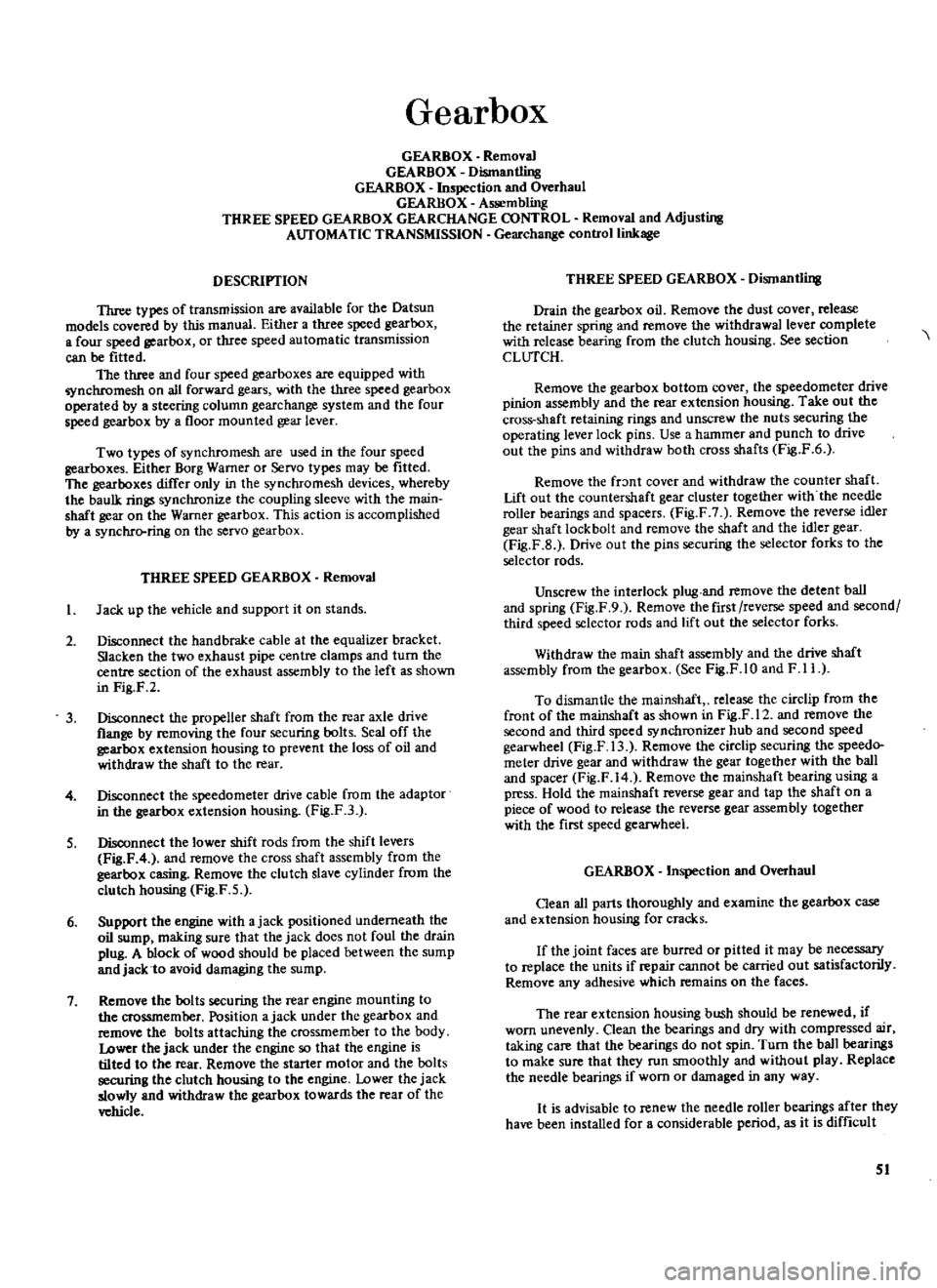
Gearbox
GEARBOX
Removal
GEARBOX
Dismantling
GEARBOX
Inspection
and
Overhaul
GEARBOX
Assembling
THREE
SPEED
GEARBOX
GEARCHANGE
CONTROL
Removal
and
Adjusting
AUTOMATIC
TRANSMISSION
Gearchange
control
linkage
DESCRIPTION
Three
types
of
transmission
are
available
for
the
Datsun
models
covered
by
this
manual
Either
a
three
speed
gearbox
a
four
speed
gearbox
or
three
speed
automatic
transmission
can
be
fitted
The
three
and
four
speed
gearboxes
are
equipped
with
nchromesh
on
all
forward
gears
with
the
three
speed
gearbox
operated
by
a
steering
column
gearchange
system
and
the
four
speed
gearbox
by
a
floor
mounted
gear
lever
Two
types
of
synchromesh
are
used
in
the
four
speed
gearboxes
Either
Borg
Warner
or
Servo
types
may
be
fitted
The
gearboxes
differ
only
in
the
synchromesh
devices
whereby
the
baulk
rings
synchronize
the
coupling
sleeve
with
the
main
shaft
gear
on
the
Warner
gearbox
This
action
is
accomplished
by
a
synchrcrring
on
the
servo
gearbox
THREE
SPEED
GEARBOX
Removal
I
Jack
up
the
vehicle
and
support
it
on
stands
2
Disconnect
the
hand
brake
cable
at
the
equalizer
bracket
Slacken
the
two
exhaust
pipe
centre
clamps
and
turn
the
centre
section
of
the
exhaust
assembly
to
the
left
as
shown
in
Fig
F
2
3
Disconnect
the
propeller
shaft
from
the
rear
axle
drive
flange
by
removing
the
four
securing
bolts
Seal
off
the
gearbox
extension
housing
to
prevent
the
loss
of
oil
and
withdraw
the
shaft
to
the
rear
4
Disconnect
the
speedometer
drive
cable
from
the
adaptor
in
the
gearbox
extension
housing
Fig
F3
S
Disconnect
the
lower
shift
rods
from
the
shift
levers
Fig
F
4
and
remove
the
cross
shaft
assembly
from
the
gearbox
casing
Remove
the
clutch
slave
cylinder
from
the
clutch
housing
Fig
F
5
6
Support
the
engine
with
ajack
positioned
underneath
the
oil
sump
making
sure
that
the
jack
does
not
foul
the
drain
plug
A
block
of
wood
should
be
placed
between
the
sump
and
jack
to
avoid
damaging
the
sump
7
Remove
the
bolts
securing
the
rear
engine
mounting
to
the
crossmember
Position
ajack
under
the
gearbox
and
remove
the
bolts
attaching
the
crossmember
to
the
body
Lower
the
jack
under
the
engine
so
that
the
engine
is
tilted
to
the
rear
Remove
the
starter
motor
and
the
bolts
securing
the
clutch
housing
to
the
engine
Lower
the
jack
slowly
and
withdraw
the
gearbox
towards
the
rear
of
the
vehicle
THREE
SPEED
GEARBOX
Dismantling
Drain
the
gearbox
oil
Remove
the
dust
cover
release
the
retainer
spring
and
remove
the
withdrawal
lever
complete
with
release
bearing
from
the
clutch
housing
See
section
CLUTCH
Remove
the
gearbox
bottom
cover
the
speedometer
drive
pinion
assembly
and
the
rear
extension
housing
Take
out
the
cross
shaft
retaining
rings
and
unscrew
the
nuts
securing
the
operating
lever
lock
pins
Use
a
hammer
and
punch
to
drive
out
the
pins
and
withdraw
both
cross
shafts
Fig
F
6
Remove
the
fr
mt
cover
and
withdraw
the
counter
shaft
Lift
out
the
countersbaft
gear
cluster
together
with
the
needle
roller
bearings
and
spacers
Fig
F
7
Remove
the
reverse
idler
gear
shaft
lock
bolt
and
remove
the
shaft
and
the
idler
gear
Fig
F
B
Drive
out
the
pins
securing
the
selector
forks
to
the
selector
rods
Unscrew
the
interlock
plug
and
remove
the
detent
ball
and
spring
Fig
F
9
Remove
the
first
reverse
speed
and
second
third
speed
selector
rods
and
lift
out
the
selector
forks
Withdraw
the
main
shaft
assembly
and
the
drive
shaft
assembly
from
the
gearbox
See
Fig
F
1O
and
F
11
To
dismantle
the
mainshaft
release
the
circlip
from
the
front
of
the
mainshaft
as
shown
in
Fig
F
12
and
remove
the
second
and
third
speed
synchronizer
hub
and
second
speed
gearwheel
Fig
F
13
Remove
the
circlip
securing
the
speedo
meter
drive
gear
and
withdraw
the
gear
together
with
the
ball
and
spacer
Fig
F
14
Remove
the
mainshaft
bearing
using
a
press
Hold
the
rnainshaft
reverse
gear
and
tap
the
shaft
on
a
piece
of
wood
to
release
the
reverse
gear
assembly
together
with
the
first
speed
gearwheel
GEARBOX
Inspection
and
Overhaul
Oean
all
parts
thoroughly
and
examine
the
gearbox
case
and
extension
housing
for
cracks
If
the
joint
faces
are
burred
or
pitted
it
may
be
necessary
to
replace
the
units
if
repair
cannot
be
carried
out
satisfactorily
Remove
any
adhesive
which
remains
on
the
faces
The
rear
extension
housing
bush
should
be
renewed
if
worn
unevenly
Clean
the
bearings
and
dry
with
compressed
air
taking
care
that
the
bearings
do
not
spin
Turn
the
ball
bearings
to
make
sure
that
they
run
smoothly
and
without
play
Replace
the
needle
bearings
if
worn
or
damaged
in
any
way
It
is
advisable
to
renew
the
needle
roller
bearings
after
they
have
been
installed
for
a
considerable
period
as
it
is
difficult
51
Page 64 of 171
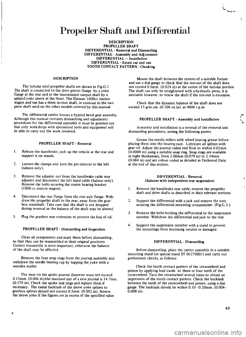
Propeller
Shaft
and
DIfferentIaJ
DESCRIPTION
PROPELLER
SHAFT
DIFFERENTIAL
Removal
and
Dismantling
DIFFERENTIAL
Assembly
and
Adj
Jstment
DIFFERENTIAL
Installation
DIFFERENTIAL
Estate
car
and
van
TOOTH
CONTACT
PATTERN
Checking
DESCRIPTION
The
tubular
steel
propeller
shafts
are
shown
in
Fig
G
1
The
shaft
is
connected
to
the
drive
pinion
flange
by
a
yoke
flange
at
the
rear
and
to
the
transmission
output
shaft
by
a
splined
yoke
sleeve
at
the
front
The
Datsum
I800ce
station
wagon
and
van
has
a
three
section
shaft
in
contrast
to
the
two
piece
shaft
used
on
the
other
models
covered
by
this
manual
The
differential
carrier
houses
a
hypoid
bevel
gear
assembly
Although
this
manual
contains
dismantling
and
adjustment
procedures
for
the
differential
assembly
it
must
be
pointed
out
that
only
workshops
with
specialized
tools
and
equipment
will
be
able
to
carry
out
the
work
involved
PROPELLER
SHAFT
Removal
1
Release
the
hand
brake
jack
up
the
vehicle
at
the
fear
and
support
it
on
stands
2
Loosen
the
clamps
and
turn
the
pre
silencer
to
the
left
saloon
only
3
Remove
the
adjuster
nut
from
the
handbrake
cable
rear
adjuster
and
disconnect
the
left
hand
cable
Saloon
only
Remove
the
bolts
securing
the
centre
bearing
bracket
1800
cc
stati
n
wagon
4
Disconnect
the
fear
flange
from
the
rear
axle
flange
With
draw
the
propeller
shaft
to
the
rear
away
from
the
gear
box
mainshaft
Take
care
that
the
shaft
is
not
dropped
during
removal
or
the
balance
of
the
shaft
may
be
altered
5
Plug
the
gearbox
rear
extension
to
prevent
the
loss
of
oil
PROPELLER
SHAFT
Dismantling
and
Inspection
Oean
all
components
and
mark
them
before
dismantling
so
that
they
can
be
reassembled
in
their
original
positions
Correct
reassembly
is
most
important
otherwise
the
balance
of
the
shaft
may
be
affected
Remove
the
four
snap
rings
from
the
journal
assembly
and
withdraw
the
needle
bearing
cap
by
tapping
the
yoke
with
a
wooden
mallet
The
wear
on
the
spider
journal
diameter
must
not
exceed
0
15mm
0
006
in
the
standard
size
of
a
new
journal
is
14
7mm
0
579
in
Check
the
spider
seal
rings
and
replace
them
if
necessary
The
radial
backlash
of
the
sleeve
yoke
splines
to
gearbox
splines
should
not
exceed
0
5mm
0
002
in
Renew
the
sleeve
yoke
if
the
figures
are
in
excess
of
the
specified
value
E
Mount
the
shaft
between
the
centres
of
a
suitable
fixture
and
use
a
dial
gauge
to
check
that
the
run
out
of
the
shaft
does
not
exceed
0
6mm
0
024
in
at
the
centre
of
the
tubular
portion
The
shaft
can
only
be
straightened
with
a
hydraulic
press
it
is
advisable
however
to
renew
the
shaft
if
the
run
out
is
excessive
Check
that
the
dynamic
balance
of
the
shaft
does
not
exceed
15
grm
cm
0
208
oz
in
at
4000
r
p
m
PROPELLER
SHAFT
Assembly
and
11Istallation
r
Assembly
and
installation
is
a
reversal
of
the
removal
and
dismantling
procedures
not
the
following
points
Grease
the
needle
rollers
with
wheel
bearing
grease
before
placing
them
into
the
bearing
race
Lubricate
all
splines
with
gear
oil
Adjust
the
journal
radial
end
float
to
within
0
02mm
0
0008
in
using
a
suitable
snap
ring
Snap
rings
are
available
in
eight
thicknesses
from
2
00mm
0
079
in
to
2
14mm
0
084
in
and
are
colour
coded
as
detailed
in
Technical
Data
at
the
end
of
this
section
DIFFERENTIAL
Removal
Saloons
with
independent
rear
suspension
Remove
the
hand
brake
rear
cable
remove
the
propeller
shaft
and
drive
shafts
as
described
in
their
relevant
sections
2
Support
the
differential
with
ajack
and
remove
the
nuts
securing
the
differential
mounting
crossmemb
er
Fig
G
3
3
Remove
the
bolts
holding
the
differential
to
the
suspension
member
Withdraw
the
differential
and
jack
to
the
rear
4
Support
the
suspension
member
with
a
stand
to
prevent
the
mountings
from
becoming
twisted
or
damaged
DIFFERENTIAL
Dismantling
Before
dismantling
place
the
carrier
assembly
in
a
suitable
mounting
stand
or
special
stand
ST
06270001
and
carry
out
preliminary
checks
as
follows
Check
the
tooth
contact
pattern
of
the
crownwheel
and
pinion
by
applying
lead
oxide
to
three
or
four
teeth
of
the
crownwheel
Turn
the
crownwheel
several
times
to
obtain
an
impression
of
the
tooth
contact
pattern
Check
the
backlash
between
the
teeth
of
the
crownwheel
and
pinion
using
a
dial
gauge
The
backlash
should
be
within
0
10
0
20mm
0
004
0
008
in
63
Page 70 of 171
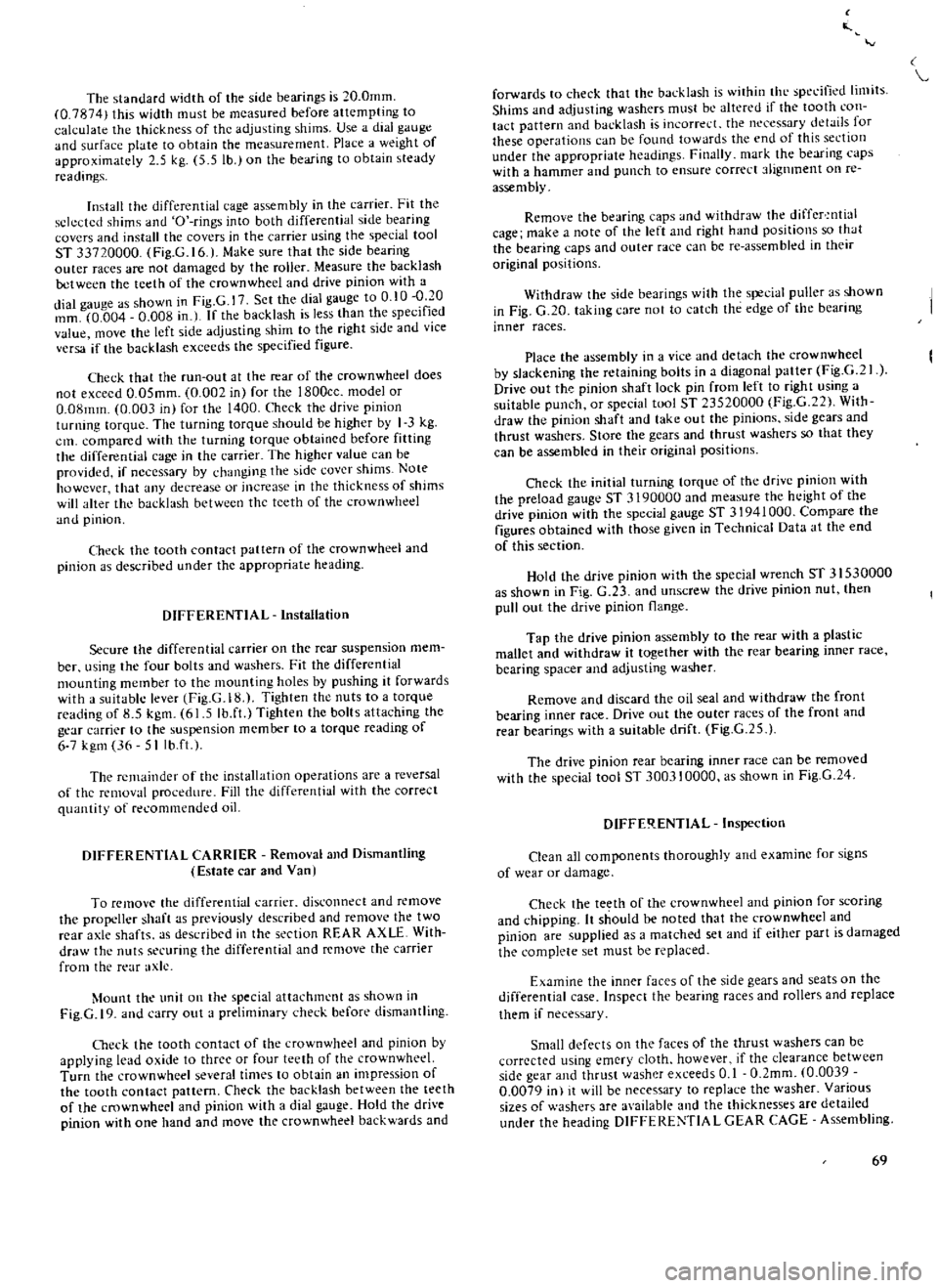
The
standard
width
of
the
side
bearings
is
20
0mm
0
7874
this
width
must
be
measured
before
attempting
to
calculate
the
thickness
of
the
adjusting
shims
Use
a
dial
gauge
and
surface
plate
to
ohtain
the
measurement
Place
a
weight
of
approximately
2
5
kg
5
5
lb
on
the
bearing
to
obtain
steady
readings
Install
the
differential
cage
assembly
in
the
carrier
Fit
the
sckcted
shims
and
O
rings
into
both
differential
side
bearing
covers
and
install
the
covers
in
the
carrier
using
the
special
tool
ST
33720000
Fig
G
16
l
Make
sure
that
the
side
bearing
outer
races
are
not
damaged
by
the
roller
Measure
the
backlash
between
the
teeth
of
the
crown
wheel
and
drive
pinion
with
a
dial
gauge
as
shown
in
Fig
G
I
Sct
the
dial
gauge
to
0
10
f
O
mm
0
004
0
008
in
I
If
the
backlash
is
less
than
the
specifIed
value
move
he
left
side
adjusting
shim
to
the
right
side
and
vice
versa
if
the
backlash
exceeds
the
specified
figure
Check
that
the
run
out
at
the
rear
of
the
crownwheel
does
not
excecd
O
OSmm
0
002
in
for
the
1800ce
model
or
O
08mm
0
003
in
for
the
1400
Check
the
drive
pinion
turning
torque
Thc
turning
torque
should
be
higher
by
I
3
kg
em
compared
with
the
turning
torque
obtained
before
fitting
the
differential
cage
in
the
carrier
The
higher
value
can
be
provided
if
necessary
by
dmnging
the
jde
cover
shims
Note
howcver
that
any
decrease
or
increase
in
the
thickncss
of
shims
wjJl
alter
tht
budlush
between
the
teeth
of
the
crownwhee1
and
pinion
Check
the
tooth
contact
pat
tern
of
the
crown
wheel
and
pinion
as
described
under
the
appropriate
heading
DIFFERENTIAL
Installation
Secure
the
differential
carrier
on
the
rear
suspension
mem
ber
using
the
four
bolts
and
washers
Fit
the
differential
mounting
member
to
thc
mounting
holes
by
pushing
it
forwards
with
a
suitable
lever
Fig
G
18
Tighten
the
nuts
to
a
torque
reading
of
8
5
kgm
61
5
Ib
ft
Tighten
the
bolts
attaching
the
gear
carrier
to
the
suspension
member
to
a
torque
reading
of
6
7
kg
36
5Ilb
ft
t
The
rcmainder
of
the
installation
operations
are
a
reversal
of
thc
removal
procedure
Fill
the
differential
with
the
correct
quantity
of
recommended
oil
DIFFERENTIAL
CARRIER
Removal
and
Dismantling
Estate
car
alld
Vanl
To
remove
the
differential
carrier
disconnect
and
remove
rhe
propeller
shaft
as
previously
described
and
remove
the
two
rear
axle
shafts
as
described
in
the
section
REAR
AXLL
With
draw
the
nuts
securing
the
differential
and
remove
the
carrier
from
the
rear
axle
Mount
the
unit
on
the
special
attachment
as
shown
in
Fig
G
19
and
carry
out
a
preliminary
check
before
dismantling
Oleck
the
tooth
contact
of
the
crownwheel
and
pinion
by
applying
lead
oxide
to
three
or
four
teeth
of
the
crownwheel
Turn
the
crown
wheel
several
times
to
obtain
an
impression
of
the
tooth
contact
pattern
Check
the
backlash
between
the
teeth
of
the
crownwheel
and
pinion
with
a
dial
gauge
Hold
the
drive
pinion
with
one
hand
and
move
the
crown
wheel
backwards
and
forwards
to
check
that
the
backlash
is
Io
ithin
thL
speL
ified
limits
Shims
and
adjusting
washers
must
bL
altered
if
the
tooth
con
tact
pattern
and
backlash
is
incorre
L
the
neL
cssary
details
for
these
operations
can
be
found
towards
the
end
of
this
section
under
the
appropriate
he
Jdjn
s
Fil1JJly
mark
the
bearing
caps
with
a
hammer
and
punch
to
ensure
correct
t1ignment
on
re
assembly
Remove
the
bearing
caps
nd
withdraw
the
differ
ntial
cage
make
a
note
of
the
left
and
right
hand
positions
so
h
Jt
the
bearing
caps
and
outer
race
can
be
re
assembled
in
their
original
positions
Withdraw
the
side
beJrings
with
the
s
cjal
puller
as
shown
in
Fig
G
20
taking
care
not
to
catch
the
edge
of
the
bearing
inner
races
Place
the
assembly
in
a
vice
and
detach
the
crownwheel
by
slackening
the
retaining
bolts
in
a
diagonal
patter
Fig
G
lf
Drive
out
th
pinion
shaft
lock
pin
from
left
to
right
using
a
suitable
punch
or
special
tool
ST
23520000
Fig
C
22
With
draw
the
pinion
shaft
and
take
out
the
pinions
side
gears
and
thrust
washers
Store
the
gears
and
thrust
washers
so
that
they
can
be
assembled
in
their
original
positions
Check
the
initial
turning
torque
of
the
drive
pinion
with
the
preload
gauge
ST
3190000
and
measure
the
height
of
the
drive
pinion
with
the
special
gauge
ST
31941000
Compare
the
figures
obtained
with
those
givcn
in
Technical
Data
at
the
end
of
this
section
Hold
the
drive
pinion
with
the
speciaJ
wrench
ST
3
J
530000
as
shown
in
Fig
C
23
and
unscrew
the
drivc
pinion
nut
then
pull
out
the
drive
pjnion
flange
Tap
the
drive
pinion
assembly
to
the
rear
with
a
plastic
mallet
and
withdraw
it
together
with
the
rear
bearing
inner
race
bearing
spacer
and
adjusting
washer
Remove
and
discard
the
oil
seal
and
withdraw
thc
front
bearing
inner
race
Drive
out
the
outer
races
of
the
front
and
rear
bearings
with
a
suitable
drift
Fig
G
25
The
drive
pinion
rear
bearing
inncr
race
can
be
removed
with
the
special
tool
ST
300310000
as
shown
in
Fig
G
24
DIFFE
l
ENTlAL
Inspection
Clean
all
components
thoroughly
and
examine
for
signs
of
wear
or
damage
Check
the
teeth
of
the
crownwhcel
and
pinion
for
scoring
and
hipping
Ii
should
be
noted
that
the
crownwhecl
and
pinion
are
supplied
as
a
matched
set
and
if
either
part
is
damaged
the
complete
set
must
be
replaced
Examine
the
inner
faces
of
the
side
gears
and
seats
on
the
differential
case
Inspect
the
bearing
races
and
rollers
and
replace
them
if
necessary
Small
defects
on
the
faces
of
the
thrust
washers
can
be
corrected
using
emery
cloth
however
if
the
clearance
between
side
gear
and
thrust
washer
exceeds
0
1
O
2mm
0
0039
0
0079
in
it
ill
be
necessary
to
replace
the
washer
Various
sizes
of
washers
are
available
and
the
thicknesses
arc
detailed
under
the
heading
DIFFERENTIA
L
GEAR
CAGE
Assembling
69
Page 99 of 171
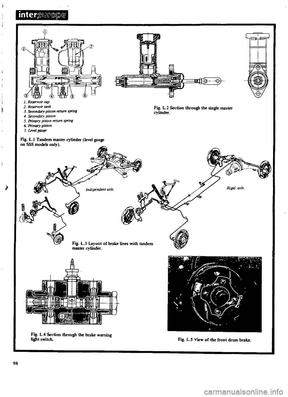
inter
G
@lfi
r
OIl
ll
V
V
1
Re
rvoir
azp
2
Resovoir
tank
3
condDry
piston
rrtrun
rprins
4
Secondary
pitton
5
Primary
piston
tum
spring
6
Primary
piston
7
uvd
gau
Fl
L
I
Tandem
master
cylinder
level
gauge
on
SSS
models
only
Fig
L
2
Section
through
the
single
master
cylinder
I
Independent
axle
Rigid
axle
Fig
L
3
Layout
of
brake
lines
with
tandem
master
cylinder
A
Ji
I
I
f
tf
A1
r
Fig
L
4
Section
through
the
brake
warning
light
switch
Fl
L
5
View
of
the
front
drum
brake
98
Page 147 of 171
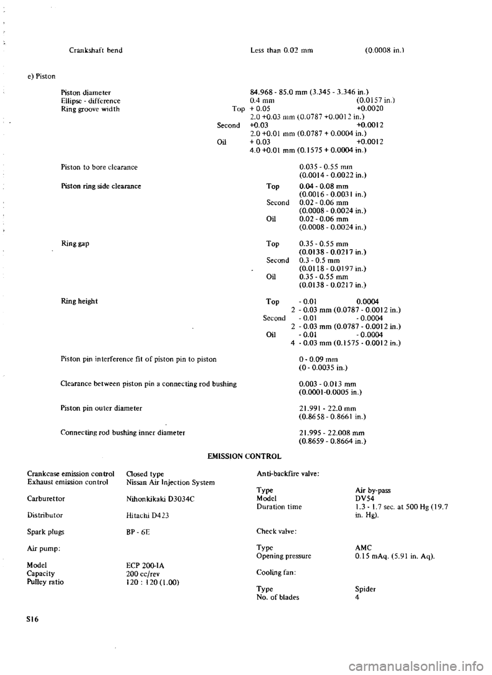
Crank
shaf
bend
Less
than
0
02
mm
0
0008
in
e
Piston
Pis
on
diameter
Ellipse
difference
Ring
groove
wid
h
84
968
85
0
mm
3
345
3
346
in
0
4
mm
0
01
7
in
Top
0
05
0
0020
0
0
03
mm
0
0787
0
001
in
Second
I
03
0
0012
2
0
0
01
mm
0
0787
0
0004
in
Oil
0
03
0
0012
4
0
0
01
mm
0
1575
0
0004
in
Piston
ring
side
clearance
0
035
0
55
mm
0
0014
0
0022
in
Top
0
04
0
08
mID
0
0016
0
0031
in
Second
0
02
0
06
mm
0
0008
0
0024
in
Oil
0
02
0
06
mm
0
0008
0
0024
in
Piston
to
bore
clearance
Ring
gap
Top
0
35
0
55
mm
0
0138
0
0217
in
Second
0
3
0
5
mm
0
0118
0
0197
in
Oil
0
35
0
55
mm
0
0138
0
0217
in
Top
0
01
0
0004
2
0
03
mm
0
0787
0
0012
in
Second
0
01
0
0004
2
0
03
mm
0
0787
0
0012
in
Oil
0
Q1
0
0004
4
0
03mm
0
I575
0
0012in
Ring
height
Piston
pin
interferenl
c
fit
of
piston
pin
to
piston
o
0
09
mm
0
0
0035
in
0
003
0
013
mm
0
0001
0
0005
in
Clearance
between
piston
pin
a
connecting
rod
bushing
Piston
pin
outer
diameter
21
991
22
0
mm
0
8658
0
8661
in
Connecting
rod
bushing
inner
diameter
21
995
22
008
mm
0
8659
0
8664
in
EMISSION
CONTROL
Crankcase
emission
con
trol
Closed
type
Exhaust
emiision
control
Nissan
Air
Injec
ion
System
Anti
backIrre
valve
Carburettor
Nihonkikaki
D3034C
Type
Model
Duration
time
Air
by
pass
DV54
1
3
L7
sec
at
500
Hg
9
7
in
Hg
Distribu
or
Hitachi
D423
Spark
plugs
BP
6E
Check
valve
Air
pump
Type
Opening
pressure
AMC
0
15
mAq
5
91
in
Aq
Model
Capacity
Pulley
ratio
ECP
20Q
IA
200
cc
rev
120
120
1
00
Cooling
fan
Type
No
of
blades
Spider
4
S16