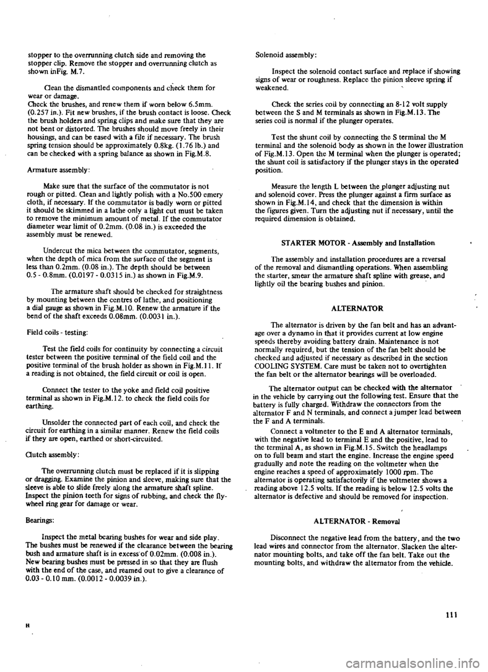
headlamp DATSUN 610 1969 Workshop Manual
[x] Cancel search | Manufacturer: DATSUN, Model Year: 1969, Model line: 610, Model: DATSUN 610 1969Pages: 171, PDF Size: 10.63 MB
Page 112 of 171

stopper
to
the
overrunning
clutch
side
and
removing
the
stopper
clip
Remove
the
stopper
and
overrunning
clutch
as
shown
inFig
M
7
Oean
the
dismantled
components
and
check
them
for
wear
or
damage
Cbeck
the
brushes
and
renew
them
if
worn
below
6
5mm
0
257
in
Fit
new
brushes
if
the
brush
contact
is
loose
Cbeck
the
brush
holders
and
spring
clips
and
make
sure
that
they
are
not
bent
or
distorted
The
brushes
should
move
freely
in
their
housings
and
can
be
eased
with
a
file
if
necessary
The
brush
spring
tension
should
be
approximately
0
8kg
1
76Ib
and
can
be
checked
with
a
spring
balance
as
shown
in
Fig
M
S
Armature
assembly
Make
sure
that
the
surface
of
the
commutator
is
not
rough
or
pitted
Oean
and
lightly
polish
with
a
No
500
emery
cloth
if
necessary
If
the
commutator
is
badly
worn
or
pitted
it
should
be
skimmed
in
a
lathe
only
a
light
cut
must
be
taken
to
remove
the
minimum
amount
of
metal
If
the
commutator
diameter
wear
limit
of
0
2mm
0
OS
in
is
exceeded
the
assembly
must
be
renewed
Undercut
the
mica
between
the
commutator
segments
when
the
depth
of
mica
from
the
surface
of
the
segment
is
less
than
0
2mm
0
08
in
The
depth
should
be
between
0
5
0
8mm
0
0197
0
0315
in
as
shown
in
Fig
M
9
The
armature
shaft
should
be
checked
for
straightness
by
mounting
between
the
centres
of
lathe
and
positioning
a
dial
gauge
as
shown
in
Fig
M
I
O
Renew
the
armature
if
the
bend
of
the
shaft
exceeds
0
08mm
0
0031
in
Field
coils
testing
Test
the
field
coils
for
continuity
by
connecting
a
circuit
tester
between
the
positive
terminal
of
the
field
coil
and
the
positive
terminal
of
the
brush
holder
as
shown
in
Fig
M
I
I
If
a
reading
is
not
obtained
the
field
circuit
or
coil
is
open
Cbnnect
the
tester
to
the
yoke
and
field
coil
positive
teoninal
as
shown
in
Fig
M
12
to
check
the
field
coils
for
earthing
Unsolder
the
connected
part
of
each
coil
and
check
the
circuit
for
earthing
in
a
similar
manner
Renew
the
field
coils
if
they
are
open
earthed
or
short
circuited
Outch
assembly
The
overrunning
clutch
must
be
replaced
if
it
is
slipping
or
dragging
Examine
the
pinion
and
sleeve
making
sure
that
the
sleeve
is
able
to
slide
freely
along
the
armature
shaft
spline
Inspect
the
pinion
teeth
for
signs
of
rubbing
and
check
the
fly
wheel
ring
gear
for
damage
or
wear
Bearings
Inspect
the
metal
bearing
bushes
for
wear
and
side
play
The
bushes
must
be
renewed
if
the
clearance
between
the
bearing
bush
and
armature
shaft
is
in
excess
of
0
02mm
0
008
in
New
bearing
bushes
must
be
pressed
in
so
that
they
are
flush
with
the
end
of
the
case
and
reamed
ou
t
to
give
a
clearance
of
0
03
0
10
mm
0
0012
0
0039
in
H
Solenoid
assembly
Inspect
the
solenoid
contact
surface
and
replace
if
showing
signs
of
wear
or
roughness
Replace
the
pinion
sleeve
spring
if
weakened
Check
the
series
coil
by
connecting
an
8
12
volt
supply
between
the
Sand
M
terminals
as
shown
in
Fig
M
13
The
series
coil
is
normal
if
the
plunger
operates
Test
the
shunt
coil
by
connecting
the
S
terminal
the
M
terminal
and
the
solenoid
body
as
shown
in
the
lower
illustration
of
Fig
M
13
Open
the
M
terminal
when
the
plunger
is
operated
the
shunt
coil
is
satisfactory
if
the
plunger
stays
in
the
operated
position
Measure
the
length
L
between
theylonger
adjusting
nut
and
solenoid
cover
Press
the
plunger
against
a
firm
surface
as
shown
in
Fig
M
14
and
check
that
the
dimension
is
within
the
figures
given
Turn
the
adjusting
nut
if
necessary
until
the
required
dimension
is
obtained
STARTER
MOTOR
Assembly
and
Installation
The
assembly
and
installation
procedures
are
a
reversal
of
the
removal
and
dismantling
operations
When
assembling
the
starter
smear
the
armature
shaft
spline
with
grease
and
lightly
oil
the
bearing
bushes
and
pinion
ALTERNATOR
The
alternator
is
driven
by
the
fan
belt
and
has
an
advant
age
over
a
dynamo
in
that
it
provides
current
at
low
engine
speeds
thereby
avoiding
battery
drain
Maintenance
is
not
normally
required
but
the
tension
of
the
fan
belt
should
be
checked
and
adjusted
if
necessary
as
described
in
the
section
COOLING
SYSTEM
Care
must
be
taken
not
to
overtighten
the
fan
belt
or
the
alternator
bearings
will
be
overloaded
The
alternator
output
can
be
checked
with
the
alternator
in
the
vehicle
by
carrying
out
the
following
test
Ensure
that
the
battery
is
fully
charged
Withdraw
the
connectors
from
the
alternator
F
and
N
terminals
and
connect
a
jumper
lead
between
the
F
and
A
terminals
Connect
a
voltmeter
to
the
E
and
A
alternator
terminals
with
the
negative
lead
to
terminal
E
and
the
positive
lead
to
the
terminal
A
as
shown
in
Fig
M
IS
Switch
the
headlamps
on
to
full
beam
and
start
the
engine
Increase
the
engine
speed
gradually
and
note
the
reading
on
the
voltmeter
when
the
engine
reaches
a
speed
of
approximately
lOaD
rpm
The
alternator
is
operating
satisfactorily
if
the
voltmeter
shows
a
reading
above
12
5
volts
If
the
reading
is
below
12
5
volts
the
alternator
is
defective
and
should
be
removed
for
inspection
ALTERNATOR
Removal
Disconnect
the
negative
lead
from
the
battery
and
the
two
lead
wires
and
connector
from
the
alternator
Slacken
the
alter
nator
mounting
bolts
and
take
off
the
fan
belt
Take
out
the
mounting
bolts
and
withdraw
the
alternator
from
the
vehicle
III
Page 115 of 171

inter
ill
1
@
fl@
2mm
O
07e7
in
l
r
Fig
M
27
Measuring
the
brush
spring
pressure
oo
fI
f
Fig
M
29
R
h
the
headlamp
Ied
beam
AMM
E
iER
HO
to
SA
HO
N
SWITCH
1
VOLTMETER
115
to
2OV
I
I
Fig
M
31
Testing
and
adjusting
the
horn
114
J
GJ
Fig
M
28
Tightening
the
puUey
nut
HORN
RELAY
L
IBGIGY
tt
t
e
q
HO
N
r
FUSIBLE
LINK
IO
e5
REO
FUS
E
BOX
20A
El
Sl
I
10
STOP
LAMP
SWITCH
HORN
eu
TTON
eATT
RY
Fig
M
JO
Circuit
diagram
for
the
horn
system
Fig
M
32
Adjusting
the
horn
volume
and
tone
Page 116 of 171

ALTERNATOR
Dismantling
Refening
to
Fig
M
16
remove
the
pulley
nut
and
take
off
the
pulley
rim
fan
and
spacer
Withdraw
the
brush
holder
retaining
screws
and
remove
the
brush
holder
cover
Withdraw
the
holder
and
brushes
as
shown
in
Fig
M
17
Slacken
and
remove
the
three
through
bolts
and
separate
the
diode
housing
from
the
drive
end
housing
by
tapping
the
front
bracket
lightly
with
a
wooden
mallet
Fig
M
18
Remove
the
screws
from
the
bearing
retainer
and
separate
the
rotor
from
the
front
cover
Fig
M
19
Remove
the
rear
bearing
from
the
rotor
assembly
with
the
aid
of
a
puller
as
shown
in
Fig
M
2D
Take
off
the
diode
cover
and
unsolder
the
three
stator
coil
lead
wires
from
the
diode
terminal
Remove
the
A
terminal
nut
and
diode
installation
nut
and
remove
the
diode
assembly
Do
not
force
the
diode
assembly
when
removing
or
it
may
be
damaged
Remove
the
stator
from
the
rear
cover
ALTERNATOR
Inspection
Use
an
ohmmeter
as
shown
in
Fig
M
21
to
test
the
rotor
field
coil
Apply
the
tester
between
the
slip
rings
and
check
that
the
resistance
is
approximately
4
4
ohms
at
normal
ambient
temperature
Check
the
conductivity
between
slip
ring
and
rotor
core
as
shown
in
Fig
M
22
if
conductivity
exists
the
field
coil
or
slip
ring
must
be
earthing
and
the
rotor
assembly
should
be
renewed
Cbeck
the
stator
to
ensure
that
there
is
conductivity
retween
the
individual
stator
coil
terminals
as
shown
in
Fig
M
23
If
there
is
no
conductivity
between
the
individual
terminals
the
stator
is
defective
Check
each
lead
wire
including
the
neutral
wire
as
shown
in
Fig
M
24
If
there
is
conductivity
between
any
wire
and
the
stator
COTe
the
stator
core
is
earthing
and
the
stator
must
be
replaced
Diodes
Three
positive
diodes
are
mounted
on
the
positive
plate
and
three
negative
diodes
are
mounted
on
the
negative
plate
The
diodes
allow
current
to
flow
in
one
direction
only
The
diodes
on
the
positive
plate
only
allow
current
to
flow
from
the
terminal
to
the
positive
plate
whilst
the
diodes
on
the
negative
plate
only
allow
current
to
flow
from
the
negative
plate
to
the
terminal
A
diode
which
allows
current
to
flow
in
ooth
directions
or
does
not
allow
current
to
flow
in
the
correct
direction
is
unserviceable
and
all
six
diodes
must
be
replaced
Use
a
tester
as
shown
in
Figs
M
25
and
M26
to
check
each
diode
Brushes
Check
the
movement
of
the
brushes
in
their
holders
The
brushes
should
move
freely
and
can
be
eased
in
necessary
by
carefully
ming
the
sides
Oean
the
brush
holders
before
replacing
the
brushes
Renew
the
brushes
if
they
are
worn
below
a
length
of
7mm
0
275
in
With
the
brush
projecting
approximately
2mm
0
08
in
from
the
holder
it
is
possible
to
measure
the
brush
spring
pressure
using
a
spring
balance
as
shown
in
Fig
M
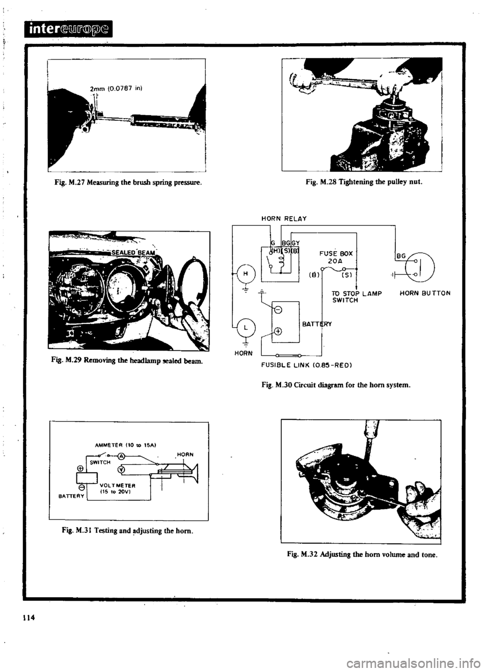
27
The
pressure
of
a
new
brush
should
be
255
345
grammes
9
0
12
2
oz
the
pressure
will
however
decrease
by
approxi
mately
20
grammes
per
I
amm
0
039
in
of
wear
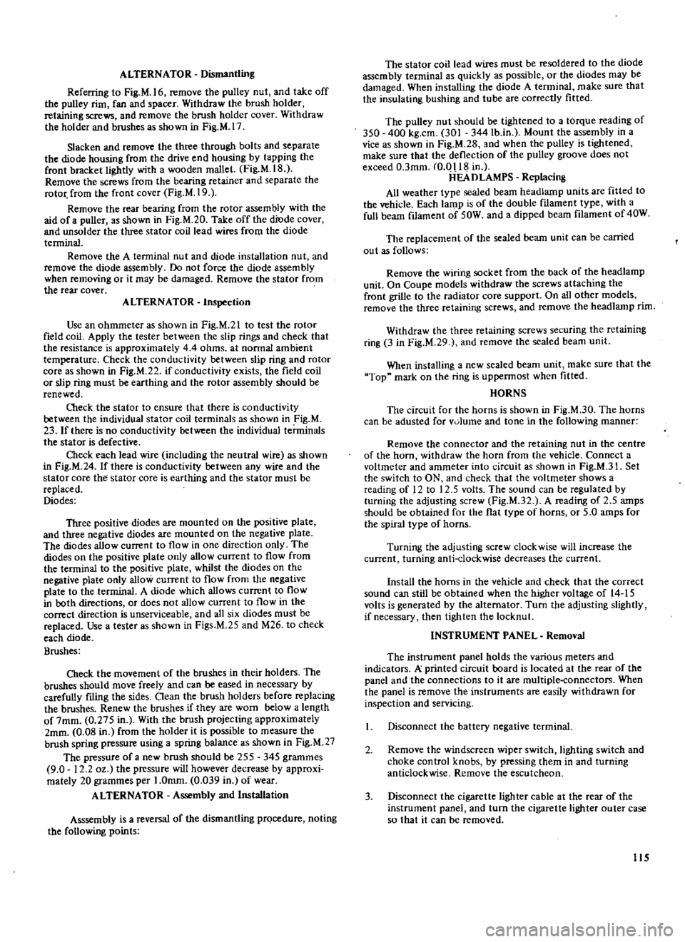
ALTERNATOR
Assembly
and
Installation
Asssembly
is
a
reversal
of
the
dismantling
prQcedure
noting
the
following
points
The
stator
coil
lead
wires
must
be
resoldered
to
the
diode
assembly
terminal
as
quickly
as
possible
or
the
diodes
may
be
damaged
When
installing
the
diode
A
tenninal
make
sure
that
the
insulating
bushing
and
tube
are
correctly
fitted
The
pulley
nut
should
he
tightened
to
a
torque
reading
of
350
400
kg
cm
301
344Ib
in
Mount
the
assembly
in
a
vice
as
shown
in
Fig
M
28
and
when
the
pulley
is
tightened
make
sure
that
the
deflection
of
the
pulley
groove
does
not
exceed
O
3mm
m
o
118
in
ilEA
D
LAMPS
Replacing
All
weather
type
sealed
beam
headlamp
units
are
fitted
to
the
vehicle
Each
lamp
is
of
the
double
fIlament
type
with
a
full
beam
filament
of
50W
and
a
dipped
beam
filament
of
40W
The
replacement
of
the
sealed
beam
unit
can
be
carried
out
as
follows
Remove
the
wiring
socket
from
the
back
of
the
headlamp
unit
On
Coupe
models
withdraw
the
screws
attaching
the
front
grille
to
the
radiator
core
support
On
all
other
models
remove
the
three
retaining
screws
and
remove
the
headlamp
rim
Withdraw
the
three
retaining
screws
securing
the
retaining
ring
3
in
Fig
M
29
and
remove
the
sealed
beam
unit
When
installing
a
new
sealed
beam
unit
make
sure
that
the
Top
mark
on
the
ring
is
uppennost
when
fitted
HORNS
The
circuit
for
the
horns
is
shown
in
Fig
M
30
The
horns
can
be
adusted
for
v01ume
and
tone
in
the
following
manner
Remove
the
connector
and
the
retaining
nut
in
the
centre
of
the
horn
withdraw
the
horn
from
the
vehicle
Connect
a
voltmeter
and
ammeter
into
circuit
as
shown
in
Fig
M
3I
Set
the
switch
to
ON
and
check
that
the
voltmeter
shows
a
reading
of
12
to
12
5
volts
The
sound
can
be
regulated
by
turning
the
adjusting
screw
Fig
M
32
A
reading
of
2
5
amps
should
be
obtained
for
the
flat
type
of
horns
or
5
0
amps
for
the
spiral
type
of
horns
Turning
the
adjusting
screw
clockwise
will
increase
the
current
turning
anti
clockwise
decreases
the
current
Install
the
horns
in
the
vehicle
and
check
that
the
correct
sound
can
still
be
obtained
when
the
higher
voltage
of
14
15
volts
is
generated
by
the
alternator
Turn
the
adjusting
slightly
if
necessary
then
tighten
the
locknut
INSTRUMENT
PANEL
Removal
The
instrument
panel
holds
the
various
meters
and
indicators
A
printed
circuit
board
is
located
at
the
rear
of
the
panel
and
the
connections
to
it
are
multiple
connectors
When
the
panel
is
remove
the
instruments
are
easily
withdrawn
for
inspection
and
servicing
Disconnect
the
battery
negative
terminal
2
Remove
the
windscreen
wiper
switch
lighting
switch
and
choke
control
knobs
by
pressing
them
in
and
turning
anticlockwise
Remove
the
escutcheon
3
Disconnect
the
cigarette
lighter
cable
at
the
rear
of
the
instrument
panel
and
turn
the
cigarette
lighter
outer
case
so
that
it
can
be
removed
115
Page 170 of 171

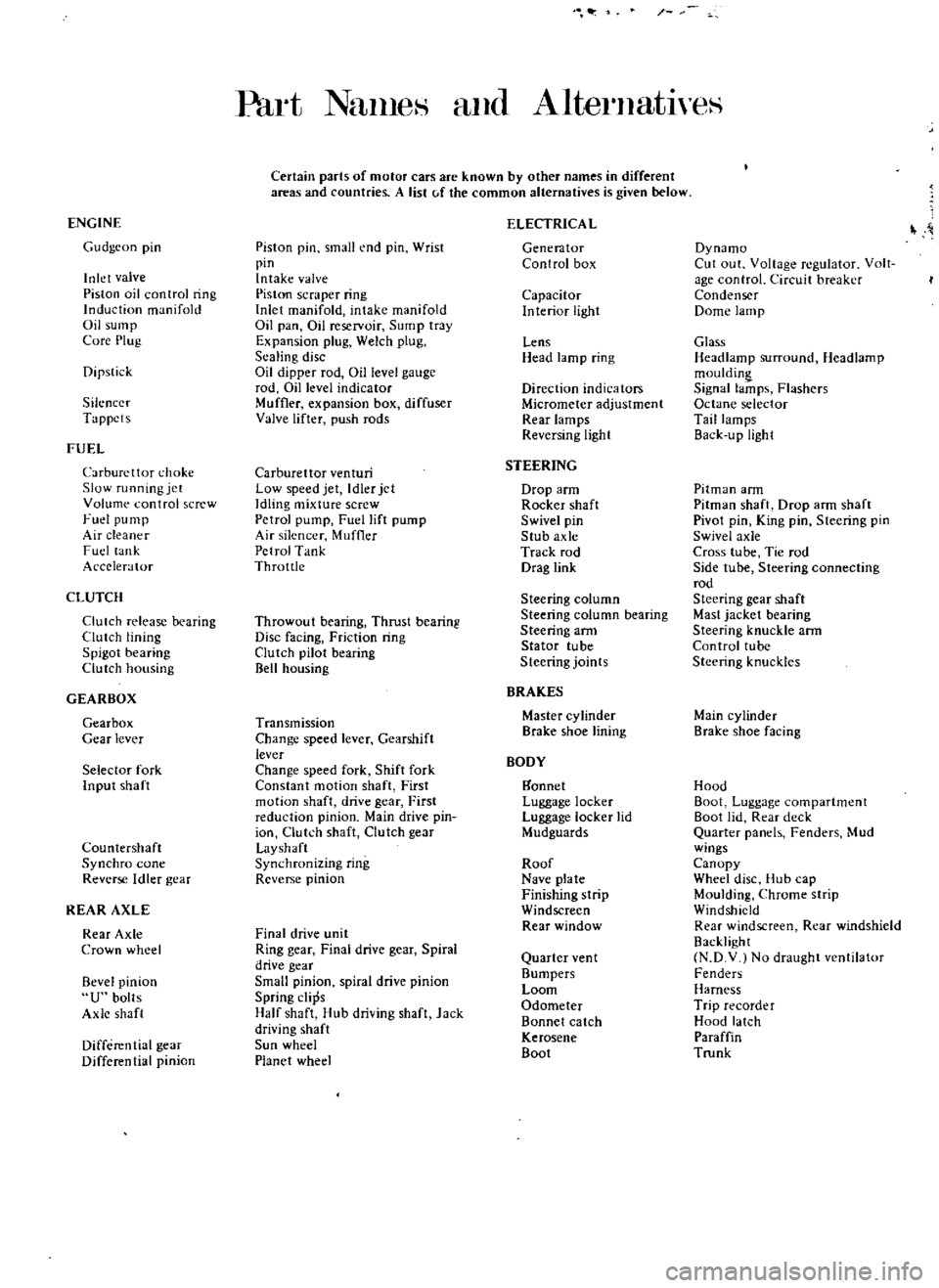
Part
NanleH
and
AlternatlyeS
Certain
parts
of
motor
cars
are
known
by
other
names
in
different
areas
and
countries
A
list
c
f
the
common
alternatives
is
given
below
ENGINE
ELECTRICA
L
Gudgeon
pin
Piston
pin
small
end
pin
Wrist
Generator
Dynamo
pin
Control
box
Cut
out
Voltage
regulator
Volt
Inlet
valve
Intake
valve
age
control
Circuit
breaker
Piston
oil
control
ring
Piston
scraper
ring
Capacitor
Condenser
Induction
manifold
Inlet
manifold
intake
manifold
Interior
light
Dome
lamp
Oil
sump
Oil
pan
Oil
reservoir
Sump
tray
Core
Plug
Expansion
plug
Welch
plug
Lens
Glass
Sealing
disc
Head
lamp
ring
Headlamp
surround
Headlamp
Dipstick
Oil
dipper
rod
Oil
level
gauge
mouldin
rod
Dillevel
indicator
Direction
indicators
Signal
lamps
Flashers
Silencer
Muffler
expansion
box
diffuser
Micrometer
adjustment
Octane
selector
Tappets
Valve
lifter
push
rods
Rear
lamps
Tail
lamps
Reversing
light
Back
u
pUgh
t
FUEL
Carburettor
choke
Carburettor
venturi
STEERING
Slow
running
jet
Low
speed
jet
Idler
jet
Drop
arm
Pitman
ann
Volume
control
screw
Idling
mixture
screw
Rocker
shaft
Pitman
shaft
Drop
ann
shaft
Fuel
pump
Petrol
pump
Fuel
lift
pump
Swivel
pin
Pivot
pin
King
pin
Steering
pin
Air
cleaner
Air
silencer
Muffler
Stub
axle
Swivel
axle
Fuel
lank
Petrol
Tank
Track
rod
Cross
tube
Tie
rod
Accelerator
Throttle
Drag
link
Side
tube
Steering
connecting
rod
CLUTCH
Steering
column
Steering
gear
shaft
Clutch
release
bearing
Throwout
bearing
Thrust
bearing
Steering
column
bearing
Mast
jacket
bearing
Clutch
lining
Disc
facing
Friction
ring
Steering
arm
Steering
knuckle
ann
Spigot
bearing
Clutch
pilot
bearing
Stator
tube
Control
tube
Clutch
housing
Bell
housing
Steering
joints
Steering
knuckles
GEARBOX
BRAKES
Gearbox
Transmission
Master
cylinder
Main
cylinder
Gear
lever
Change
speed
lever
Gearshift
Brake
shoe
lining
Brake
shoe
facing
lever
BODY
Selector
fork
Change
speed
fork
Shift
fork
Input
shaft
Constant
motion
shaft
First
gannet
Hood
motion
shaft
drive
gear
First
Luggage
locker
Boot
Luggage
compartment
reduction
pinion
Main
drive
pin
Luggage
locker
lid
Boot
lid
Rear
deck
ion
Clutch
shaft
Clutch
gear
Mudguards
Quarter
panels
Fenders
Mud
Countershaft
Layshaft
wings
Synchro
cone
Synchronizing
ring
Roof
Canopy
Reverse
Idler
gear
Reverse
pinion
Nave
plate
Wheel
disc
Hub
cap
Finishing
strip
Moulding
Chrome
strip
REAR
AXLE
Windscreen
Windshield
Rear
Axle
Final
drive
unit
Rear
window
Rear
windscreen
Rear
windshield
Crown
wheel
Ring
gear
Final
drive
gear
Spiral
Backlight
drive
gear
Quarter
ven
t
N
D
V
No
draught
ventilator
Bevel
pinion
Small
pinion
spiral
drive
pinion
Bumpers
Fenders
Loom
Harness
U
bolts
Spring
clips
Odometer
Trip
recorder
Axle
shaft
Half
shaft
Hub
driving
shaft
Jack
Bonnet
catch
Hood
latch
driving
shaft
Kerosene
Paraffin
Differential
gear
Sun
wheel
Boot
Trunk
Differential
pinion
Planet
wheel