height adjustment DATSUN 610 1969 Workshop Manual
[x] Cancel search | Manufacturer: DATSUN, Model Year: 1969, Model line: 610, Model: DATSUN 610 1969Pages: 171, PDF Size: 10.63 MB
Page 18 of 171
h
W
and
connecting
rod
assemblies
Use
a
piston
ring
compressor
to
install
the
pistons
through
the
top
of
the
cylbder
bore
Make
sure
that
the
pistons
and
rings
and
the
cylinder
bores
are
lubricated
with
clean
engine
oil
The
pistons
should
be
arranged
so
that
the
F
mark
faces
to
the
front
and
with
the
piston
ring
gaps
positioned
at
1800
to
each
other
Each
piston
must
be
refitted
into
its
original
bore
NOTE
Single
inlet
valve
springs
are
used
on
the
1400
cc
engine
double
valve
springs
are
used
on
the
1600cc
and
1800
cc
engines
Screw
the
valve
rocker
pivots
with
the
locknuts
into
the
pivot
bushing
Set
the
camshaft
locating
plate
and
install
the
camshaft
in
the
cylinder
head
with
the
groove
in
the
locating
plate
directed
to
the
front
of
the
engine
Install
the
camshaft
sprocket
and
tighten
it
together
with
the
fuel
pump
earn
to
a
torque
reading
of
12
16
kgm
86
116
IbJt
a
eck
that
the
camshaft
end
play
is
within
the
specified
limits
Install
the
rocker
arms
using
a
screwdriver
to
press
down
the
valve
springs
and
fit
the
valve
rocker
springs
Gean
the
joint
faces
of
the
cylinder
block
and
head
thoroughly
before
installing
the
cylinder
head
Turn
the
crank
shaft
until
the
No
1
piston
is
at
T
D
C
on
its
compression
stroke
and
make
sure
that
the
camshaft
sprocket
notch
and
the
oblong
groove
in
the
locating
plate
are
correctly
positioned
Care
should
be
taken
to
ensure
that
the
valves
are
clear
from
the
heads
of
the
pistons
The
crankshaft
and
camshaft
must
not
be
rotated
separately
or
the
valves
will
strike
the
heads
of
the
pistons
Temporarily
tighten
the
two
cylinder
head
bolts
1
and
2
in
Fig
A
37
to
a
torque
reading
of
2
kgm
14
5
lb
ft
Fit
the
crankshaft
sprocket
and
distributor
drive
gear
and
install
the
oil
thrower
Ensure
that
the
mating
marks
on
the
crankshaft
sprocket
face
towards
the
front
Install
the
timing
chain
making
sure
that
the
crankshaft
and
camshaft
keys
are
XJinting
upwards
The
marks
on
the
timing
chain
must
be
aligned
with
the
marks
on
the
right
hand
side
of
the
crankshaft
and
camshaft
sprockets
It
should
be
noted
that
three
location
holes
are
provided
in
the
camshaft
sprocket
See
Fig
A
38
The
camshaft
sprocket
being
set
to
the
No
2
location
hole
by
the
manufacturers
A
stretched
chain
will
however
affect
the
valve
timing
and
if
this
occurs
it
will
be
necessary
to
set
the
camshaft
to
the
No
3
location
hole
in
the
camshaft
sprocket
The
chain
can
be
checked
by
turning
the
engine
until
the
No
1
piston
is
at
T
D
C
on
its
compression
stroke
In
this
position
adjustment
will
be
required
if
the
location
notch
on
the
camshaft
sprocket
is
to
the
left
of
the
groove
on
the
camshaft
locating
plate
as
shown
in
the
illustration
The
correction
is
made
by
setting
the
camshaft
on
the
No
3
location
hole
in
the
camshaft
sprocket
the
No
3
notch
should
then
be
to
the
right
of
the
groove
and
the
valve
timing
will
have
to
be
set
using
the
No
3
timing
mark
Install
the
chain
guide
and
chain
tensioner
when
the
chain
is
located
correctly
There
should
be
no
protrusion
of
the
chain
tensioner
spindle
See
Fig
A
39
A
new
tensioner
must
be
fitted
if
the
spindle
protrudes
Press
a
new
oil
seal
into
the
timing
cover
and
fit
the
cover
into
position
using
a
new
gasket
Apply
sealing
compound
to
the
front
of
the
cylinder
block
and
to
the
gasket
and
to
the
top
of
the
timing
cover
Ensure
that
the
difference
in
height
between
the
top
of
the
timing
cover
and
the
upper
face
of
the
cylinder
block
does
not
exceed
0
15
mm
0
006
in
Two
sizes
of
timing
cover
bolts
are
used
the
size
M8
0
315
in
must
be
tightened
to
a
torque
reading
of
1
0
1
6
kgm
7
2
17
Ib
ft
and
the
size
M6
0
236
in
to
a
torque
reading
of
0
4
0
8
kgm
2
9
81b
ft
Install
the
crankshaft
pulley
and
water
pump
tighten
the
pulley
nut
to
a
torque
reading
of
12
16
kgm
86
8
115
7Ib
ft
then
set
the
No
1
piston
at
T
D
C
on
its
compression
stroke
Finally
tighten
the
cylinder
head
bolts
to
the
specified
torque
reading
in
accordance
with
the
tightening
sequence
shown
in
Fig
A
3
The
bolts
should
be
tightened
in
three
stages
as
follows
First
stage
Second
stage
Third
stage
4
kgm
28
9
lbJt
6
kgm
43
4
IbJ
t
6
5
85
kgm
47
0
61
5lb
ft
The
cylinder
head
bolts
should
be
retightened
if
necessary
after
the
engine
has
been
run
for
several
minutes
Install
the
oil
pump
and
distributor
drive
spindle
into
the
front
cover
as
described
under
Engine
Lubrication
System
r
rf
i
Install
the
fuel
pump
water
inlet
elbow
and
front
engine
slinger
Fit
the
oil
strainer
into
position
coat
the
oil
sump
gasket
with
sealing
compound
and
fit
the
gasket
and
oil
sump
to
the
cylinder
block
Tighten
the
oil
sump
bolts
in
a
diagonal
pattern
to
a
torque
reading
of
0
6
0
9
kgm
4
3
6
5
IbJt
Adjust
the
valve
clearances
to
the
specified
cold
engine
ftgures
following
the
procedures
described
under
the
appropriate
heading
Final
adjustments
will
be
carried
out
after
the
engine
has
been
assembled
completely
and
warmed
up
to
its
nonnal
temperature
Install
the
rear
engine
slinger
exhaust
manifold
and
inlet
manifold
Refit
the
distributor
and
carburettor
assemblies
as
described
in
their
relevant
sections
Install
the
fuel
pipes
and
vacuum
hose
making
sure
that
they
are
securely
cl
ped
Refit
the
thermostat
housing
thermostat
and
water
outlet
together
with
the
gasket
Bond
the
rocker
cover
gasket
to
the
rocker
cover
using
sealant
and
fit
the
rocker
cover
to
the
cylinder
head
Install
the
spark
plugs
and
connect
the
high
tension
leads
Fit
the
left
hand
engine
mounting
bracket
and
install
the
clutch
assembly
using
the
alignment
tool
ST20600000
to
fit
the
clutch
to
the
flywheel
as
described
in
the
section
ClUfCR
Lift
the
engine
away
from
the
mounting
stand
and
into
the
engine
compartment
Install
the
alternator
bracket
adjusting
bar
alternator
fan
pulley
fan
and
fan
belt
in
the
order
given
Check
the
tension
of
the
fan
belt
by
depressing
the
belt
at
a
point
midw
y
between
the
pulleys
The
tension
is
correct
if
the
belt
is
deflected
by
8
12
mm
0
3
0
4
in
under
thumb
pressure
Fit
the
right
hand
engine
mounting
bracket
the
oil
filter
oil
pressure
switch
oil
level
gauge
and
water
drain
plug
Take
care
not
to
overtighten
the
oil
nIter
or
leakage
will
occur
Fill
the
engine
and
gearbox
to
the
correct
levels
with
recommended
lubricant
and
refill
the
cooling
system
Adjust
the
ignition
timing
and
carburettor
as
described
in
the
appro
priate
sections
17
Page 44 of 171
Clutch
DESCRIPTION
CLUTCH
Removal
and
Dismantling
CLUTCH
Inspection
and
Adjustment
CLUTCH
Installation
CLUTCH
PEDAL
Removal
and
Installation
DESCRIPTION
Either
a
diaphragm
spring
or
coil
spring
type
clutch
is
fitted
to
the
vehicle
The
component
parts
of
the
diaphragm
spring
clutch
are
shown
in
Fig
E
l
and
the
component
parts
of
the
coil
spring
clutch
are
shown
in
Fig
E
2
The
clutch
is
of
the
single
dry
plate
type
consisting
of
the
drive
plate
clutch
coveT
and
pressure
plate
and
release
bearing
The
driven
plate
comprises
a
flexible
disc
and
splined
hub
which
slides
on
the
clutch
shaft
Friction
linings
are
rivetted
to
both
sides
of
the
disc
The
clutch
cover
and
pressure
plate
are
combined
by
nine
spring
setting
bolts
The
diaphragm
is
dished
to
maintain
a
constant
pressure
on
the
pressure
plate
which
in
turn
holds
the
driven
plate
in
contact
with
the
flywheel
The
release
bearing
is
a
sealed
type
ball
bearing
mounted
on
a
bearing
sleeve
Both
bearing
and
sleeve
are
operated
by
the
withdrawalleveT
when
the
clutch
pedal
is
operated
The
clutch
pedal
actuates
a
master
cylinder
which
transmits
fluid
under
pressure
to
a
slave
cylinder
The
movement
of
the
slave
cylinder
piston
operates
the
clutch
withdrawal
lever
via
a
push
rod
See
Fig
E
14
CLUTCH
Removal
and
Dismantling
The
gearbox
must
be
removed
from
the
vehicle
before
the
clutch
can
be
withdrawn
The
procedures
for
removing
the
gearbox
can
be
found
in
the
section
GEARBOX
If
a
diaphragm
clutch
is
fitted
insert
a
spare
clutch
shaft
or
a
special
alignment
tool
ST20600000
into
the
splines
of
the
driven
plate
So
that
the
dutch
is
supported
Slacken
the
six
bolts
securing
the
clutch
cover
to
the
flywheel
by
a
single
turn
at
a
time
and
in
a
diagonal
pattern
until
the
spring
pressure
is
relieved
Remove
the
bolts
completely
and
lift
away
the
clutch
assembly
When
removing
the
coil
spring
type
clutch
it
will
be
necessary
to
insert
suitable
hooks
under
the
release
levers
to
restrain
the
tension
of
the
clutch
spring
before
removing
the
clutch
cover
lx
llts
Ensure
that
the
friction
linings
of
the
driven
plate
do
not
become
comtaminated
with
oil
or
grease
when
removing
the
plate
from
the
splined
shaft
Diaphragm
clutch
The
clutch
cover
and
pressure
plate
assembly
should
not
be
dismantled
and
must
be
replaced
if
wear
or
damage
has
occurred
Make
sure
that
the
friction
face
of
the
pressure
plate
CLUTCH
PEDAL
Adjusting
CLUTCH
MASTER
CYLINDER
CLUTCH
SLAVE
CYLINDER
CLUTCH
WITHDRAWAL
LEVER
Adjusting
CLUTCH
SYSTEM
Bleeding
is
perfectly
flat
and
smooth
Coil
spring
clutch
A
special
tool
No
ST200S0000
is
available
to
ensure
that
the
clutch
can
be
dismantled
and
accurately
reassembled
The
tool
shown
in
Fig
E
3
consists
of
a
Base
plate
I
Centre
spigot
2
Distance
pieces
3
Height
gauge
4
Operating
lever
5
Securing
bolts
6
A
chart
is
included
to
indicate
the
various
parts
to
be
used
for
each
type
of
clutch
To
dismantle
the
clutch
place
the
distance
pieces
on
the
base
plate
as
shown
and
arrange
the
clutch
cover
on
the
base
plate
so
that
the
cover
holes
coincide
with
the
threaded
holes
in
the
base
plate
Insert
the
securing
bolts
provided
in
the
kit
and
tighten
them
gradually
and
evenly
in
a
diagonal
pattern
until
the
cover
is
firmly
attached
to
the
base
plate
Mark
the
clutch
cover
the
pressure
plate
lugs
and
the
release
levers
with
a
centre
punch
so
that
they
can
be
reassembled
in
their
original
positions
Remove
the
restraining
hooks
from
the
release
levers
and
unscrew
the
three
nuts
from
the
eye
bolts
Slowly
release
the
pressure
on
the
clutch
coil
springs
by
unscrewing
the
bolts
securing
the
cover
to
the
base
plate
and
lift
off
the
cover
springs
and
pressure
plate
CLUTCH
Inspection
and
Adjustment
Use
a
solvent
to
clean
the
dismantled
parts
with
the
exception
of
the
disc
linings
and
the
release
bearing
Check
the
clutch
cover
diaphragm
spring
and
pressure
plate
assembly
for
wear
or
damage
and
renew
the
complete
assembly
if
necessary
The
pressure
plate
on
the
coil
spring
clutch
can
be
lapped
if
necessary
as
described
below
Ensure
that
the
disc
rivets
are
not
loosened
and
inspect
the
linings
for
contamination
Grease
or
oil
should
be
removed
and
the
linings
dressed
using
a
wire
brush
Check
the
disc
for
run
ut
using
a
dial
gauge
as
shown
in
Fig
E
4
Position
the
dial
gauge
at
a
point
approximately
9Smm
3
74
in
from
the
centre
of
the
disc
and
check
that
the
run
out
does
not
exceed
the
permissible
limit
of
0
5
mm
0
02in
A
slight
deflection
can
be
corrected
by
hand
pressure
with
the
disc
mounted
on
the
gearbox
shaft
The
disc
must
be
renewed
or
relined
if
the
height
of
the
linings
above
the
rivets
is
less
than
0
3mm
0
012
in
Replace
the
bearing
sleeve
if
it
shows
signs
of
wear
at
the
point
of
contact
with
the
withdrawal
lever
Replace
the
release
bearing
if
grease
is
leaking
from
it
or
if
it
is
noisy
when
turned
43
Page 48 of 171
CLUTCH
PEDAL
Adjusting
400
and
1600
cc
models
Adjust
the
pedal
height
to
209
mm
8
22
in
with
the
pedal
stop
slackened
off
by
altering
the
length
of
the
master
cylinder
push
rod
See
Fig
E
13
Tighten
the
pedal
stop
and
obtain
a
pedal
height
of
207
ffim
8
15
in
for
Left
Hand
drive
models
or
182
mID
7
I7
in
for
Right
Hand
drive
models
Secure
the
stop
by
tightening
the
locknut
and
make
sure
that
the
points
illustrated
are
correctly
greased
CLlTfCH
PEDAL
Adjusting
1800cc
models
Adjust
the
pedal
height
to
175
mm
6
89
in
by
adjusting
the
pedal
stop
See
Fig
E
13
then
retighten
the
locknut
A
to
a
torque
reading
of
0
79
1
07
kgm
6
8Ib
ft
Turn
the
master
cylinder
push
rod
to
obtain
a
play
between
1
Smm
0
04
0
2
in
at
the
clevis
pin
then
tighten
the
locknut
B
to
a
torque
reading
of
0
79
1
07
kgm
6
8
Ib
ft
Ensure
when
adjusting
the
play
that
the
port
on
the
master
cylinder
is
not
blocked
too
small
a
play
at
the
clevis
pin
may
block
the
port
Bend
the
clevis
pin
over
completely
CLlTfCH
MASTER
CYLINDER
Removal
and
Dismantling
Disconnect
the
push
rod
from
the
clevis
Fig
E
14
Detach
the
fluid
line
from
the
master
cylinder
and
pump
the
fluid
into
a
suitable
container
3
Withdraw
the
retaining
bolts
and
remove
the
master
cylinder
assembly
from
the
vehicle
To
dismantle
the
master
cylinder
remove
the
filler
cap
and
drain
away
the
fluid
Pull
back
the
dust
cover
and
remove
the
snap
ring
the
stopper
push
rod
piston
assembly
and
return
spring
Oean
the
components
in
brake
fluid
and
check
them
for
wear
or
damage
Renew
the
cylinder
and
piston
if
uneven
wear
has
taken
place
the
clearance
between
the
cylinder
and
piston
must
not
exceed
0
13
mm
0
005
in
Renew
the
dust
cover
oil
reservoir
filler
cap
and
fluid
line
if
necessary
Reassembly
of
the
master
cylinder
is
a
reversal
of
the
dismantling
procedure
take
care
to
soak
the
components
in
brake
fluid
and
assemble
them
while
still
wet
When
the
master
cylinder
is
installed
in
the
vehicle
make
sure
that
the
pedal
height
is
adjusted
as
previously
described
and
bleed
the
hydraulic
system
by
following
the
procedures
given
under
the
heading
CLlTfCH
SYSTEM
Bleeding
CLlTfCH
SLAVE
CYLINDER
Removal
and
Dismantling
Remove
the
return
spring
2
Disconnect
the
fluid
line
from
the
slave
cylinder
D
3
Disconnect
the
push
rod
from
the
clutch
withdrawal
lever
4
Take
out
the
mounting
bolts
and
withdraw
the
slave
cylinder
from
the
clutch
housing
To
dismantle
the
slave
cylinder
remove
the
dust
cover
and
snap
ring
and
withdraw
the
remaining
parts
from
the
cylinder
Oean
all
components
carefully
and
check
them
for
signs
of
damage
or
wear
renew
any
part
found
to
be
defective
and
fit
a
new
piston
seal
CLUTCH
SLAVE
CYLINDER
Assembly
and
Installation
Reassembly
is
a
reversal
of
the
dismantling
procedure
Ensure
that
the
parts
are
dipped
in
brake
flu
d
before
assembling
and
that
the
piston
seal
is
correctly
installed
When
the
slave
cylinder
is
installed
in
the
vehicle
bleed
the
hydraulic
system
by
following
the
procedures
given
under
the
heading
CLlTfCH
SYSTEM
Bleeding
The
push
rod
must
be
adjusted
so
that
the
withdrawal
lever
has
an
end
play
of
2
0
2
3
mm
0
078
0
091
in
details
of
this
operation
are
given
below
CLlTfCH
WITHDRAWAL
LEVER
Adjusting
The
correct
adjustment
of
the
clutch
withdrawal
lever
is
most
essential
as
insufficient
clearance
between
the
clutch
release
bearing
and
the
diaphragm
will
cause
the
clutch
to
slip
On
the
other
hand
an
excessive
clearance
will
prevent
the
clutch
from
disengaging
correctly
The
clearance
between
the
release
bearing
and
diaphragm
or
release
levers
can
be
adjusted
in
the
following
manner
Slacken
the
locknut
Fig
E
IS
and
screw
the
push
rod
fully
home
with
the
adjusting
nut
Return
the
adjusting
nut
I
3
4
turns
to
adjust
the
play
at
the
end
of
the
clutch
withdrawal
lever
to
2
0
2
3
mm
0
078
0
091
in
This
will
give
a
clear
ance
of
approximately
1
3
mm
0
051
in
between
the
release
bearing
and
the
diaphragm
spring
or
release
levers
NOTE
When
adjusting
clutch
pedal
free
travel
at
the
withdrawal
lever
it
is
essential
to
check
that
the
clutch
driven
plate
has
not
worn
by
more
than
2mm
0
08
in
otherwise
the
clutch
will
slip
even
if
it
is
correctly
adjusted
See
Technical
Data
for
the
relevant
clutch
driven
plate
thickness
CLUTCH
SYSTEM
Bleeding
The
clutch
system
must
be
bled
after
it
has
been
dismantled
or
if
any
part
of
the
circuit
has
been
opened
This
operation
should
also
be
carried
out
if
the
fluid
level
in
the
reservoir
has
been
allowed
to
fall
and
pennit
air
to
enter
the
system
The
presence
of
air
in
the
system
may
be
noticed
by
incorrect
disengagement
of
the
clutch
but
in
any
case
if
air
is
suspected
the
clutch
must
be
bled
in
the
following
manner
Remove
the
dust
cap
from
the
slave
cylinder
bleed
screw
Connect
a
length
of
tube
to
the
bleed
screw
and
immerse
the
47
Page 67 of 171
inter
M
j
@
jJ
2
t
1
5c
t
J
i
3
jp
7
i
r
4
Ilc
d
I
l
@
l
lb
r
s
ril
1
iF
C
Q
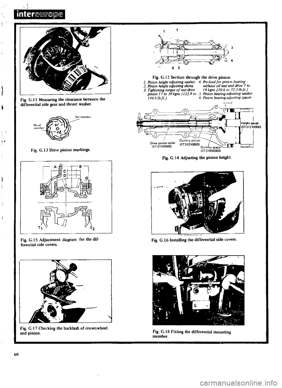
Fig
G
12
Section
through
the
drive
pinion
1
Pinion
height
adjusting
kUsher
4
Fte
Ioad
for
pinion
bearing
2
Pinion
height
ad
usting
shims
without
oil
mlI
and
drive
7
to
3
Tightening
torque
of
nut
dril
e
10
kgt1L
5a
6
to
72
3
lb
jl
pinion
17
to
20kg1n
22
9
to
ffnion
bearing
adjusting
w
uher
44
6Ib
ft
J
6
Pillion
bt
flrillgadjusti
lg
s
Jtu
er
fl
i
Ji
l
I
I
J
lJ
i
V
r
IHei
t
giluge
I
lST31210c
0
l
B
I
0
QJ
DUrnmYPinlOn
Drive
pinion
collar
lST3121QOCX
f
1
L
r
IST315000001
Dummvspacer
ST318500001
I
Fig
G
ll
Measuring
the
clearance
between
the
differential
side
gear
and
thrust
washer
Fig
G
t3
Drive
pinion
markings
Fig
G
14
Adjusting
the
pinion
height
1
Fig
G
t
5
Adjustment
diagram
for
the
dif
feren
tiaI
side
covers
Fig
G
16lnstalling
the
differential
side
covers
fig
G
Checking
the
backlash
of
crownwheel
and
pinion
Fig
G
tS
Fining
the
differential
mounting
member
bb
Page 68 of 171
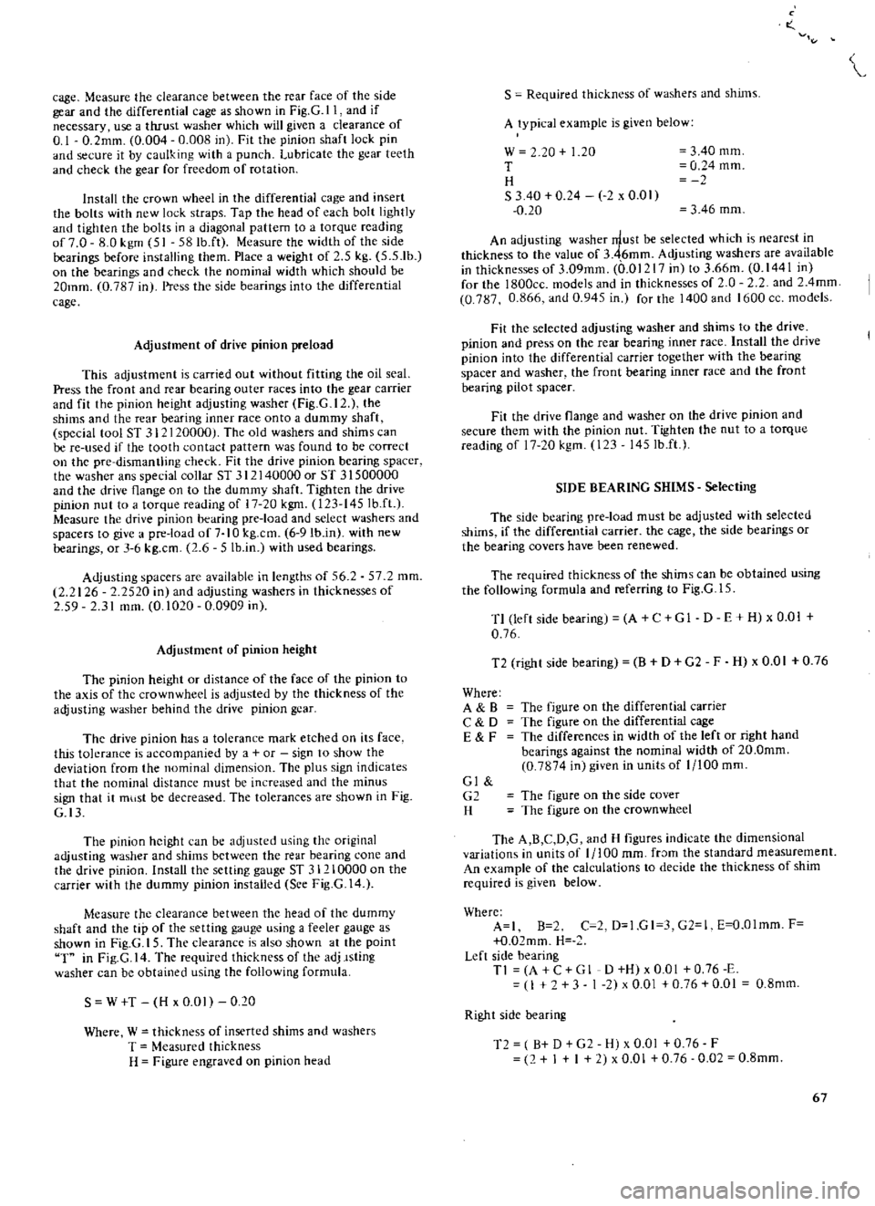
cage
Mcasure
the
clearance
between
the
rear
face
of
thc
side
gear
and
the
differential
cage
as
shown
in
Fig
G
ll
and
if
necessary
use
a
tluust
washer
which
will
given
a
clearance
of
0
1
0
2mm
0
004
0
008
in
Fit
the
pinion
shaft
lock
pin
and
secure
it
by
caulking
with
a
punch
Lubricate
the
gear
teeth
and
check
the
gear
for
freedom
of
rotation
Install
the
crown
wheel
in
the
differential
cage
and
insert
the
bolts
with
new
lock
straps
Tap
the
head
of
each
bolt
lightly
and
tighten
the
bolts
in
a
diagonal
pattern
to
a
torque
reading
of
7
0
8
0
kgm
51
58Ib
ft
Measure
the
width
of
the
side
bearings
before
installing
them
Place
a
weight
of
2
5
kg
5
5
1b
on
the
bearings
and
check
the
nominal
width
which
should
be
20mm
0
787
in
Press
the
side
bearings
into
the
differential
cage
Adjustment
of
drive
pinion
preload
This
adjustment
is
carried
out
without
fitting
the
oil
seal
Press
the
front
and
rear
bearing
outer
races
into
the
gear
carrier
and
fit
the
pinion
height
adjusting
washer
Fig
G
12
the
shims
and
the
rear
bearing
inner
race
onto
a
dummy
shaft
special
tool
ST
31
120000
The
old
washers
and
shims
can
be
re
used
if
the
tooth
contact
pattern
was
found
to
be
correct
on
the
pre
dismantling
check
Fit
the
drive
pinion
bearing
spacer
the
washer
ans
special
collar
5T
312140000
or
5T
31500000
and
the
drive
flange
on
to
the
dummy
shaft
Tighten
the
drive
pinion
nut
to
a
torque
reading
of
17
20
kgm
123
145
Ib
ft
Measure
the
drive
pinion
bearing
pre
load
and
select
washers
and
spacers
to
give
a
pre
load
of
7
1
0
kg
cm
6
9Ib
in
with
new
bearings
or
3
6
kg
cm
2
6
5
Ib
in
with
used
bearings
Adjusting
spacers
are
available
in
lengths
of
56
2
57
2
mm
2
2126
2
2520
in
and
adjusting
washers
in
thicknesses
of
59
2
31
mm
0
1020
0
0909
in
Adjustment
of
pinion
height
The
pinion
height
or
distance
of
the
face
of
the
pinion
to
the
axis
of
the
crownwheel
is
adjusted
by
the
thickness
of
the
adjusting
washer
behind
the
drive
pinion
gcar
The
drive
pinion
has
a
tolerance
mark
etched
on
its
face
this
tokrance
is
accompanied
by
a
or
sign
to
show
the
deviation
from
the
nominal
dimension
Thc
plus
sign
indicates
that
the
nominal
distance
must
be
increased
and
the
minus
sign
that
it
mllst
be
decreased
The
tolerances
are
shown
in
Fig
G
I3
The
pinion
height
can
be
adjusted
using
the
original
adjusting
washer
and
shims
between
the
rear
bearing
cone
and
the
drive
pinion
Install
the
setting
gauge
5T
31210000
on
the
carrier
with
the
dummy
pinion
installed
Sce
Fig
G
14
Measure
the
clearance
between
the
head
of
the
dummy
shaft
and
the
tip
of
the
setting
g
wge
using
a
feeler
gauge
as
shown
in
Fig
G
15
The
clearance
is
also
shown
at
the
point
T
in
Fig
G
14
The
required
thickness
of
the
adj
lsting
washer
can
be
obtained
using
the
following
formula
S
W
T
H
x
0
01
0
20
Where
W
thickness
of
inserted
shims
and
washers
T
Measured
thickness
H
Figure
engraved
on
pinion
head
o
S
Required
thickn
ss
of
washers
and
shims
A
typical
example
is
given
below
w
20
1
20
T
H
S
340
0
24
2
x
0
01
0
20
3
40
mm
0
24
mm
3
46
mm
An
adjusting
washer
rrlust
be
selected
which
is
nearest
in
thickness
to
the
value
of
3
46mm
Adjusting
washers
are
available
in
thicknesses
of
3
09mm
0
01217
in
to
3
66m
0
1441
in
for
the
l800cc
models
and
in
thicknesses
of
O
2
and
2
4mm
0
787
0
866
and
0
945
in
for
the
1400
and
1600
cc
models
Fit
the
selected
adjusting
washer
and
shims
to
the
drive
pinion
and
press
on
the
rear
bearing
inner
race
Install
the
drive
pinion
into
the
differential
carrier
together
with
the
bearing
spacer
and
washer
the
front
bearing
inner
race
and
the
front
bearing
pilot
spacer
Fit
the
drive
flange
and
washer
on
the
drive
pinion
and
secure
them
with
the
pinion
nut
Tighten
the
nut
to
a
torque
reading
of
17
20
kgm
123
145Ib
ft
SIDE
BEARING
SHIMS
Selecting
The
side
bearing
pre
load
must
be
adjusted
with
selected
shims
if
the
differential
carrier
the
cage
the
side
bearings
or
the
bearing
covers
have
been
renewed
The
required
thickness
of
the
shims
can
be
obtained
using
the
following
formula
and
referring
to
Fig
G
l
5
T1
left
side
bearing
A
C
GI
D
E
H
x
0
01
0
76
T2
right
side
bearing
B
D
G2
F
H
x
0
01
0
76
Where
A
B
C
D
E
F
The
figure
on
the
differential
carrier
The
figure
on
the
differential
cage
The
differences
in
width
of
the
left
or
right
hand
bearings
against
the
nominal
width
of
20
0mm
0
7874
in
given
in
units
of
1
100
mm
Gl
G2
H
The
figure
on
the
side
cover
The
figure
on
the
crownwheel
The
A
B
C
D
G
and
H
figures
indicate
the
dimensional
variations
in
units
of
1
100
mm
fr
Jm
the
standard
measurement
An
example
of
the
calculations
to
decide
the
thickness
of
shim
required
is
given
below
Where
A
I
B
2
C
2
D
1
GI
3
G2
1
E
O
Olmm
F
O
02mm
H
Left
side
bearing
Tl
A
C
G
1
D
H
x
0
01
0
76
E
I
3
1
2
x
0
01
0
76
0
01
0
8mm
Right
side
bearing
T2
B
D
G2
H
x
0
01
0
76
F
2
I
I
2
x
0
01
0
76
0
02
0
8mm
67
Page 72 of 171
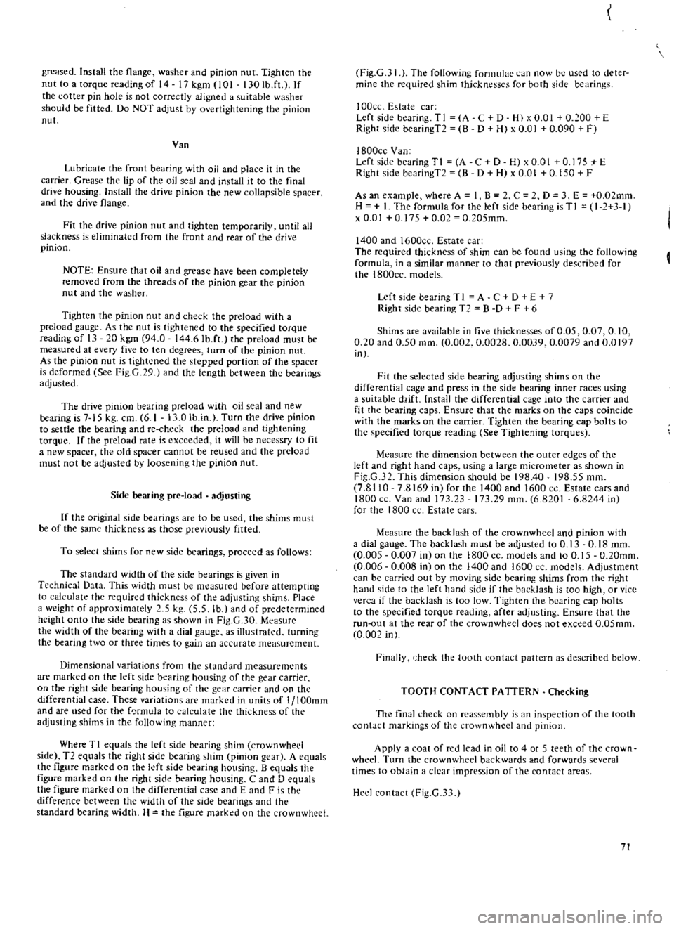
greased
Install
the
flange
washer
and
pinion
nut
Tighten
the
nut
to
a
torque
reading
of
14
17
kgm
101
130
Ib
fL
If
the
cotter
pin
hole
is
not
correctly
aligned
a
suitable
washer
should
be
fitted
Do
NOT
adjust
by
overtightening
the
pinion
nul
Van
Lubricate
the
front
bearing
with
oil
and
place
it
in
the
carrier
Grease
the
lip
of
the
oil
seal
and
install
it
to
the
final
drive
housing
Install
the
drive
pinion
the
new
collapsible
spacer
and
the
drive
flange
Fit
the
drive
pinion
nut
and
tighten
temporarily
until
all
slackness
is
eliminated
from
the
front
and
rear
of
the
drive
pinion
NOTE
Ensure
that
oil
and
grease
have
been
completely
removed
from
the
threads
of
the
pinion
gear
the
pinion
nut
and
the
washer
Tighten
the
pinion
nut
and
check
the
preload
with
a
preload
gauge
As
the
nut
is
tightened
to
the
specified
torque
reading
of
13
20
kgm
94
0
144
6Ib
fL
the
preload
must
be
measured
at
every
five
to
ten
degrees
turn
of
the
pinion
nut
As
the
pinion
nut
is
tightened
the
stepped
portion
of
the
spacer
is
deformed
See
Fig
G
29
J
and
the
length
between
the
bearings
adjusted
The
drive
pinion
bearing
preload
with
oil
seal
and
new
bearing
is
7
15
kg
cm
6
1
13
0
lb
in
Turn
the
drive
pinion
to
settle
the
bearing
and
re
check
the
preload
and
tightening
torque
If
the
preload
rate
is
exceeded
it
will
be
necessry
to
fit
a
new
spacer
the
old
spa
cr
cannot
be
reused
and
the
preload
must
not
be
adjusted
by
loosening
the
pinion
nul
Side
bearing
pre
load
adjusting
If
the
original
side
bearings
arc
to
be
used
the
shims
must
be
of
the
same
thickness
as
those
previously
fitted
To
select
shims
for
new
side
bearings
proceed
as
follows
The
standard
width
of
the
side
bearings
is
given
in
Technical
Data
This
width
must
be
measured
before
attempting
to
calculate
the
required
thickness
of
the
adjusting
shims
Place
a
weight
of
approximately
5
kg
5
5
lb
and
of
predetermined
height
onto
the
side
bearing
as
shown
in
Fig
G
30
Mcasure
the
width
of
the
bearing
with
a
dial
gauge
as
illustrated
turning
the
bearing
two
or
three
times
to
gain
an
accurate
meaSurement
Dimensional
variations
from
the
standard
measurements
are
marked
on
the
left
side
bearing
housing
of
the
gear
carrier
on
the
right
side
bearing
housing
of
the
gear
carrier
and
on
the
differential
case
These
variations
are
marked
in
units
of
l
lOOmm
and
are
used
for
the
f
rmula
to
calculate
t1H
thickness
of
the
adjusting
shims
in
the
following
manner
Where
TI
equals
the
left
side
bearing
shim
crownwhecl
side
T2
equals
the
right
side
bearing
shim
pinion
gear
A
equals
the
figure
marked
on
the
left
side
bearing
housing
B
equals
the
figure
marked
on
the
right
side
bearing
housing
C
and
0
equals
the
figure
marked
on
the
differential
case
and
E
and
F
is
the
difference
bctween
the
width
of
the
side
bearings
and
the
standard
bearing
width
H
the
figure
marked
on
the
crownwhcel
Fig
G
31
The
following
formulae
can
now
be
used
to
deter
mine
the
required
shim
thicknessl
s
for
both
side
bearings
I
OOcc
Estate
car
Left
side
bearing
TI
A
C
D
H
x
0
01
0
100
E
Right
side
bearingT2
B
D
H
x
0
01
0
090
F
I800cc
Van
Left
side
bearingTI
A
C
D
H
xO
OI
0
175
E
Right
side
bcaringT2
8
D
H
x
0
01
0
150
F
As
an
example
where
A
1
B
C
2
D
3
E
0
02mm
H
I
The
formula
for
the
left
side
bearing
is
T
I
I
1
3
1
x
0
01
0
175
0
02
0
205mm
1400
and
1600cc
Estate
car
The
required
thickness
of
shim
can
be
found
using
the
following
formula
in
a
similar
manner
to
that
previously
described
for
the
1800cc
models
Left
side
bearing
T
I
A
C
D
E
7
Right
side
bearing
T2
B
D
F
6
Shims
are
available
in
five
thicknesses
of
0
05
0
07
0
10
0
20
and
0
50
mm
0
002
0
0028
0
0039
0
0079
and
0
0197
in
Fit
the
selected
side
bearing
adjusting
shims
on
the
differential
cage
and
press
in
the
side
bearing
inner
races
using
a
suitable
ddfL
nstall
the
differential
cage
into
the
carrier
and
fit
the
bearing
caps
Ensure
that
the
marks
on
the
caps
coincide
with
the
marks
on
the
carrier
Tighten
the
bearing
cap
bolts
to
the
specified
torque
reading
See
Tighte
ing
torques
Measure
the
dimension
between
the
outer
edges
of
the
left
and
right
hand
caps
using
a
large
micrometer
as
shown
in
Fig
G
32
This
dimension
should
be
198
40
198
55
mm
7
8110
7
8169
in
for
the
1400
and
1600
ce
Estate
cars
and
1800
ce
Van
and
173
23
17329
mm
6
8201
6
8244
inl
for
the
1800
cc
Estate
cars
Measure
the
backlash
of
the
crownwhcel
and
pinion
with
a
dial
gauge
The
backlash
must
be
adjusted
to
0
13
0
18
mm
0
005
0
007
in
on
the
1800
CC
models
and
to
0
15
0
20mm
0
006
0
008
in
on
the
1400
and
1600
cc
models
Adjustment
can
be
carried
out
by
moving
side
bearing
shims
from
the
right
hand
side
to
the
left
hand
side
if
the
backlash
is
too
high
or
vice
verca
if
the
backlash
is
too
low
Tighten
the
bearing
cap
bolts
to
the
specified
torque
reading
after
adjusting
Ensure
that
the
run
out
at
the
rear
of
the
crown
wheel
does
not
exceed
O
05mm
0
002
in
Finally
heck
the
tooth
contact
pattern
as
described
below
TOOTH
CONTACT
PATTERN
Checking
The
final
check
on
reassembly
is
an
inspection
of
the
tooth
contact
markings
of
the
crownwhed
and
pinion
Apply
a
coal
of
red
lead
in
oil
to
4
or
5
teeth
of
the
crown
wheel
Turn
the
crownwheel
backwards
and
forwards
several
times
to
obtain
a
clear
impression
of
the
contact
areas
Heel
contact
Fig
G
3
1
71
Page 100 of 171
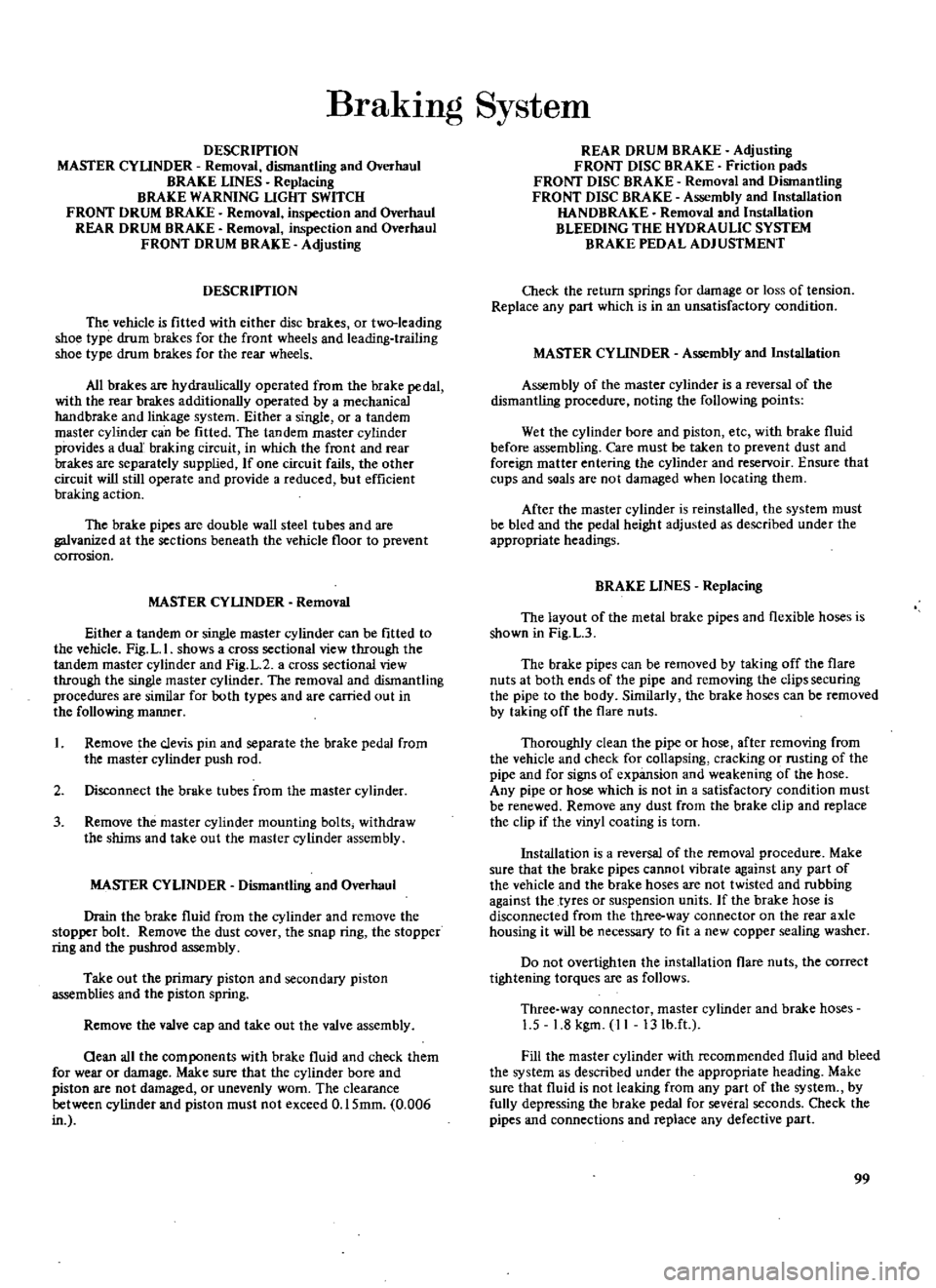
BrakIng
System
DESCRIPTION
MASTER
CYLINDER
Removal
dismantling
and
Overhaul
BRAKE
LINES
Replacing
BRAKE
WARNING
LIGHT
SWITCH
FRONT
DRUM
BRAKE
Removal
inspection
and
Overhaul
REAR
DRUM
BRAKE
Removal
inspection
and
Overhaul
FRONT
DRUM
BRAKE
Adjusting
DESCRIPTION
The
vehicle
is
fitted
with
either
disc
brakes
or
two
leading
shoe
type
drum
brakes
for
the
front
wheels
and
leading
trailing
shoe
type
drum
brakes
for
the
rear
wheels
All
brakes
are
hydraulically
operated
from
the
brake
pedal
with
the
rear
brakes
additionally
operated
by
a
mechanical
handbrake
and
linkage
system
Either
a
single
or
a
tandem
master
cylinder
can
be
fitted
The
tandem
master
cylinder
provides
a
dual
braking
circuit
in
which
the
front
and
rear
brakes
are
separately
supplied
If
ODe
circuit
fails
the
other
circuit
will
still
operate
and
provide
a
reduced
but
efficient
braking
action
The
brake
pipes
are
double
wall
steel
tubes
and
are
galvanized
at
the
sections
beneath
the
vehicle
floor
to
prevent
corrosion
MASTER
CYLINDER
Removal
Either
a
tandem
or
single
master
cylinder
can
be
fitted
to
the
vehicle
Fig
L
I
shows
a
cross
sectional
view
through
the
tandem
master
cylinder
and
Fig
L
2
a
cross
sectional
view
through
the
single
master
cylinder
The
removal
and
dismantling
procedures
are
similar
for
both
types
and
are
carried
out
in
the
following
manner
1
Remove
the
clevis
pin
and
separate
the
brake
pedal
from
the
master
cylinder
push
rod
2
Disconnect
the
brake
tubes
from
the
master
cylinder
3
Remove
the
master
cylinder
mounting
bolts
withdraw
the
shims
and
take
out
the
master
cylinder
assembly
MASfER
CYLINDER
Dismantling
and
Overhaul
Drain
the
brake
fluid
from
the
cylinder
and
remove
the
stopper
bolt
Remove
the
dust
cover
the
snap
ring
the
stopper
ring
and
the
pusbrod
assembly
Take
out
the
primary
piston
and
secondary
piston
assemblies
and
the
piston
spring
Remove
the
valve
cap
and
take
out
the
valve
assembly
Oean
all
the
components
with
brake
fluid
and
check
them
for
wear
or
damage
Make
sure
that
the
cylinder
bore
and
piston
are
not
damaged
or
unevenly
worn
The
clearance
between
cylinder
and
piston
must
not
exceed
0
15mm
0
006
in
REAR
DRUM
BRAKE
Adjusting
FRONT
DISC
BRAKE
Friction
pads
FRONT
DISC
BRAKE
Removal
and
Dismantling
FRONT
DISC
BRAKE
Assembly
and
Installation
HANDBRAKE
Removal
and
Installation
BLEEDING
THE
HYDRAULIC
SYSTEM
BRAKE
PEDAL
ADJUSTMENT
Check
the
return
springs
for
damage
or
loss
of
tension
Replace
any
part
which
is
in
an
unsatisfactory
condition
MASfER
CYLINDER
Assembly
and
Installation
Assembly
of
the
master
cylinder
is
a
reversal
of
the
dismantling
procedure
noting
the
following
points
Wet
the
cylinder
bore
and
piston
etc
with
brake
fluid
before
assembling
Care
must
be
taken
to
prevent
dust
and
foreign
matter
entering
the
cylinder
and
reservoir
Ensure
that
cups
and
soals
are
not
damaged
when
locating
them
After
the
master
cylinder
is
reinstalled
the
system
must
be
bled
and
the
pedal
height
adjusted
as
described
under
the
appropriate
headings
BRAKE
LINES
Replacing
The
layout
of
the
metal
brake
pipes
and
flexible
hoses
is
shown
in
Fig
L
3
The
brake
pipes
can
be
removed
by
taking
off
the
flare
nuts
at
both
ends
of
the
pipe
and
removing
the
clips
securing
the
pipe
to
the
body
Similarly
the
brake
hoses
can
be
removed
by
taking
off
the
flare
nuts
Thoroughly
clean
the
pipe
or
hose
after
removing
from
the
vehicle
and
check
for
collapsing
cracking
or
rusting
of
the
pipe
and
for
signs
of
expansion
and
weakening
of
the
hose
Any
pipe
or
hose
which
is
not
in
a
satisfactory
condition
must
be
renewed
Remove
any
dust
from
the
brake
clip
and
replace
the
clip
if
the
vinyl
coating
is
torn
Installation
is
a
reversal
of
the
removal
procedure
Make
sure
that
the
brake
pipes
cannot
vibrate
against
any
part
of
the
vehicle
and
the
brake
hoses
are
not
twisted
and
rubbing
against
the
tyres
or
suspension
units
If
the
brake
hose
is
disconnected
from
the
three
way
connector
on
the
rear
axle
housing
it
will
be
necessary
to
fit
a
new
copper
sealing
washer
Do
not
overtighten
the
installation
flare
nuts
the
correct
tightening
torques
are
as
follows
Three
way
connector
master
cylinder
and
brake
hoses
1
5
1
8
kgm
II
13Ib
ft
Fill
the
master
cylinder
with
recommended
fluid
and
bleed
the
system
as
described
under
the
appropriate
heading
Make
sure
that
fluid
is
not
leaking
from
any
part
of
the
system
by
fully
depressing
the
brake
pedal
for
several
seconds
Check
the
pipes
and
connections
and
replace
any
defective
part
99
Page 108 of 171
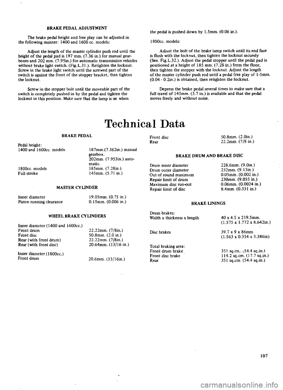
BRAKE
PEDAL
ADJUSTMENT
The
brake
pedal
height
and
free
play
can
be
adjusted
in
the
following
manner
1400
and
1600
CC
models
Adjust
the
length
of
the
master
cylinder
push
rod
until
the
height
of
the
pedal
pad
is
187
mm
7
36
in
for
manual
gear
boxes
and
202
mm
7
95in
for
automatic
transmission
vehicles
without
brake
light
switch
Fig
L
31
Retighten
the
locknut
Screw
in
the
brake
light
switch
until
the
screwed
part
of
the
switch
is
against
the
front
of
the
stopper
bracket
then
tighten
the
locknut
Screw
in
the
stopper
bolt
until
the
moveable
part
of
the
switch
is
completely
pushed
in
by
the
pedal
and
tighten
the
locknut
in
this
position
Make
sure
that
the
lamp
is
00
when
the
pedal
is
pushed
down
by
1
5mm
0
06
in
1800cc
models
Adjust
the
bolt
of
the
brake
lamp
switch
until
its
end
face
is
flush
with
the
locknut
then
tighten
the
locknut
securely
See
Fig
L
32
Adjust
the
pedal
stopper
until
the
pedal
pad
is
positioned
at
a
height
of
185
mrn
7
28
in
from
the
floor
then
tighten
the
stopper
with
the
locknut
Adjust
the
length
of
the
master
cylinder
push
rod
until
a
pedal
free
play
of
I
5mm
0
04
D
2in
is
obtained
then
retighten
the
locknut
Depress
the
brake
pedal
several
times
to
make
sure
that
a
full
travel
of
145mm
5
7
in
is
available
and
that
the
pedal
moves
freely
and
without
noise
Technical
Data
BRAKE
PEDAL
Pedal
height
1400
and
1600cc
models
I
87mm
7
362in
manual
gearbox
202mm
7
953in
auto
matic
185mm
7
28in
145mm
5
71
in
1800cc
models
Full
stroke
MASTER
CYUNDER
Inner
diameter
Piston
running
clearance
19
05mm
0
75
in
0
15mm
0
006
in
WHEEL
BRAKE
CYLINDERS
Inner
diameter
1400
and
1600cc
Front
drum
Front
disc
Rear
with
front
drum
Rear
with
front
disc
22
22mm
7
8in
50
8mm
2
0
in
22
22mm
7
8in
20
64mm
13
16
in
Inner
diameter
I
BOOcc
Front
drum
20
6mm
13
16in
Front
disc
Rear
50
8mm
2
0in
22
2mm
7
8
in
BRAKE
DRUM
AND
BRAKE
DISC
Drum
inner
diameter
Drum
outer
diameter
Out
of
round
maximum
Repair
limit
of
drum
Maximum
disc
run
out
Repair
limit
of
disc
228
6mm
9
0in
232mm
9
13in
0
05mm
0
002
in
230mm
9
055
in
0
06mm
0
0024
in
8
4mm
0
331
in
BRAKE
UNINGS
Drum
brakes
Width
x
thickness
x
length
40
x
4
5
x
219
5mm
1
575
x
1
772
x
8
642in
Disc
brakes
39
7
x
9
x
86mm
1
563
x
0
354
x
3
386in
Total
braking
area
Front
drum
brake
Front
disc
brake
Rear
351
sq
cn
54
4
sq
in
114
2
sq
cm
17
7
sq
in
351
sq
cm
54
4
sq
in
107