technical specifications DATSUN 610 1969 Workshop Manual
[x] Cancel search | Manufacturer: DATSUN, Model Year: 1969, Model line: 610, Model: DATSUN 610 1969Pages: 171, PDF Size: 10.63 MB
Page 23 of 171
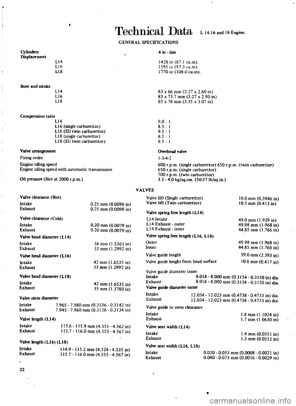
TechnIcal
Data
L
14
16
and
18
Engine
GENERAL
SPECIFICATIONS
Cylinders
Displacement
L14
L16
L18
Bore
and
stroke
L14
L16
Ll8
Compression
ratio
L14
L16
single
carburettor
L16
SU
twin
carburettor
L18
single
carburettor
Ll8
SU
twin
carburettor
Valve
arrangement
Firing
order
e
idling
speed
Engine
idling
speed
with
automatic
transmission
Oil
pressure
Hot
at
2000
r
p
m
Valve
clearance
Hot
Intake
Exhaust
0
25
mm
0
0098
in
0
25
mm
0
0098
in
Valve
clearance
Cold
Intake
Exhaust
Va
head
diameter
L14
Intake
Exhaust
Vahoe
head
diameter
L16
Intake
Exhaust
0
20
mm
0
0079
in
0
20
mm
0
0079
in
38
mm
1
5361
in
33
mm
1
2992
in
42
mm
1
6535
in
33
rom
1
2992
in
Valve
head
diameter
L18
Intake
Exhaust
42
mm
1
6535
in
35
mm
1
3780
in
Valve
stem
diameter
Intake
7
965
7
980
mm
0
3136
0
3142
in
Exhaust
7
945
7
960
mm
0
3128
0
3134
in
Valve
length
L14
Intake
Exhaust
115
6
115
9mm
4
551
4
562in
115
7
116
0
mm
4
555
4
567
in
Valve
length
L16
LIB
Intake
114
9
115
2
mm
4
524
4
535
in
Exhaust
115
7
116
0
mm
4
555
4
567
in
22
4
in
line
1428
cc
87
1
cu
in
1595
cc
97
3
cu
in
1770
cc
108
0
cu
in
83
x
66
mm
3
27
x
2
60
in
83
x
73
7
mm
3
27
x
2
90
in
85
x
7B
mm
3
35
x
3
07
in
9
0
8
5
9
5
8
5
9
5
Overhead
valve
I
3
4
600
r
p
m
single
carburettor
650
r
p
m
twin
carburettor
650
r
p
m
single
carburettor
700
r
p
m
twin
carburettor
3
5
4
0
kg
sq
cm
50
57Ib
sq
in
VALVES
Valve
lift
Single
carburettor
Valve
lift
Twin
carburettor
10
0
mm
0
3946
in
10
5
mm
0
413
in
Valve
spring
free
length
LI4
Ll4
Intake
Ll4
Exhaust
outer
L14
Exhaust
inner
Valve
sprin8
free
length
L16
LIB
Outer
Inner
49
0
mm
1
929
in
49
98
mm
1
968
in
44
85
mm
1
766
in
49
98
mm
1
968
in
44
85
mm
1
766
in
59
0
mm
2
393
in
10
6
mm
0
417
in
Valve
guide
length
Valve
guide
height
from
head
surface
Valve
guide
diameter
inner
Intake
8
018
Exhaust
8
018
Valve
guide
diameter
outer
Intake
12
034
Exhaust
12
034
Valve
guide
to
stem
clearance
Intake
Exhaust
Valve
seat
width
L14
Intake
Exhaust
Valve
seat
width
L16
LIB
Intake
Exhaust
8
000
mm
0
3154
0
3150
in
clia
8
000
mm
0
3154
0
3150
in
clia
12
023
mm
0
4738
0
4733
in
clia
12
023
mm
0
4738
0
4733
in
clia
1
8
mm
1
1024
in
I
7
mm
1
0630
in
I
4
mm
0
0551
in
1
3
mm
0
0512
in
0
020
0
053
mm
0
0008
0
0021
in
0
040
0
073
mm
0
0016
0
0029
in
Page 46 of 171
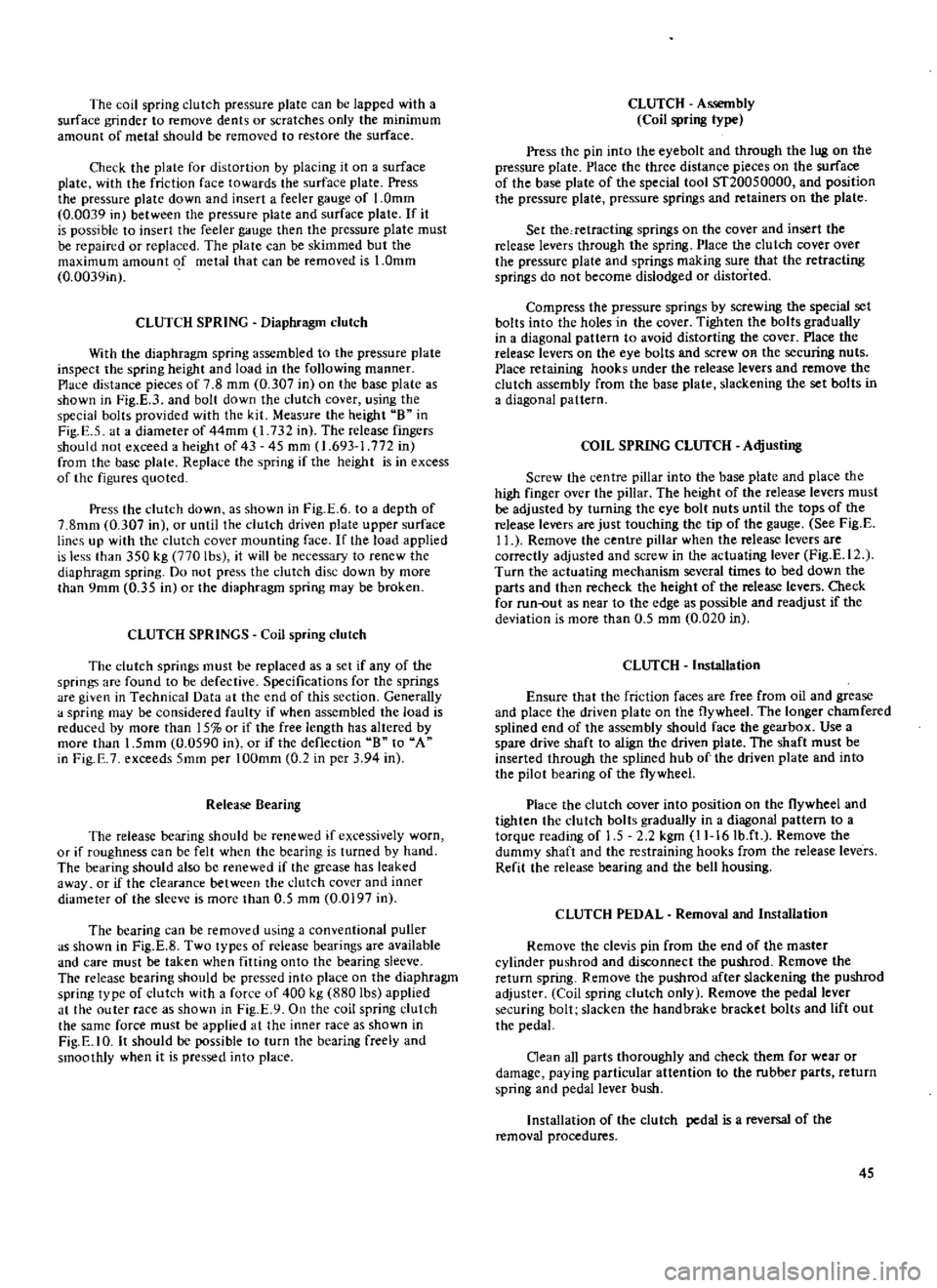
The
coil
spring
clutch
pressure
plate
can
be
lapped
with
a
surface
grinder
to
remove
dents
or
scratches
only
the
minimum
amount
of
metal
should
be
removed
to
restore
the
surface
Check
the
plate
for
distortion
by
placing
it
on
a
surface
plate
with
the
friction
face
towards
the
surface
plate
Press
the
pressure
plate
down
and
insert
a
feeler
gauge
of
1
0mm
0
0039
in
between
the
pressure
plate
and
surface
plate
If
it
is
possible
to
insert
the
feeler
gauge
then
the
pressure
plate
must
be
repaired
or
replaced
The
plate
can
be
skimmed
but
the
maximum
amount
of
metal
that
can
be
removed
is
1
0mm
0
0039in
CLUTCH
SPRING
Diaphragm
clutch
With
the
diaphragm
spring
assembled
to
the
pressure
plate
inspect
the
spring
height
and
load
in
the
following
manner
Place
distance
pieces
of
7
8
mm
0
307
in
on
the
base
plate
as
shown
in
Fig
E
3
and
bolt
down
the
clutch
cover
using
the
special
bolts
provided
with
the
kit
Meas
Jre
the
height
B
in
Fig
E
5
at
a
diameter
of
44mm
1
732
in
The
release
fingers
should
not
exceed
a
height
of
43
45
mm
1
693
1
772
in
from
the
base
plate
Replace
the
spring
if
the
height
is
in
excess
of
the
figures
quoted
Press
the
dutch
down
as
shown
in
Fig
E
6
to
a
depth
of
7
8mm
0
307
in
or
until
the
clutch
driven
plate
upper
surface
lines
up
with
the
clutch
cover
mounting
face
If
the
load
applied
is
less
than
350
kg
770
lbs
it
will
be
necessary
to
renew
the
diaphragm
spring
Do
not
press
the
clutch
disc
down
by
more
than
9mm
0
35
in
or
the
diaphragm
spring
may
be
broken
CLUTCH
SPRINGS
Coil
spring
clutch
The
clutch
springs
must
be
replaced
as
a
set
if
any
of
the
springs
are
found
to
be
defective
Specifications
for
the
springs
are
given
in
Technical
Data
at
the
end
of
this
section
Generally
a
spring
may
be
considered
faulty
if
when
assembled
the
load
is
reduced
by
more
than
15
or
if
the
free
length
has
altered
by
more
than
1
5mm
0
0590
in
or
if
the
deflection
B
to
A
in
Fig
E
7
exceeds
5mm
per
100mm
0
2
in
per
3
94
in
Release
Bearing
The
release
bearing
should
be
renewed
if
excessively
worn
or
if
roughness
can
be
felt
when
the
bearing
is
turned
by
hand
The
bearing
should
also
be
renewed
if
the
grease
has
leaked
away
or
if
the
clearance
between
the
clutch
cover
and
inner
diameter
of
the
sleeve
is
more
than
0
5
mm
0
0197
in
The
bearing
can
be
removed
using
a
conventional
puller
as
shown
in
Fig
E
8
Two
types
of
release
bearings
are
available
and
care
must
be
taken
when
fitting
onto
the
bearing
sleeve
The
release
bearing
should
be
pressed
into
place
on
the
diaphragm
spring
type
of
clutch
with
a
force
of
400
kg
880
lbs
applied
at
the
outer
race
as
shown
in
Fig
E
9
On
the
coil
spring
clutch
the
same
force
must
be
applied
at
the
inner
race
as
shown
in
Fig
E
IO
It
should
be
possible
to
turn
the
bearing
freely
and
smoothly
when
it
is
pressed
into
place
CLUTCH
Assembly
Coil
spring
type
Press
the
pin
into
the
eyebolt
and
through
the
lug
on
the
pressure
plate
Place
the
three
distance
pieces
on
the
surface
of
the
base
plate
of
the
special
tool
ST20050000
and
position
the
pressure
plate
pressure
springs
and
retainers
on
the
plate
Set
the
retracting
springs
on
the
cover
and
insert
the
release
levers
through
the
spring
Place
the
clutch
cover
over
the
pressure
plate
and
springs
making
sure
that
the
retracting
springs
do
not
become
dislodged
or
distorted
Compress
the
pressure
springs
by
screwing
the
special
set
bolts
into
the
holes
in
the
cover
Tighten
the
bolts
gradually
in
a
diagonal
pattern
to
avoid
distorting
the
cover
Place
the
release
levers
on
the
eye
bolts
and
screw
OR
the
securing
nuts
Place
retaining
hooks
under
the
release
levers
and
remove
the
clutch
assembly
from
the
base
plate
slackening
the
set
bolts
in
a
diagonal
pattern
COIL
SPRING
CLUTCH
Adjusting
Screw
the
centre
pillar
into
the
base
plate
and
place
the
high
finger
over
the
pillar
The
height
of
the
release
levers
must
be
adjusted
by
turning
the
eye
bolt
nuts
until
the
tops
of
the
release
levers
are
just
touching
the
tip
of
the
gauge
See
Fig
E
11
Remove
the
centre
pillar
when
the
release
levers
are
correctly
adjusted
and
screw
in
the
actuating
lever
Fig
E
12
Turn
the
actuating
mechanism
several
times
to
bed
down
the
parts
and
then
recheck
the
height
of
the
release
levers
Check
for
run
out
as
near
to
the
edge
as
possible
and
readjust
if
the
deviation
is
more
than
0
5
mrn
0
020
in
CLUTCH
InsWlation
Ensure
that
the
friction
faces
are
free
from
oil
and
grease
and
place
the
driven
plate
on
the
flywheel
The
longer
chamfered
splined
end
of
the
assembly
should
face
the
gearbox
Use
a
spare
drive
shaft
to
align
the
driven
plate
The
shaft
must
be
inserted
through
the
splined
hub
of
the
driven
plate
and
into
the
pilot
bearing
of
the
flywheel
Place
the
clutch
cover
into
position
on
the
flywheel
and
tighten
the
dutch
bolts
gradually
in
a
diagonal
pattern
to
a
torque
reading
of
1
5
2
2
kgm
11
16Ib
ft
Remove
the
dummy
shaft
and
the
restraining
hooks
from
the
release
levers
Refit
the
release
bearing
and
the
bell
housing
CLUTCH
PEDAL
Removal
and
Installation
Remove
the
clevis
pin
from
the
end
of
the
master
cylinder
pushrod
and
disconnect
the
pushrod
Remove
the
return
spring
Remove
the
pushrod
after
slackening
the
pushrod
adjuster
Coil
spring
clutch
only
Remove
the
pedal
lever
securing
bolt
slacken
the
handbrake
bracket
bolts
and
lift
out
the
pedal
Clean
all
parts
thoroughly
and
check
them
for
wear
or
damage
paying
particular
attention
to
the
rubber
parts
return
spring
and
pedal
lever
bush
Installation
of
the
clutch
pedal
is
a
reversal
of
the
removal
procedures
45
Page 58 of 171
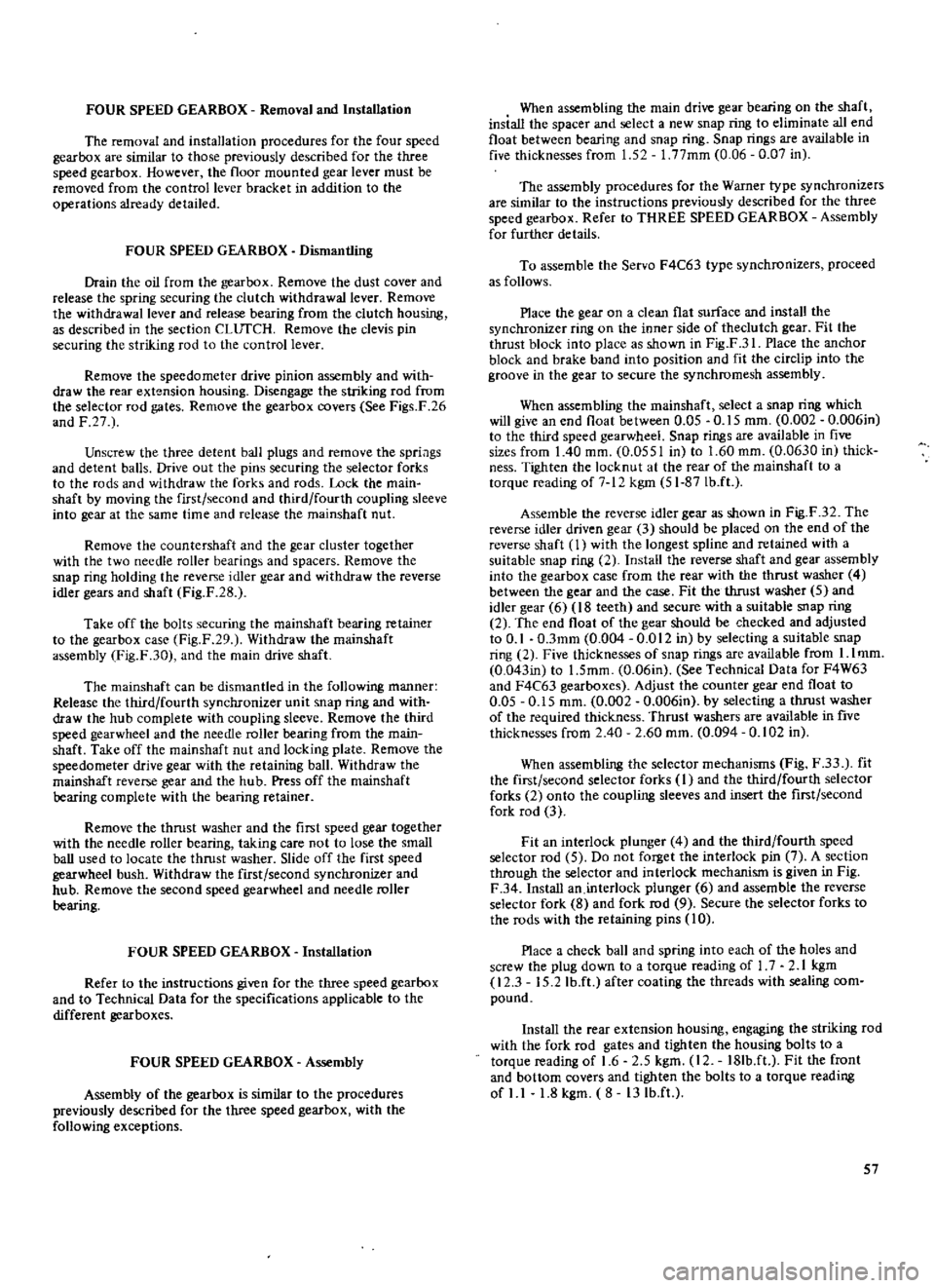
FOUR
SPEED
GEARBOX
Removal
and
Installation
The
removal
and
installation
procedures
for
the
four
speed
gearbox
are
similar
to
those
previously
described
for
the
three
speed
gearbox
However
the
floor
mounted
gear
lever
must
be
removed
from
the
controllevef
bracket
in
addition
to
the
operations
already
detailed
FOUR
SPEED
GEARBOX
Dismantling
Drain
the
oil
from
the
gearbox
Remove
the
dust
coveT
and
release
the
spring
securing
the
clutch
withdrawal
lever
Remove
the
withdrawal
lever
and
release
bearing
from
the
clutch
housing
as
described
in
the
section
CLurCH
Remove
the
clevis
pin
securing
the
striking
rod
to
the
control
lever
Remove
the
speedometer
drive
pinion
assembly
and
with
draw
the
rear
extension
housing
Disengage
the
striking
rod
from
the
selector
rod
gates
Remove
the
gearbox
covers
See
Figs
F
26
and
F
27
Unscrew
the
three
detent
ball
plugs
and
remove
the
spriags
and
detent
balls
Drive
out
the
pins
securing
the
selector
forks
to
the
rods
and
withdraw
the
forks
and
rods
Lock
the
main
shaft
by
moving
the
first
second
and
third
fourth
coupling
sleeve
into
gear
at
the
same
time
and
release
the
ffiainshaft
nut
Remove
the
countershaft
and
the
gear
cluster
together
with
the
two
needle
roller
bearings
and
spacers
Remove
the
snap
ring
holding
the
revep
e
idler
gear
and
withdraw
the
reverse
idler
gears
and
shaft
Fig
F
28
Take
off
the
bolts
securing
the
mainshaft
bearing
retainer
to
the
gearbox
case
Fig
F
29
Withdraw
the
mainshaft
assembly
Fig
F
30
and
the
main
drive
shaft
The
mainshaft
can
be
dismantled
in
the
following
manner
Release
the
third
fourth
synchronizer
unit
snap
ring
and
with
draw
the
hub
complete
with
coupling
sleeve
Remove
the
third
speed
gearwheel
and
the
needle
roller
bearing
from
the
main
shaft
Take
off
the
mainshaft
nut
and
locking
plate
Remove
the
speedometer
drive
gear
with
the
retaining
ball
Withdraw
the
mainshaft
reverse
gear
and
the
hub
Press
off
the
mainshaft
bearing
complete
with
the
bearing
retainer
Remove
the
thrust
washer
and
the
first
speed
gear
together
with
the
needle
roller
bearing
taking
care
not
to
lose
the
small
baU
used
to
locate
the
thrust
washer
Slide
off
the
first
speed
gearwheel
bush
Withdraw
the
first
second
synchronizer
and
hub
Remove
the
second
speed
gearwheel
and
needle
roller
bearing
FOUR
SPEED
GEARBOX
Installation
Refer
to
the
instructions
given
for
the
three
speed
gearbox
and
to
Technical
Data
for
the
specifications
applicable
to
the
different
gearboxes
FOUR
SPEED
GEARBOX
Assembly
Assembly
of
the
gearbox
is
similar
to
the
procedures
previously
described
for
the
three
speed
gearbox
with
the
following
exceptions
When
assembling
the
main
drive
gear
bearing
on
the
shaft
insiall
the
spacer
and
select
a
new
snap
ring
to
eliminate
all
end
float
between
bearing
and
snap
ring
Snap
rings
are
available
in
five
thicknesses
from
1
52
1
77mm
0
06
0
07
in
The
assembly
procedures
for
the
Warner
type
synchronizers
are
similar
to
the
instructions
previously
described
for
the
three
speed
gearbox
Refer
to
THREE
SPEED
GEARBOX
Assembly
for
further
details
To
assemble
the
Servo
F4C63
type
synchronizers
proceed
as
follows
Place
the
gear
on
a
clean
flat
surface
and
install
the
synchronizer
ring
on
the
inner
side
of
theclutch
gear
Fit
the
thrust
block
into
place
as
shown
in
Fig
F
31
Place
the
anchor
block
and
brake
band
into
position
and
fit
the
circlip
into
the
groove
in
the
gear
to
secure
the
synchromesh
assembly
When
assembling
the
mainshaft
select
a
snap
ring
which
will
give
an
end
float
between
0
05
0
15
mm
0
002
0
006in
to
the
third
speed
gearwheel
Snap
rings
are
available
in
five
sizes
from
1
40
mm
0
0551
in
to
1
60
mm
0
0630
in
thick
ness
Tighten
the
locknut
at
the
rear
of
the
mainshaft
to
a
torque
reading
of
7
1
kgm
51
87Ib
ft
Assemble
the
reverse
idler
gear
as
shown
in
Fig
F
32
The
reverse
idler
driven
gear
3
should
be
placed
on
the
end
of
the
reverse
shaft
1
with
the
longest
spline
and
retained
with
a
suitable
snap
ring
2
Install
the
reverse
shaft
and
gear
assembly
into
the
gearbox
case
from
the
rear
with
the
thrust
washer
4
between
the
gear
and
the
case
Fit
the
thrust
washer
5
and
idler
gear
6
18
teeth
and
secure
with
a
suitable
snap
ring
2
The
end
float
of
the
gear
should
be
checked
and
adjusted
to
0
1
O
3mm
0
004
0
012
in
by
selecting
a
suitable
snap
ring
2
Five
thicknesses
of
snap
rings
are
available
from
I
lmm
0
043in
to
1
5mm
0
06in
See
Technical
Data
for
F4W63
and
F4C63
gearboxes
Adjust
the
counter
gear
end
float
to
0
05
0
15
mm
0
002
0
006in
by
selecting
a
thrust
washer
of
the
required
thickness
Thrust
washers
are
available
in
five
thicknesses
from
2
40
2
60
mm
0
094
0
102
in
When
assembling
the
selector
mechanisms
Fig
F
33
fit
the
first
second
selector
forks
I
and
the
third
fourth
selector
forks
2
onto
the
coupling
sleeves
and
insert
the
first
second
fork
rod
3
Fit
an
interlock
plunger
4
and
the
third
fourth
speed
selector
rod
5
Do
not
forget
the
interlock
pin
7
A
section
through
the
selector
and
interlock
mechanism
is
given
in
Fig
F
34
Install
an
interlock
plunger
6
and
assemble
the
reverse
selector
fork
8
and
fork
rod
9
Secure
the
selector
forks
to
the
rods
with
the
retaining
pins
10
Place
a
check
ball
and
spring
into
each
of
the
holes
and
screw
the
plug
down
to
a
torque
reading
of
1
7
2
1
Jegm
12
3
15
2
Ib
ft
after
coating
the
threads
with
sealing
com
pound
Install
the
rear
extension
housing
engaging
the
striking
rod
with
the
fork
rod
gates
and
tighten
the
housing
bolts
to
a
torque
reading
of
1
6
2
5
kgm
12
18Ib
ft
Fit
the
front
and
bottom
covers
and
tighten
the
bolts
to
a
torque
reading
of
1
1
1
8
kgm
8
13Ib
ft
57
Page 62 of 171
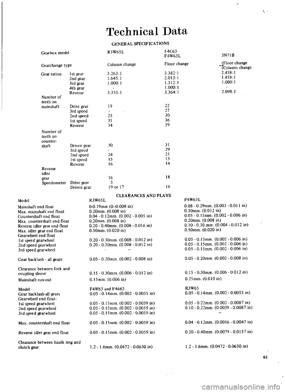
Gearbox
mode
Gearchange
type
Gear
ratios
I
st
gear
2nd
gear
3rd
gear
4th
gear
Reverse
Num
ber
of
teeth
on
mainshaft
Drive
gear
3rd
speed
2nd
speed
1st
speed
Reverse
Num
ber
of
teeth
on
counter
shaft
Driven
gear
3rd
speed
2nd
speed
1st
speed
Reverse
Reverse
idler
gear
Speedometer
Drive
gear
Driven
gear
Technical
Data
GENERAL
SPECIFICATIONS
R3W65
L
F4C63
F4W63L
Column
change
Floor
change
3
263
1
3382
1
1
645
I
2
013
1
1
000
1
1
312
1
1
000
1
3
355
I
3
364
1
19
22
27
25
30
31
36
34
39
3N71B
iFloor
change
Column
change
2
458
1
1458
1
1
000
1
2
098
1
30
31
29
24
21
15
15
16
14
16
18
5
19
or
17
16
CLEARANCES
AND
PLAYS
Model
R3W65L
F4W63L
Mainshaft
end
float
0
0
19mm
0
0
008
in
0
08
0
29mm
0
003
0
0
II
in
Max
mainshaft
end
float
0
20mm
0
008
in
0
30mm
0
012
in
Countershaft
end
float
0
04
0
12mm
0
002
0
005
in
0
05
0
15mm
0
002
0
006
in
Max
countcrshaft
end
float
0
20mm
0
008
in
0
20mm
0
008
in
Reverse
idler
gear
end
float
0
20
0
40mm
0
008
0
016
in
0
10
0
30
mm
0
004
0
012
In
Max
idler
gear
end
float
0
50mm
0
020
in
0
50mm
0
020
in
Gearwheel
end
float
I
st
speed
gearwheel
0
20
0
30mm
0
008
0
012
in
0
05
0
15mm
0
002
0
006
in
2nd
speed
gearwheel
0
20
0
30mm
0
008
0
012
in
0
05
0
15mm
0
002
0
006
in
3rd
speed
gearwheel
0
05
0
15mm
0
002
0
006
in
Gear
backlash
all
gears
0
05
0
20mm
0
002
0
008
in
0
05
0
20mm
0
002
0
008
in
Oearance
between
fork
and
coupling
sleeve
0
15
0
30mm
0
006
0
012
in
0
15
0
30mm
0
006
0
012
in
Mallshaft
run
out
0
15mm
0
006
in
0
25mm
OmO
in
Model
F4W63
and
F4663
R3W65
Gear
backlash
all
gears
0
05
0
14mm
0
002
0
0055
in
0
05
0
14mm
0
002
0
0055
in
Gearwheel
end
float
1
st
speed
gearwheel
0
05
0
15mm
0
002
0
0059
in
0
05
O
22mm
0
002
0
0087
in
2nd
speed
gearwheel
0
05
0
15mm
0
002
0
0059
in
0
10
0
22mm
0
0039
0
0087
in
3rd
speed
gearwheel
0
05
0
15mm
0
002
0
0059
in
Max
countershaft
end
float
0
05
0
15mm
0
002
0
0059
in
0
04
0
12mm
0
0016
0
0047
in
Reverse
idler
gear
end
float
0
05
0
15mm
0
002
0
0059
in
0
20
0
40mm
0
0079
0
0157
in
Oearance
between
baulk
ring
and
clu
tch
gear
I
2
1
6mm
0
047
0
0630
in
12
1
6mm
0
0472
0
0630
in
61
Page 76 of 171
Rear
Axle
Rear
SuspensIon
DESCRIPTION
REAR
AXLE
AND
SUSPENSION
Removal
Saloons
COIL
SPRINGS
Saloons
REAR
SHOCK
ABSORBERS
Saloons
REAR
SUSPENSION
ARM
Saloons
DESCRIPTION
Saloon
models
are
fitted
with
independent
rear
suspension
with
semi
trailing
arms
suspension
arms
coil
springs
and
telescopic
hydraulic
double
acting
shock
absorbers
The
differ
ential
gear
carrier
and
suspension
member
is
mounted
directly
onto
the
body
structure
via
rubber
mountings
See
Fig
H
I
Estate
cars
and
1800
ce
Vans
are
fitted
with
a
semi
floating
rear
axle
with
semi
elliptic
leaf
springs
and
telescopic
hydraulic
shock
absorbers
mounted
on
rubrer
bushes
See
Fig
H
2
REAR
AXLE
AND
SUSPENSION
Removal
Saloon
models
I
Jack
up
the
rear
of
the
vehicle
and
support
it
on
stands
2
Remove
the
road
wheels
disconnect
the
hand
brake
linkage
and
the
return
spring
Fig
H
3
3
Remove
the
exhaust
tail
pipe
and
silencer
4
Disconnect
the
brake
hoses
and
plug
the
openings
to
prevent
the
ingress
of
dirt
5
Remove
the
propeller
shaft
assembly
as
described
in
the
relevant
section
after
marking
the
propeller
rear
flange
and
differential
pinion
flange
6
Jack
up
the
suspension
ann
and
remove
the
shock
absorber
lower
mountings
taking
care
not
to
lose
the
rubber
bushings
7
Place
ajack
under
the
centre
of
the
suspension
member
and
differential
carrier
and
remove
the
nuts
securing
the
suspension
member
to
the
body
7
in
Fig
H
3
Remove
the
differential
mounting
nuts
8
8
Carefully
lower
and
remove
the
suspension
assembly
REAR
SUSPENSION
Inspection
Saloons
Examine
all
parts
for
wear
and
damage
paying
particular
attention
to
the
rubber
bushes
in
the
suspension
arms
and
the
bump
rubbers
Check
the
condition
of
the
spring
rubber
insulators
in
the
suspension
member
and
differential
mounting
memrer
The
rubber
insulators
must
be
replaced
if
the
dimension
A
in
Fig
H
4
is
less
than
5mm
0
2
in
REAR
AXLE
SHAFTS
BEARINGS
AND
SEALS
Saloons
DRNE
SHAFTS
REAR
AXLE
Removal
Estate
cars
and
Vans
REAR
SPRING
Estate
cars
and
Vans
REAR
SHOCK
ABSORBERS
Estate
cars
and
Vans
REAR
SUSPENSION
Installation
Saloons
Installation
is
a
reversal
of
the
removal
procedures
noting
the
following
points
Ensure
that
the
suspension
member
and
differential
mount
ing
member
are
correctly
aligned
as
shown
in
Fig
U
5
and
insert
the
rubber
insulators
from
the
underside
of
the
vehicle
Tighten
the
differential
mounting
member
the
suspension
member
and
lower
shock
absorber
nuts
to
the
specified
tighten
ing
torques
COIL
SPRINGS
Removal
Saloons
Jack
up
the
rear
of
the
vehicle
and
support
it
on
stands
2
Remove
the
road
wheels
and
disconnect
the
handbrake
linkage
and
return
spring
3
Remove
the
drive
shaft
flange
nuts
at
the
wheel
side
Fig
H
6
and
the
bump
rubber
securing
nuts
4
Place
ajack
under
the
suspension
ann
and
remove
the
shock
absorber
from
the
lower
mounting
bracket
Carefully
lower
the
jack
and
remove
the
coil
spring
spring
scat
and
bump
rubber
Fig
H7
COIL
SPRINGS
Installation
Saloons
Oleck
the
coil
springs
for
signs
of
deformation
or
cracks
Test
the
spring
for
its
free
length
and
height
under
load
and
compare
the
figures
obtained
with
the
information
in
Technical
Data
Inspect
all
rubber
parts
and
replace
any
which
are
damaged
or
deformed
Installation
is
a
reversal
of
the
removal
procedure
making
sure
that
the
flat
face
of
the
spring
is
at
the
top
REAR
SHOCK
ABSORBERS
Removal
and
Installation
Saloons
Remove
the
trim
in
the
boot
trunk
and
take
off
the
two
nuts
securing
the
upper
shock
absorber
mounting
See
Fig
H
S
Detach
the
shock
absorber
from
the
lower
mounting
bracket
The
shock
absorber
should
be
tested
and
the
fIgUres
com
pared
with
the
specifications
in
Technical
Data
Cbeck
for
oil
leaks
and
cracks
Make
sure
that
the
shaft
is
straight
and
that
the
rubber
bushes
are
not
damaged
or
defonned
Renew
all
unsatis
75