width DATSUN 610 1969 Workshop Manual
[x] Cancel search | Manufacturer: DATSUN, Model Year: 1969, Model line: 610, Model: DATSUN 610 1969Pages: 171, PDF Size: 10.63 MB
Page 5 of 171
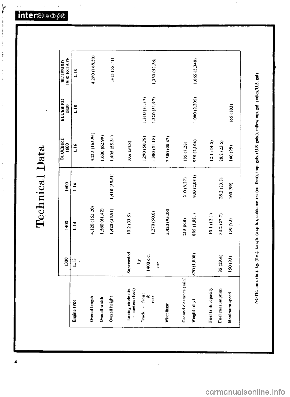
t
r
Engine
type
Ovendi
cngth
1300
L
13
Overall
width
Oyerall
height
Turning
circle
din
metres
tfeet
Supen
eded
by
Track
font
rear
1400
c
c
car
Ground
dearance
Olin
Weight
dry
I
820
808
I
Fuel
tClflk
capacity
35
29
6
150
93
Fuel
consumption
aximum
peed
Technical
Data
BLUEBIRD
400
1600
1600
U4
U6
0
4
120
162
20
1
560
6142
410
55
51
420
55
91
10
2
33
5
270
50
0
2
420
95
281
215
8
5
885
1
950
210
8
27
930
2
050
10
1
12
33
2
27
7
50
931
28
2123
5
60
99
L
16
4
215
165
941
1
600
62
99
405
55
3
Ii
0
6
34
8
290
50
79
1
300
51
18
2
500
98
43
185
7
281
955
2
1061
12
14
5
28
2
23
5
60
991
BLUEBIRD
1800
L
18
3
0
5
57
320
5
971
000
2
2051
165
103
BLUEBIRD
1800
ESTATE
U8
4
280
168
501
4
5
557
330
52
361
1
065
2
348
Page 14 of 171
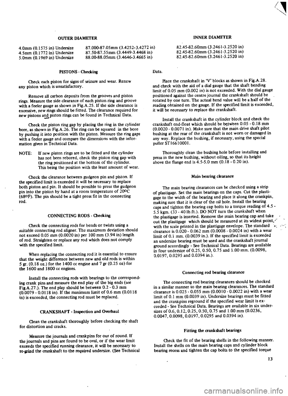
OUTER
DIAMETER
4
0mm
0
1575
in
Undersize
4
5mm
0
1772
in
Undersize
5
Omm
0
1969
in
Undersize
87
000
87
05mm
3
4252
3
4272
in
87
50
87
55mm
3
4449
3
4468
in
88
00
88
05mm
3
4646
3
4665
in
PISTONS
Checking
Check
each
piston
for
signs
of
seizure
and
wear
Renew
BIlY
piston
which
is
unsatisfactory
Remove
all
carbon
deposits
from
the
grooves
and
piston
rings
Measure
the
side
clearance
of
each
piston
ring
and
groove
with
a
feeler
gauge
as
shown
in
Fig
A
25
If
the
side
clearance
is
excessive
new
rings
should
be
fitted
The
clearance
required
for
new
pistons
a
piston
rings
can
be
found
in
Technical
Data
Check
the
piston
ring
gap
by
placing
the
ring
in
the
cylinder
bore
as
shown
in
Fig
A
26
The
ring
can
be
squared
in
the
bore
by
pushing
it
into
position
with
the
piston
Measure
the
ring
gaps
with
a
feeler
gauge
and
compare
the
dimensions
with
the
infor
mation
given
in
Technical
Data
NOTE
If
new
piston
rings
are
to
be
fitted
and
the
cylinder
has
not
been
rebafed
check
the
piston
ring
gap
with
the
ring
positioned
at
the
bottom
of
the
cylinder
This
being
the
position
with
the
least
amount
of
wear
O1eck
the
clearance
between
gudgeon
pin
and
piston
If
the
specified
limit
is
exceeded
it
will
be
necessary
to
replace
both
piston
and
pin
It
should
be
possible
to
press
the
gudgeon
pin
into
the
piston
by
hand
at
a
room
temperature
of
200C
680F
The
pin
should
be
a
tight
press
fit
in
the
connecting
rod
CONNECTING
RODS
O1ecking
Cleck
the
connecting
rods
for
bends
or
twists
using
a
guitable
connecting
rod
aligner
The
maximum
deviation
should
not
exceed
0
05
mm
0
0020
in
per
100
mm
3
94
in
length
of
rod
Straighten
or
replace
any
rod
which
does
not
comply
with
the
specified
limit
When
replacing
the
connecting
rod
it
is
essential
to
ensure
that
the
weight
difference
between
new
and
old
rods
is
within
5
gr
0
18
oz
for
the
1400
cc
engine
and
7
gr
0
25
oz
for
the
1600
and
1800
cc
engines
Install
the
connecting
rods
with
bearings
to
the
correspond
ing
crank
pins
and
measure
the
end
play
of
the
big
ends
s
e
Fig
A
27
The
end
play
should
be
between
0
2
0
3
mm
0
0079
0
0118
in
fthe
maximum
limit
of
0
6
mm
0
Ql18
in
is
exceeded
the
connecting
rod
must
be
replaced
CRANKSHAFT
Inspection
and
Overhaul
aean
the
crankshaft
thoroughly
before
checking
the
shaft
for
distortion
and
cracks
Measure
the
journals
and
crankpins
for
our
of
round
If
the
journals
and
pins
are
found
to
be
oval
or
if
the
wear
limit
exceeds
the
specified
fUnning
clearance
it
will
be
necessary
to
re
llrind
the
crankshaft
to
the
required
undersize
See
Technical
I
INNER
DIAMETER
82
45
82
60mm
3
24613
2520
in
82
4S
82
60mm
3
24613
2520
in
82
4S
82
60mm
3
24613
2520
in
Data
Place
the
crankshaft
in
V
blocks
as
shown
in
Fig
A
28
and
check
with
the
aid
of
a
dial
gauge
that
the
shaft
bending
limit
of
0
05
mm
0
002
in
is
not
exceeded
With
the
dial
gauge
positioned
against
the
centre
journal
the
crankshaft
should
be
rotated
by
one
turn
The
actual
bend
value
will
be
a
half
of
the
reading
obtained
on
the
gauge
If
the
specified
limit
is
exceeded
it
will
be
necessary
to
replace
the
crankshaft
Install
the
crankshaft
in
the
cylinder
block
and
check
the
crankshaft
end
float
which
should
be
be
J
Yieen
0
05
0
18
mm
0
0020
0
0071
in
Make
sure
that
the
main
drive
shaft
pilot
bushing
at
the
rear
of
the
crankshaft
is
not
worn
or
damaged
in
any
way
Replace
the
bushing
if
necessary
using
the
special
puller
STl
66
1000
I
Thoroughly
clean
the
bushing
hole
before
installing
and
press
in
the
new
bushing
without
oiling
so
that
its
height
above
the
flange
end
is
4
5
5
0
mm
0
18
0
20
in
Main
bearing
clearance
The
main
bearing
clearances
can
be
checked
using
a
strip
of
plastigage
Set
the
main
bearings
on
the
caps
Cut
the
plasti
gage
to
the
width
of
the
bearing
and
place
it
along
the
crankpin
making
sure
that
it
is
clear
of
the
oil
hole
Install
the
bearing
caps
and
tighten
the
bearing
cap
bolts
to
a
torque
reading
of
4
5
5
5
kgm
33
40
Ib
ft
DO
NOT
turn
the
crankshaft
when
the
plastigage
is
inserted
Remove
the
main
bearing
cap
and
take
out
the
plastigage
which
should
be
measured
at
its
widest
po
t
with
the
scale
printed
in
the
plastigage
envelope
The
standard
clearance
is
0
020
0
062
mm
0
0008
0
0024
in
with
a
wear
limit
of
0
1
mm
0
0039
in
If
the
specified
limit
is
exceeded
an
undersize
bearing
must
be
used
and
the
crankshaft
journal
ground
accordingly
See
Technical
Data
Bearings
are
available
in
four
undersize
of
0
25
0
50
0
75
and
1
00
mm
0
0098
0
0197
0
0295
and
0
0394
in
Connecting
rod
bearing
clearance
The
connecting
rod
bearing
clearances
should
be
checked
in
a
similar
manner
to
the
main
bearing
clearances
The
standard
clearance
is
0
025
0
055
mm
0
0010
0
0022
in
with
a
wear
limit
of
0
1
mm
0
0039
in
Undersize
bearings
must
be
fitted
and
the
crankpins
reground
if
the
specified
wear
limit
is
ex
ceeded
See
Technical
Data
Bearings
are
available
in
six
under
sizes
of
0
6
0
12
0
25
0
50
0
75
and
1
00
mm
0
0236
0
0047
0
0098
0
0197
0
0295
and
0
0394
in
Fitting
the
crankshaft
bearings
Cb
eck
the
fit
of
the
bearing
shells
in
the
following
manner
Install
the
shells
on
the
main
bearing
caps
and
cylinder
block
bearing
recess
and
tighten
the
cap
bolts
to
the
specified
torque
13
Page 21 of 171
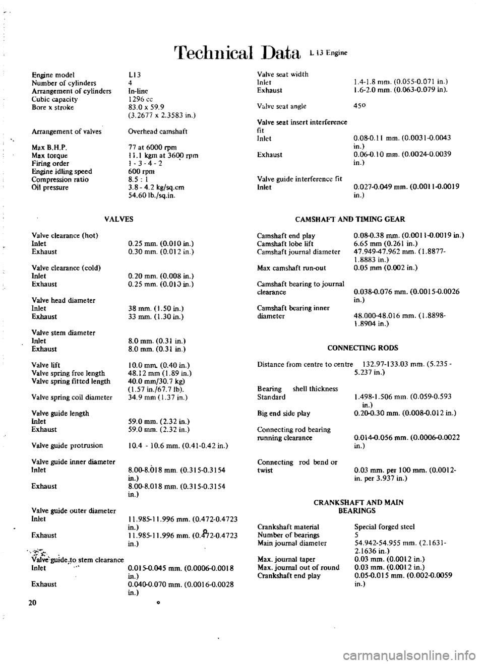
Engine
model
Number
of
cylinders
Arrangement
of
cylinders
Cubic
capaci
ty
Bore
x
stroke
Arrangemen
t
of
valves
Max
B
H
P
Max
torque
Firing
order
eidlingspeed
Compression
ratio
Oil
pressure
Valve
clearance
hot
Inlet
Exhaust
Valve
clearance
cold
Inlet
Exhaust
Valve
head
diameter
Inlet
Exhaust
Valve
stem
diameter
Inlet
Exhaust
Valve
lift
Valve
spring
free
length
Valve
spring
fitted
length
Valve
spring
coil
diameter
Valve
guide
length
Inlet
Exhaust
Valve
guide
protrusion
rreclll11cal
ata
L
lJEngine
LI3
4
In
line
1296
83
0
x
59
9
3
2677
x
3583
in
Overhead
camshaft
77
at
6000
rpm
II
1
kgm
at
3600
rpm
I
342
600
rpm
8
5
1
3
8
4
2
kg
sq
em
54
60Ib
sq
in
VALVES
0
25
mm
0
010
in
0
30
mm
0
01
in
0
20
mm
0
008
in
0
25
mm
O
OIJ
in
38
mm
1
50
in
33
mm
1
30
in
8
0
mm
0
31
in
8
0
mm
0
31
in
10
0
mm
0
40
in
48
12
mm
1
89
in
40
0
mm
30
7
kg
1
57
in
67
7
lb
34
9
mm
1
37
in
59
0
mm
2
32
in
59
0
mm
2
32
in
10
4
10
6
mm
0
41
0
42
in
Valve
guide
inner
diameter
Inlet
8
00
8
l
8
mm
0
315
0
3154
in
Exhaust
8
00
8
018
mm
0
315
0
3154
in
Valve
guide
outer
diameter
Inlet
Exhaust
Valve
guide
to
stem
clearance
Inlet
Exhaust
20
11
985
11
996
mm
0
472
0
4723
in
11
985
11
996
mm
0
4172
0
4723
in
0
015
0
045
mm
0
0006
0
0018
in
0
040
0
070
mm
0
0016
0
0028
in
Valve
seat
width
Inlet
Exhaust
V
lve
seat
angle
Valve
seat
insert
interference
fit
Inlet
Exhaust
Valve
guide
interference
fit
Inlet
1
4
1
8
mm
0
055
0
071
in
1
6
2
0
mm
0
063
0
079
in
450
0
08
0
11
mm
0
0031
0
0043
in
0
06
0
10
mm
0
0024
0
0039
in
0
027
0
049
mm
0
0011
0
0019
in
CAMSHAFT
AND
TIMING
GEAR
Camshaft
end
play
Camshaft
lobe
lift
Camshaft
journal
diameter
Max
camshaft
run
out
Camshaft
bearing
to
journal
clearance
Camshaft
bearing
inner
diameter
0
08
0
38
mm
0
0011
0
0019
in
6
65
mm
0
261
in
47
949
47
962
mm
fI
8877
1
8883
in
0
05
mm
0
002
in
0
038
0
076
mm
0
0015
0
0026
in
48
000
48
016
mm
1
8898
1
8904
in
CONNECTING
RODS
Distance
from
centre
to
centre
132
97
133
03
mm
5
235
5
237
in
Bearing
shell
thickness
Standard
Big
end
side
play
Connecting
rod
bearing
running
clearance
Connecting
rod
rend
or
twist
1
498
1
506
mm
0
059
0
593
in
0
20
0
30
mm
0
008
0
012
in
0
014
0
056
mm
0
0006
0
0022
in
0
03
mm
per
100
mm
0
0012
in
per
3
937
in
CRANKSHAFT
AND
MAIN
BEARINGS
Crankshaft
material
Number
of
bearings
Main
journal
diameter
Max
journal
taper
Max
journal
out
of
round
Crankshaft
end
play
Special
forged
steel
5
54
942
54
955
mm
2
1631
2
1636
in
0
03
mm
0
0012
in
0
03
mm
0
0012
in
0
05
0
015
mm
0
002
0
0059
in
Page 22 of 171
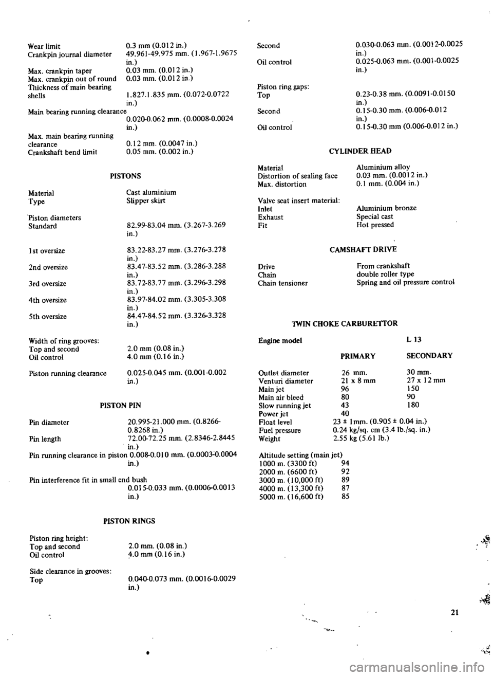
Wear
limit
Crank
pin
journal
diameter
Max
crankpin
taper
Max
crankpin
out
of
round
Thickness
of
main
bearing
shells
0
3
mm
0
012
in
49
961
49
975
mm
1
967
1
9675
in
0
03
mm
0
012
in
0
03
mm
0
012
in
1
827
1
835
mm
0
072
0
0722
in
Main
bearing
running
clearance
0
020
0
062
mm
0
0008
0
0024
in
Max
main
bearing
running
clearance
Crankshaft
bend
limit
Material
Type
Piston
diameters
Standard
I
st
oversize
2nd
oversize
3rd
oversize
4th
oversize
5th
oversize
Width
of
ring
grooves
Top
and
second
Oil
control
Piston
running
clearance
0
12
mm
0
0047
in
0
05
mm
0
002
in
PISTONS
Cast
aluminium
Slipper
skirt
82
99
83
04
mm
3
267
3
269
in
83
22
83
27
mm
3
276
3
278
in
83
47
83
52
mm
3
286
3
288
in
83
72
83
77
mm
3
296
3
298
in
83
97
84
02
mm
3
305
3
308
in
84
47
84
52
mm
3
326
3
328
in
2
0
mm
0
08
in
4
0
mm
0
16
in
0
025
0
045
mm
0
001
0
002
in
PISTON
PIN
Pin
diameter
20
995
21
000
mm
0
8266
0
8268
in
Pin
length
72
00
72
25
mm
2
8346
2
8445
in
Pin
running
clearance
in
piston
0
008
0
010
mm
0
0003
0
0004
in
Pin
interference
fit
in
small
end
bush
0
015
0
033
mm
0
0006
0
0013
in
Piston
ring
height
Top
and
second
Oil
control
Side
clearance
in
grooves
Top
PISTON
RINGS
2
0
mm
0
08
in
4
0
mm
0
16
in
0
040
0
073
mm
0
0016
0
0029
in
Second
Oil
control
Piston
ring
gaps
Top
Second
Oil
control
Material
Distortion
of
sealing
face
Max
distortion
Valve
seat
insert
material
Inlet
Exhaust
Fit
Drive
Chain
Chain
tensioner
0
030
0
063
mm
0
0012
0
0025
in
0
025
0
063
mm
0
001
0
0025
in
0
23
0
38
mm
0
0091
0
0150
in
0
15
0
30
mm
0
006
0
012
in
0
15
0
30
mm
0
006
0
012
in
CYLINDER
HEAD
Aluminium
alloy
0
03
mm
0
0012
in
0
1
mm
0
004
in
Aluminium
bronze
Special
cast
Hot
pressed
CAMSHAFT
DRIVE
From
crankshaft
double
roller
type
Spring
and
oil
pressure
control
Engine
model
lWIN
CHOKE
CARBURE
ITOR
Outlet
diameter
Venturi
diameter
Main
jet
Main
air
bleed
Slow
running
jet
Power
jet
Float
level
Fuel
pressure
Weight
Altitude
setting
main
jet
1000
m
3300
ft
94
2000
m
6600
ft
92
3000
m
10
000
ft
89
4000
m
13
300
ft
87
5000
m
16
600
ft
85
PRIMARY
L13
SECONDARY
30mm
27x
12mm
150
90
180
26
mm
21
x
8
mm
96
80
43
40
23
I
mm
0
905
0
04
in
0
24
kg
sq
em
3
41b
sq
in
2
55
kg
5
61
lb
1
21
Page 23 of 171
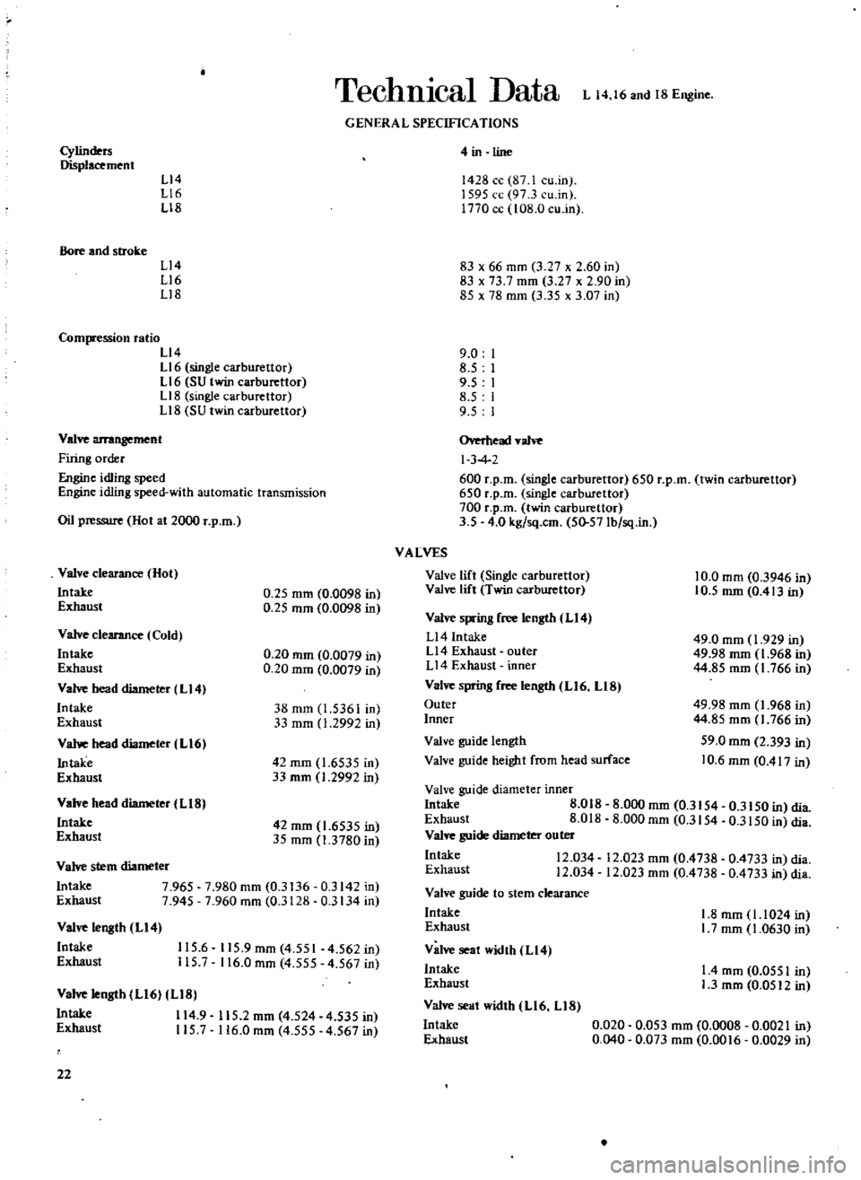
TechnIcal
Data
L
14
16
and
18
Engine
GENERAL
SPECIFICATIONS
Cylinders
Displacement
L14
L16
L18
Bore
and
stroke
L14
L16
Ll8
Compression
ratio
L14
L16
single
carburettor
L16
SU
twin
carburettor
L18
single
carburettor
Ll8
SU
twin
carburettor
Valve
arrangement
Firing
order
e
idling
speed
Engine
idling
speed
with
automatic
transmission
Oil
pressure
Hot
at
2000
r
p
m
Valve
clearance
Hot
Intake
Exhaust
0
25
mm
0
0098
in
0
25
mm
0
0098
in
Valve
clearance
Cold
Intake
Exhaust
Va
head
diameter
L14
Intake
Exhaust
Vahoe
head
diameter
L16
Intake
Exhaust
0
20
mm
0
0079
in
0
20
mm
0
0079
in
38
mm
1
5361
in
33
mm
1
2992
in
42
mm
1
6535
in
33
rom
1
2992
in
Valve
head
diameter
L18
Intake
Exhaust
42
mm
1
6535
in
35
mm
1
3780
in
Valve
stem
diameter
Intake
7
965
7
980
mm
0
3136
0
3142
in
Exhaust
7
945
7
960
mm
0
3128
0
3134
in
Valve
length
L14
Intake
Exhaust
115
6
115
9mm
4
551
4
562in
115
7
116
0
mm
4
555
4
567
in
Valve
length
L16
LIB
Intake
114
9
115
2
mm
4
524
4
535
in
Exhaust
115
7
116
0
mm
4
555
4
567
in
22
4
in
line
1428
cc
87
1
cu
in
1595
cc
97
3
cu
in
1770
cc
108
0
cu
in
83
x
66
mm
3
27
x
2
60
in
83
x
73
7
mm
3
27
x
2
90
in
85
x
7B
mm
3
35
x
3
07
in
9
0
8
5
9
5
8
5
9
5
Overhead
valve
I
3
4
600
r
p
m
single
carburettor
650
r
p
m
twin
carburettor
650
r
p
m
single
carburettor
700
r
p
m
twin
carburettor
3
5
4
0
kg
sq
cm
50
57Ib
sq
in
VALVES
Valve
lift
Single
carburettor
Valve
lift
Twin
carburettor
10
0
mm
0
3946
in
10
5
mm
0
413
in
Valve
spring
free
length
LI4
Ll4
Intake
Ll4
Exhaust
outer
L14
Exhaust
inner
Valve
sprin8
free
length
L16
LIB
Outer
Inner
49
0
mm
1
929
in
49
98
mm
1
968
in
44
85
mm
1
766
in
49
98
mm
1
968
in
44
85
mm
1
766
in
59
0
mm
2
393
in
10
6
mm
0
417
in
Valve
guide
length
Valve
guide
height
from
head
surface
Valve
guide
diameter
inner
Intake
8
018
Exhaust
8
018
Valve
guide
diameter
outer
Intake
12
034
Exhaust
12
034
Valve
guide
to
stem
clearance
Intake
Exhaust
Valve
seat
width
L14
Intake
Exhaust
Valve
seat
width
L16
LIB
Intake
Exhaust
8
000
mm
0
3154
0
3150
in
clia
8
000
mm
0
3154
0
3150
in
clia
12
023
mm
0
4738
0
4733
in
clia
12
023
mm
0
4738
0
4733
in
clia
1
8
mm
1
1024
in
I
7
mm
1
0630
in
I
4
mm
0
0551
in
1
3
mm
0
0512
in
0
020
0
053
mm
0
0008
0
0021
in
0
040
0
073
mm
0
0016
0
0029
in
Page 25 of 171
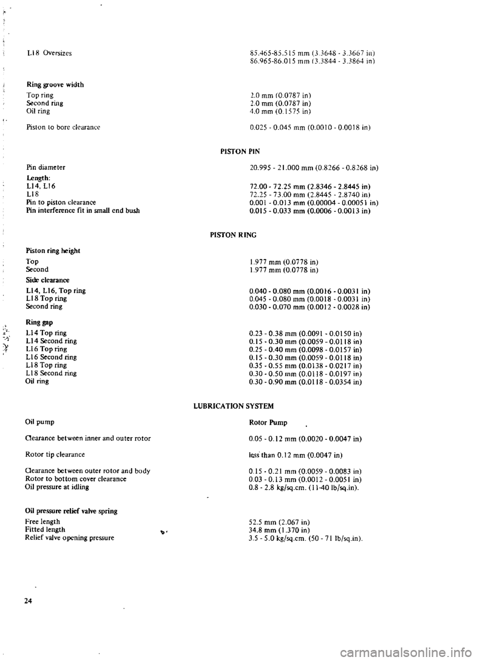
liB
Oversizes
Ring
groove
width
Top
ring
Second
ring
Oil
ring
Piston
to
bore
clearanl
e
Pin
diameter
I
ength
Ll4
Ll6
Ll8
Pin
to
piston
clearance
Pin
interference
fit
in
small
end
bush
Piston
ring
height
Top
Second
Side
clearance
Ll4
Ll6
Top
ring
LI8
Top
ring
Second
ring
Ring
gap
U4
Top
ring
U4
Second
ring
Ll6
Top
ring
L
16
Second
ring
U8
Top
ring
U8
Second
ring
Oil
ring
Oil
pump
Oearance
between
inner
and
outer
rotor
Rotor
tip
clearance
Oearance
between
outer
rotor
and
body
Rotor
to
bottom
cover
clearance
Oil
pressure
at
idling
Oil
pressure
relief
valve
spring
Free
length
Fitted
length
Relief
valve
opening
pressure
24
85465485
515
mm
3
648
667
ill
86
065
86
015
mm
13
3844
33864
in
0
mm
CO
0787
in
0
mm
0
0787
in
4
0
mm
0
1
q
c
in
0
025
0
045
mm
0
0010
0
0018
in
PISTON
PIN
20
995
1
000
mm
0
8266
0
8168
in
72
00
72
25
0
001
0
Dl5
72
25
mm
2
8346
2
8445
in
73
00
mm
2
8445
2
8740
in
0
013
mm
0
00004
0
00051
in
0
033
mm
0
0006
0
0013
in
PISTON
RING
1
977
mm
0
0778
in
1
977
mm
0
0778
in
0
040
0
080
mm
0
0016
0
0031
in
0
045
0
080
mm
0
0018
0
0031
in
0
030
0
070
mm
0
0012
0
0028
in
0
23
0
38
mm
0
0091
0
0150
in
0
15
0
30
mm
0
0059
0
0118
in
0
25
0
40
mm
0
0098
0
0157
in
0
15
0
30
mm
0
0059
0
0118
in
0
35
0
55
mm
0
0138
0
0217
in
0
30
0
50mm
0
0118
0
0197
in
0
30
0
90
mm
0
0118
0
0354
in
LUBRICATION
SYSTEM
Rotor
Pump
0
05
0
12
mm
0
0020
0
0047
in
less
than
0
12
mm
0
0047
in
0
15
0
21
mm
0
0059
0
0083
in
0
03
0
13
mm
0
0012
0
0051
in
0
8
2
8
kg
sq
cm
11
40
Ib
sq
ln
52
5
mm
2
067
in
34
8
mm
1
370
in
3
5
5
0
kg
sq
cm
50
71
Ib
sq
ln
Page 28 of 171
The
thermostat
can
be
tested
by
suspending
it
with
a
thermometer
in
a
container
ftlled
with
water
Heat
the
water
gradually
and
stir
it
to
obtain
a
uniform
temperature
Maintain
a
constant
check
of
the
temperature
and
make
sure
that
neither
the
thermostat
or
thermometer
touch
the
sides
of
the
container
or
false
readings
will
be
obtained
The
thermostat
should
begin
to
open
at
a
temperature
of
820C
1
50C
179
60F
2
70Fj
and
should
be
fully
open
with
a
maximum
valve
lift
of
8
mm
0
315
in
at
a
temperature
of
950C
2030F
When
installing
the
thermostat
apply
adhesive
to
both
sides
of
the
gasket
before
refitting
the
water
outlet
elbow
RADIATOR
Removal
Drain
the
cooling
system
as
previously
described
and
remove
the
front
grille
2
Disconnect
the
radiator
upper
hose
lower
hose
and
hose
to
the
reservoir
tank
3
Remove
the
radiator
securing
bolts
and
lift
out
the
radiator
Fig
B
4
It
should
be
noted
that
cars
fitted
with
automatic
transmission
incorporate
a
transmission
oil
cooler
which
must
be
disconnected
Installation
is
a
reversal
of
the
removal
procedure
refill
the
system
as
previously
described
FLUID
COUPLING
The
water
pump
is
equipped
with
a
fluid
coupling
on
vehicles
fitted
with
an
air
conditioner
The
fluid
coupling
Limits
the
maximum
fan
speed
to
approximately
3000
r
p
ro
and
eliminates
noise
and
loss
of
power
at
high
engine
speeds
A
fault
in
the
coupling
may
be
caused
by
the
entry
of
foreign
matter
If
a
fault
developes
the
oupling
must
be
removed
and
dismantled
and
the
interior
cleaned
by
washing
in
solvent
The
condition
of
the
seal
and
bearing
must
be
care
fully
checked
and
the
coupling
replaced
if
the
latter
items
have
become
blackened
If
oil
leaks
occur
it
will
be
necessary
to
replace
the
water
pump
assembly
with
the
coupling
After
cleaning
the
unit
refill
with
11
5
cc
silicon
oil
using
a
suitable
syringe
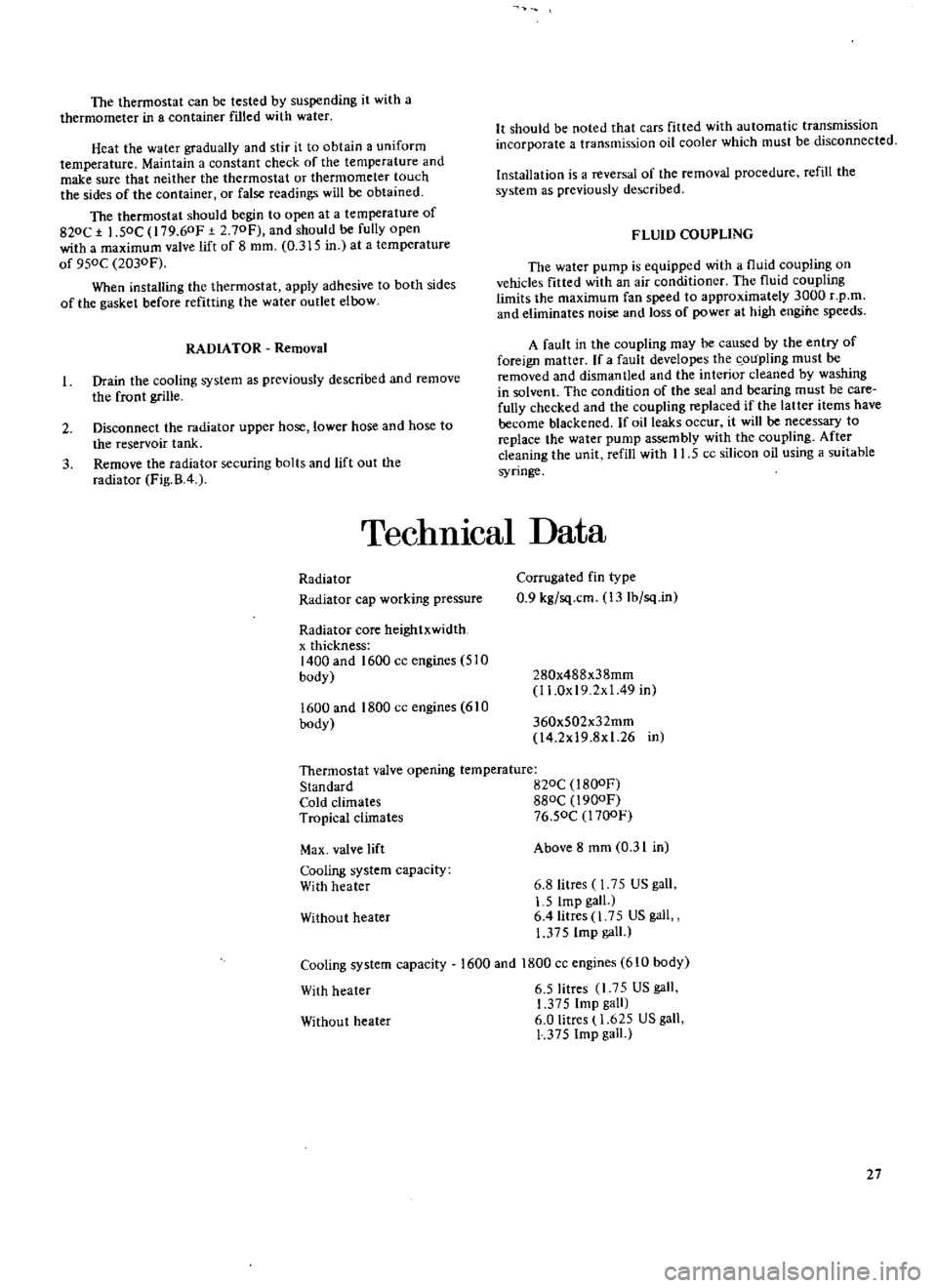
TechnIcal
Data
Radiator
Radiator
cap
working
pressure
Radiator
core
heightxwidth
x
thickness
1400
and
1600
cc
engines
510
body
1600
and
1800
cc
engines
610
body
Corrugated
fin
type
0
9
kg
sq
cm
13Ib
sq
in
280x488x38mm
I
LOx
19
2x
1
49
in
360x502x32mm
l4
2x19
8x1
26
in
Thermostat
valve
opening
temperature
Standard
B20C
l
BOOF
Cold
climates
880C
1900F
Tropical
climates
76
50C
l700F
Max
valve
lift
Cooling
system
capacity
With
heater
Without
heater
Cooling
system
capacity
With
heater
Above
8
mm
0
31
in
6
8litres
1
75
US
gall
1
5
Imp
gall
6
4litres
1
75
US
gall
1
375
Imp
gall
1600
and
1800
cc
engines
610
body
6
5litres
l
7
US
gall
1
375
Imp
gall
6
0
Iitres
1
625
US
gall
1
375
Imp
gall
Without
heater
27
Page 68 of 171
cage
Mcasure
the
clearance
between
the
rear
face
of
thc
side
gear
and
the
differential
cage
as
shown
in
Fig
G
ll
and
if
necessary
use
a
tluust
washer
which
will
given
a
clearance
of
0
1
0
2mm
0
004
0
008
in
Fit
the
pinion
shaft
lock
pin
and
secure
it
by
caulking
with
a
punch
Lubricate
the
gear
teeth
and
check
the
gear
for
freedom
of
rotation
Install
the
crown
wheel
in
the
differential
cage
and
insert
the
bolts
with
new
lock
straps
Tap
the
head
of
each
bolt
lightly
and
tighten
the
bolts
in
a
diagonal
pattern
to
a
torque
reading
of
7
0
8
0
kgm
51
58Ib
ft
Measure
the
width
of
the
side
bearings
before
installing
them
Place
a
weight
of
2
5
kg
5
5
1b
on
the
bearings
and
check
the
nominal
width
which
should
be
20mm
0
787
in
Press
the
side
bearings
into
the
differential
cage
Adjustment
of
drive
pinion
preload
This
adjustment
is
carried
out
without
fitting
the
oil
seal
Press
the
front
and
rear
bearing
outer
races
into
the
gear
carrier
and
fit
the
pinion
height
adjusting
washer
Fig
G
12
the
shims
and
the
rear
bearing
inner
race
onto
a
dummy
shaft
special
tool
ST
31
120000
The
old
washers
and
shims
can
be
re
used
if
the
tooth
contact
pattern
was
found
to
be
correct
on
the
pre
dismantling
check
Fit
the
drive
pinion
bearing
spacer
the
washer
ans
special
collar
5T
312140000
or
5T
31500000
and
the
drive
flange
on
to
the
dummy
shaft
Tighten
the
drive
pinion
nut
to
a
torque
reading
of
17
20
kgm
123
145
Ib
ft
Measure
the
drive
pinion
bearing
pre
load
and
select
washers
and
spacers
to
give
a
pre
load
of
7
1
0
kg
cm
6
9Ib
in
with
new
bearings
or
3
6
kg
cm
2
6
5
Ib
in
with
used
bearings
Adjusting
spacers
are
available
in
lengths
of
56
2
57
2
mm
2
2126
2
2520
in
and
adjusting
washers
in
thicknesses
of
59
2
31
mm
0
1020
0
0909
in
Adjustment
of
pinion
height
The
pinion
height
or
distance
of
the
face
of
the
pinion
to
the
axis
of
the
crownwheel
is
adjusted
by
the
thickness
of
the
adjusting
washer
behind
the
drive
pinion
gcar
The
drive
pinion
has
a
tolerance
mark
etched
on
its
face
this
tokrance
is
accompanied
by
a
or
sign
to
show
the
deviation
from
the
nominal
dimension
Thc
plus
sign
indicates
that
the
nominal
distance
must
be
increased
and
the
minus
sign
that
it
mllst
be
decreased
The
tolerances
are
shown
in
Fig
G
I3
The
pinion
height
can
be
adjusted
using
the
original
adjusting
washer
and
shims
between
the
rear
bearing
cone
and
the
drive
pinion
Install
the
setting
gauge
5T
31210000
on
the
carrier
with
the
dummy
pinion
installed
Sce
Fig
G
14
Measure
the
clearance
between
the
head
of
the
dummy
shaft
and
the
tip
of
the
setting
g
wge
using
a
feeler
gauge
as
shown
in
Fig
G
15
The
clearance
is
also
shown
at
the
point
T
in
Fig
G
14
The
required
thickness
of
the
adj
lsting
washer
can
be
obtained
using
the
following
formula
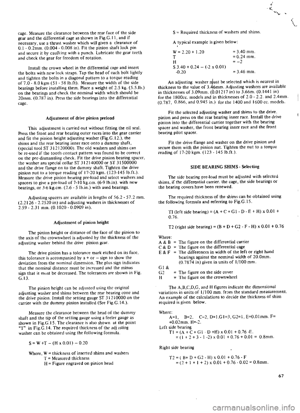
S
W
T
H
x
0
01
0
20
Where
W
thickness
of
inserted
shims
and
washers
T
Measured
thickness
H
Figure
engraved
on
pinion
head
o
S
Required
thickn
ss
of
washers
and
shims
A
typical
example
is
given
below
w
20
1
20
T
H
S
340
0
24
2
x
0
01
0
20
3
40
mm
0
24
mm
3
46
mm
An
adjusting
washer
rrlust
be
selected
which
is
nearest
in
thickness
to
the
value
of
3
46mm
Adjusting
washers
are
available
in
thicknesses
of
3
09mm
0
01217
in
to
3
66m
0
1441
in
for
the
l800cc
models
and
in
thicknesses
of
O
2
and
2
4mm
0
787
0
866
and
0
945
in
for
the
1400
and
1600
cc
models
Fit
the
selected
adjusting
washer
and
shims
to
the
drive
pinion
and
press
on
the
rear
bearing
inner
race
Install
the
drive
pinion
into
the
differential
carrier
together
with
the
bearing
spacer
and
washer
the
front
bearing
inner
race
and
the
front
bearing
pilot
spacer
Fit
the
drive
flange
and
washer
on
the
drive
pinion
and
secure
them
with
the
pinion
nut
Tighten
the
nut
to
a
torque
reading
of
17
20
kgm
123
145Ib
ft
SIDE
BEARING
SHIMS
Selecting
The
side
bearing
pre
load
must
be
adjusted
with
selected
shims
if
the
differential
carrier
the
cage
the
side
bearings
or
the
bearing
covers
have
been
renewed
The
required
thickness
of
the
shims
can
be
obtained
using
the
following
formula
and
referring
to
Fig
G
l
5
T1
left
side
bearing
A
C
GI
D
E
H
x
0
01
0
76
T2
right
side
bearing
B
D
G2
F
H
x
0
01
0
76
Where
A
B
C
D
E
F
The
figure
on
the
differential
carrier
The
figure
on
the
differential
cage
The
differences
in
width
of
the
left
or
right
hand
bearings
against
the
nominal
width
of
20
0mm
0
7874
in
given
in
units
of
1
100
mm
Gl
G2
H
The
figure
on
the
side
cover
The
figure
on
the
crownwheel
The
A
B
C
D
G
and
H
figures
indicate
the
dimensional
variations
in
units
of
1
100
mm
fr
Jm
the
standard
measurement
An
example
of
the
calculations
to
decide
the
thickness
of
shim
required
is
given
below
Where
A
I
B
2
C
2
D
1
GI
3
G2
1
E
O
Olmm
F
O
02mm
H
Left
side
bearing
Tl
A
C
G
1
D
H
x
0
01
0
76
E
I
3
1
2
x
0
01
0
76
0
01
0
8mm
Right
side
bearing
T2
B
D
G2
H
x
0
01
0
76
F
2
I
I
2
x
0
01
0
76
0
02
0
8mm
67
Page 70 of 171
The
standard
width
of
the
side
bearings
is
20
0mm
0
7874
this
width
must
be
measured
before
attempting
to
calculate
the
thickness
of
the
adjusting
shims
Use
a
dial
gauge
and
surface
plate
to
ohtain
the
measurement
Place
a
weight
of
approximately
2
5
kg
5
5
lb
on
the
bearing
to
obtain
steady
readings
Install
the
differential
cage
assembly
in
the
carrier
Fit
the
sckcted
shims
and
O
rings
into
both
differential
side
bearing
covers
and
install
the
covers
in
the
carrier
using
the
special
tool
ST
33720000
Fig
G
16
l
Make
sure
that
the
side
bearing
outer
races
are
not
damaged
by
the
roller
Measure
the
backlash
between
the
teeth
of
the
crown
wheel
and
drive
pinion
with
a
dial
gauge
as
shown
in
Fig
G
I
Sct
the
dial
gauge
to
0
10
f
O
mm
0
004
0
008
in
I
If
the
backlash
is
less
than
the
specifIed
value
move
he
left
side
adjusting
shim
to
the
right
side
and
vice
versa
if
the
backlash
exceeds
the
specified
figure
Check
that
the
run
out
at
the
rear
of
the
crownwheel
does
not
excecd
O
OSmm
0
002
in
for
the
1800ce
model
or
O
08mm
0
003
in
for
the
1400
Check
the
drive
pinion
turning
torque
Thc
turning
torque
should
be
higher
by
I
3
kg
em
compared
with
the
turning
torque
obtained
before
fitting
the
differential
cage
in
the
carrier
The
higher
value
can
be
provided
if
necessary
by
dmnging
the
jde
cover
shims
Note
howcver
that
any
decrease
or
increase
in
the
thickncss
of
shims
wjJl
alter
tht
budlush
between
the
teeth
of
the
crownwhee1
and
pinion
Check
the
tooth
contact
pat
tern
of
the
crown
wheel
and
pinion
as
described
under
the
appropriate
heading
DIFFERENTIAL
Installation
Secure
the
differential
carrier
on
the
rear
suspension
mem
ber
using
the
four
bolts
and
washers
Fit
the
differential
mounting
member
to
thc
mounting
holes
by
pushing
it
forwards
with
a
suitable
lever
Fig
G
18
Tighten
the
nuts
to
a
torque
reading
of
8
5
kgm
61
5
Ib
ft
Tighten
the
bolts
attaching
the
gear
carrier
to
the
suspension
member
to
a
torque
reading
of
6
7
kg
36
5Ilb
ft
t
The
rcmainder
of
the
installation
operations
are
a
reversal
of
thc
removal
procedure
Fill
the
differential
with
the
correct
quantity
of
recommended
oil
DIFFERENTIAL
CARRIER
Removal
and
Dismantling
Estate
car
alld
Vanl
To
remove
the
differential
carrier
disconnect
and
remove
rhe
propeller
shaft
as
previously
described
and
remove
the
two
rear
axle
shafts
as
described
in
the
section
REAR
AXLL
With
draw
the
nuts
securing
the
differential
and
remove
the
carrier
from
the
rear
axle
Mount
the
unit
on
the
special
attachment
as
shown
in
Fig
G
19
and
carry
out
a
preliminary
check
before
dismantling
Oleck
the
tooth
contact
of
the
crownwheel
and
pinion
by
applying
lead
oxide
to
three
or
four
teeth
of
the
crownwheel
Turn
the
crown
wheel
several
times
to
obtain
an
impression
of
the
tooth
contact
pattern
Check
the
backlash
between
the
teeth
of
the
crownwheel
and
pinion
with
a
dial
gauge
Hold
the
drive
pinion
with
one
hand
and
move
the
crown
wheel
backwards
and
forwards
to
check
that
the
backlash
is
Io
ithin
thL
speL
ified
limits
Shims
and
adjusting
washers
must
bL
altered
if
the
tooth
con
tact
pattern
and
backlash
is
incorre
L
the
neL
cssary
details
for
these
operations
can
be
found
towards
the
end
of
this
section
under
the
appropriate
he
Jdjn
s
Fil1JJly
mark
the
bearing
caps
with
a
hammer
and
punch
to
ensure
correct
t1ignment
on
re
assembly
Remove
the
bearing
caps
nd
withdraw
the
differ
ntial
cage
make
a
note
of
the
left
and
right
hand
positions
so
h
Jt
the
bearing
caps
and
outer
race
can
be
re
assembled
in
their
original
positions
Withdraw
the
side
beJrings
with
the
s
cjal
puller
as
shown
in
Fig
G
20
taking
care
not
to
catch
the
edge
of
the
bearing
inner
races
Place
the
assembly
in
a
vice
and
detach
the
crownwheel
by
slackening
the
retaining
bolts
in
a
diagonal
patter
Fig
G
lf
Drive
out
th
pinion
shaft
lock
pin
from
left
to
right
using
a
suitable
punch
or
special
tool
ST
23520000
Fig
C
22
With
draw
the
pinion
shaft
and
take
out
the
pinions
side
gears
and
thrust
washers
Store
the
gears
and
thrust
washers
so
that
they
can
be
assembled
in
their
original
positions
Check
the
initial
turning
torque
of
the
drive
pinion
with
the
preload
gauge
ST
3190000
and
measure
the
height
of
the
drive
pinion
with
the
special
gauge
ST
31941000
Compare
the
figures
obtained
with
those
givcn
in
Technical
Data
at
the
end
of
this
section
Hold
the
drive
pinion
with
the
speciaJ
wrench
ST
3
J
530000
as
shown
in
Fig
C
23
and
unscrew
the
drivc
pinion
nut
then
pull
out
the
drive
pjnion
flange
Tap
the
drive
pinion
assembly
to
the
rear
with
a
plastic
mallet
and
withdraw
it
together
with
the
rear
bearing
inner
race
bearing
spacer
and
adjusting
washer
Remove
and
discard
the
oil
seal
and
withdraw
thc
front
bearing
inner
race
Drive
out
the
outer
races
of
the
front
and
rear
bearings
with
a
suitable
drift
Fig
G
25
The
drive
pinion
rear
bearing
inncr
race
can
be
removed
with
the
special
tool
ST
300310000
as
shown
in
Fig
G
24
DIFFE
l
ENTlAL
Inspection
Clean
all
components
thoroughly
and
examine
for
signs
of
wear
or
damage
Check
the
teeth
of
the
crownwhcel
and
pinion
for
scoring
and
hipping
Ii
should
be
noted
that
the
crownwhecl
and
pinion
are
supplied
as
a
matched
set
and
if
either
part
is
damaged
the
complete
set
must
be
replaced
Examine
the
inner
faces
of
the
side
gears
and
seats
on
the
differential
case
Inspect
the
bearing
races
and
rollers
and
replace
them
if
necessary
Small
defects
on
the
faces
of
the
thrust
washers
can
be
corrected
using
emery
cloth
however
if
the
clearance
between
side
gear
and
thrust
washer
exceeds
0
1
O
2mm
0
0039
0
0079
in
it
ill
be
necessary
to
replace
the
washer
Various
sizes
of
washers
are
available
and
the
thicknesses
arc
detailed
under
the
heading
DIFFERENTIA
L
GEAR
CAGE
Assembling
69
Page 72 of 171
greased
Install
the
flange
washer
and
pinion
nut
Tighten
the
nut
to
a
torque
reading
of
14
17
kgm
101
130
Ib
fL
If
the
cotter
pin
hole
is
not
correctly
aligned
a
suitable
washer
should
be
fitted
Do
NOT
adjust
by
overtightening
the
pinion
nul
Van
Lubricate
the
front
bearing
with
oil
and
place
it
in
the
carrier
Grease
the
lip
of
the
oil
seal
and
install
it
to
the
final
drive
housing
Install
the
drive
pinion
the
new
collapsible
spacer
and
the
drive
flange
Fit
the
drive
pinion
nut
and
tighten
temporarily
until
all
slackness
is
eliminated
from
the
front
and
rear
of
the
drive
pinion
NOTE
Ensure
that
oil
and
grease
have
been
completely
removed
from
the
threads
of
the
pinion
gear
the
pinion
nut
and
the
washer
Tighten
the
pinion
nut
and
check
the
preload
with
a
preload
gauge
As
the
nut
is
tightened
to
the
specified
torque
reading
of
13
20
kgm
94
0
144
6Ib
fL
the
preload
must
be
measured
at
every
five
to
ten
degrees
turn
of
the
pinion
nut
As
the
pinion
nut
is
tightened
the
stepped
portion
of
the
spacer
is
deformed
See
Fig
G
29
J
and
the
length
between
the
bearings
adjusted
The
drive
pinion
bearing
preload
with
oil
seal
and
new
bearing
is
7
15
kg
cm
6
1
13
0
lb
in
Turn
the
drive
pinion
to
settle
the
bearing
and
re
check
the
preload
and
tightening
torque
If
the
preload
rate
is
exceeded
it
will
be
necessry
to
fit
a
new
spacer
the
old
spa
cr
cannot
be
reused
and
the
preload
must
not
be
adjusted
by
loosening
the
pinion
nul
Side
bearing
pre
load
adjusting
If
the
original
side
bearings
arc
to
be
used
the
shims
must
be
of
the
same
thickness
as
those
previously
fitted
To
select
shims
for
new
side
bearings
proceed
as
follows
The
standard
width
of
the
side
bearings
is
given
in
Technical
Data
This
width
must
be
measured
before
attempting
to
calculate
the
required
thickness
of
the
adjusting
shims
Place
a
weight
of
approximately
5
kg
5
5
lb
and
of
predetermined
height
onto
the
side
bearing
as
shown
in
Fig
G
30
Mcasure
the
width
of
the
bearing
with
a
dial
gauge
as
illustrated
turning
the
bearing
two
or
three
times
to
gain
an
accurate
meaSurement
Dimensional
variations
from
the
standard
measurements
are
marked
on
the
left
side
bearing
housing
of
the
gear
carrier
on
the
right
side
bearing
housing
of
the
gear
carrier
and
on
the
differential
case
These
variations
are
marked
in
units
of
l
lOOmm
and
are
used
for
the
f
rmula
to
calculate
t1H
thickness
of
the
adjusting
shims
in
the
following
manner
Where
TI
equals
the
left
side
bearing
shim
crownwhecl
side
T2
equals
the
right
side
bearing
shim
pinion
gear
A
equals
the
figure
marked
on
the
left
side
bearing
housing
B
equals
the
figure
marked
on
the
right
side
bearing
housing
C
and
0
equals
the
figure
marked
on
the
differential
case
and
E
and
F
is
the
difference
bctween
the
width
of
the
side
bearings
and
the
standard
bearing
width
H
the
figure
marked
on
the
crownwhcel
Fig
G
31
The
following
formulae
can
now
be
used
to
deter
mine
the
required
shim
thicknessl
s
for
both
side
bearings
I
OOcc
Estate
car
Left
side
bearing
TI
A
C
D
H
x
0
01
0
100
E
Right
side
bearingT2
B
D
H
x
0
01
0
090
F
I800cc
Van
Left
side
bearingTI
A
C
D
H
xO
OI
0
175
E
Right
side
bcaringT2
8
D
H
x
0
01
0
150
F
As
an
example
where
A
1
B
C
2
D
3
E
0
02mm
H
I
The
formula
for
the
left
side
bearing
is
T
I
I
1
3
1
x
0
01
0
175
0
02
0
205mm
1400
and
1600cc
Estate
car
The
required
thickness
of
shim
can
be
found
using
the
following
formula
in
a
similar
manner
to
that
previously
described
for
the
1800cc
models
Left
side
bearing
T
I
A
C
D
E
7
Right
side
bearing
T2
B
D
F
6
Shims
are
available
in
five
thicknesses
of
0
05
0
07
0
10
0
20
and
0
50
mm
0
002
0
0028
0
0039
0
0079
and
0
0197
in
Fit
the
selected
side
bearing
adjusting
shims
on
the
differential
cage
and
press
in
the
side
bearing
inner
races
using
a
suitable
ddfL
nstall
the
differential
cage
into
the
carrier
and
fit
the
bearing
caps
Ensure
that
the
marks
on
the
caps
coincide
with
the
marks
on
the
carrier
Tighten
the
bearing
cap
bolts
to
the
specified
torque
reading
See
Tighte
ing
torques
Measure
the
dimension
between
the
outer
edges
of
the
left
and
right
hand
caps
using
a
large
micrometer
as
shown
in
Fig
G
32
This
dimension
should
be
198
40
198
55
mm
7
8110
7
8169
in
for
the
1400
and
1600
ce
Estate
cars
and
1800
ce
Van
and
173
23
17329
mm
6
8201
6
8244
inl
for
the
1800
cc
Estate
cars
Measure
the
backlash
of
the
crownwhcel
and
pinion
with
a
dial
gauge
The
backlash
must
be
adjusted
to
0
13
0
18
mm
0
005
0
007
in
on
the
1800
CC
models
and
to
0
15
0
20mm
0
006
0
008
in
on
the
1400
and
1600
cc
models
Adjustment
can
be
carried
out
by
moving
side
bearing
shims
from
the
right
hand
side
to
the
left
hand
side
if
the
backlash
is
too
high
or
vice
verca
if
the
backlash
is
too
low
Tighten
the
bearing
cap
bolts
to
the
specified
torque
reading
after
adjusting
Ensure
that
the
run
out
at
the
rear
of
the
crown
wheel
does
not
exceed
O
05mm
0
002
in
Finally
heck
the
tooth
contact
pattern
as
described
below
TOOTH
CONTACT
PATTERN
Checking
The
final
check
on
reassembly
is
an
inspection
of
the
tooth
contact
markings
of
the
crownwhed
and
pinion
Apply
a
coal
of
red
lead
in
oil
to
4
or
5
teeth
of
the
crown
wheel
Turn
the
crownwheel
backwards
and
forwards
several
times
to
obtain
a
clear
impression
of
the
contact
areas
Heel
contact
Fig
G
3
1
71