wipers DATSUN 610 1969 Workshop Manual
[x] Cancel search | Manufacturer: DATSUN, Model Year: 1969, Model line: 610, Model: DATSUN 610 1969Pages: 171, PDF Size: 10.63 MB
Page 110 of 171

ElectrIcal
EquIpment
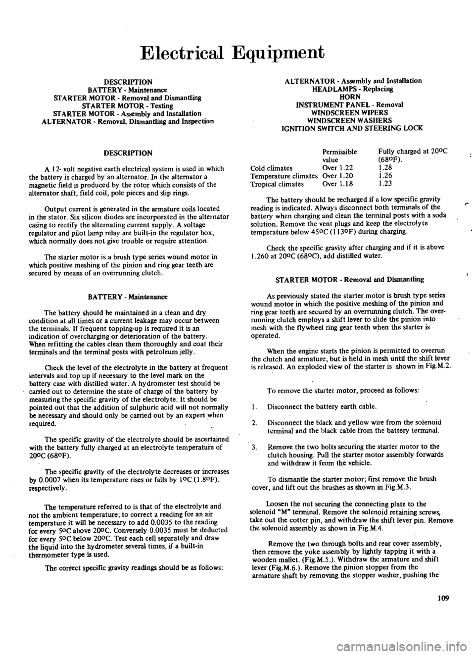
DESCRIPTION
BATTERY
Maintenance
STARTER
MOTOR
Removal
and
Dismantling
STARTER
MOTOR
Testing
STARTER
MOTOR
Assembly
and
Installation
ALTERNATOR
Removal
Dismantling
and
Inspection
DESCRIPTION
A
12
volt
negative
earth
electrical
system
is
used
in
which
the
battery
is
charged
by
an
alternator
In
the
alternator
a
magnetic
field
is
produced
by
the
rotor
which
consists
of
the
alternator
shaft
field
coil
p
le
pieces
and
slip
rings
Output
current
is
generated
in
the
armature
coils
located
in
the
stator
Six
silicon
diodes
are
incorporated
in
the
alternator
caSing
to
rectify
the
alternating
current
supply
A
voltage
regulator
and
pilot
lamp
relay
are
built
in
the
regulator
box
which
nonnally
does
not
give
trouble
or
require
attention
The
starter
motor
is
a
brush
type
series
wound
motor
in
which
positive
meshing
of
the
pinion
and
ring
gear
teeth
are
secured
by
means
of
an
overrunning
clutch
BATTERY
Maintenance
The
battery
should
be
maintained
in
a
clean
and
dry
condition
at
all
times
or
a
current
leakage
may
occur
between
the
terminals
If
frequent
topping
up
is
required
it
is
an
indication
of
overcharging
or
deterioration
of
the
battery
When
refitting
the
cables
clean
them
thoroughly
and
coat
their
terminals
and
the
terminal
posts
with
petroleum
jelly
Check
the
level
of
the
electrolyte
in
the
battery
at
frequent
intervals
and
top
up
if
necessary
to
the
level
mark
on
the
battery
case
with
distilled
water
A
hydrometer
test
should
be
carried
out
to
determine
the
state
of
charge
of
the
battery
by
measuring
the
specific
gravity
of
the
electrolyte
It
should
be
pointed
out
that
the
addition
of
sulphuric
acid
will
not
normally
be
necessary
and
should
only
be
carried
out
by
an
expert
when
required
The
specific
gravity
of
the
electrolyte
should
be
ascertained
with
the
battery
fully
charged
at
an
electrolyte
temperature
of
200C
680F
The
specific
gravity
of
the
electrolyte
decreases
or
increases
by
0
0007
when
its
temperature
rises
or
falls
by
10C
1
80F
respectively
The
temperature
referred
to
is
that
of
the
electrolyte
and
not
the
ambient
temperature
to
correct
a
reading
for
an
air
temperature
it
will
be
necessary
to
add
0
0035
to
the
reading
for
every
50C
above
200C
Conversely
0
0035
must
be
deducted
for
every
SOC
below
200C
Test
each
cell
separately
and
draw
the
liquid
into
the
hydrometer
several
times
if
a
built
in
thermometer
type
is
used
The
correct
specific
gravity
readings
should
be
as
follows
ALTERNATOR
Assembly
and
Installation
HEAD
LAMPS
Replacing
HORN
INSTRUMENT
PANEL
Removal
WINDSCREEN
WIPERS
WINDSCREEN
WASHERS
IGNITION
SWITCH
AND
STEERING
LOCK
Cold
climates
Temperature
climates
Tropical
climates
Permissible
value
Over
1
22
Over
1
20
Over
1
18
Fully
charged
at
200C
680F
1
28
1
26
1
23
The
battery
should
be
recharged
if
a
low
specific
gravity
reading
is
indicated
Always
disconnect
both
terminals
of
the
battery
when
charging
and
clean
the
terminal
posts
with
a
soda
solution
Remove
the
vent
plugs
and
keep
the
electrolyte
temperature
below
450C
l130F
during
charging
Check
the
specific
gravity
after
charging
and
if
it
is
above
1
260
at
200C
680C
add
distilled
water
STARTER
MOTOR
Removal
and
Dismantling
As
previously
stated
the
starter
motor
is
brush
type
series
wound
motor
in
which
the
positive
meshing
of
the
pinion
and
ring
gear
teeth
are
secured
by
an
overrunning
clutch
The
over
running
clutch
employs
a
shift
lever
to
slide
the
pinion
into
mesh
with
the
flywheel
ring
gear
teeth
when
the
starter
is
operated
When
the
engine
starts
the
pL
lion
is
permitted
to
overrun
the
clutch
and
armature
but
is
held
in
mesh
until
the
shift
lever
is
released
An
exploded
view
of
the
starter
is
shown
in
Fig
M
2
To
remove
the
starter
motor
proceed
as
follows
Disconnect
the
battery
earth
cable
2
Disconnect
the
black
and
yellow
wire
from
the
solenoid
terminal
and
the
black
cable
from
the
battery
terminal
3
Remove
the
two
bolts
securing
the
starter
motor
to
the
clutch
housing
Pull
the
starter
motor
assembly
forwards
and
withdraw
it
from
the
v
hicle
To
dismantle
the
starter
motor
ftrst
remove
the
brush
cover
and
lift
out
the
brushes
as
shown
in
Fig
M
3
Loosen
the
nut
securing
the
connecting
plate
to
the
solenoid
M
terminal
Remove
the
solenoid
retaining
screws
take
out
the
cotter
pin
and
withdraw
the
shift
lever
pin
Remove
the
solenoid
assembly
as
shown
in
Fig
M
4
Remove
the
two
through
bolts
and
rear
cover
assembly
then
remove
the
yoke
assembly
by
lightly
tapping
it
with
a
wooden
mallet
Fig
M
S
Withdraw
the
armature
and
shift
lever
Fig
M
6
Remove
the
pinion
stopper
from
the
armature
shaft
by
removing
the
stopper
washer
pushing
the
109
Page 117 of 171

inter
@IP
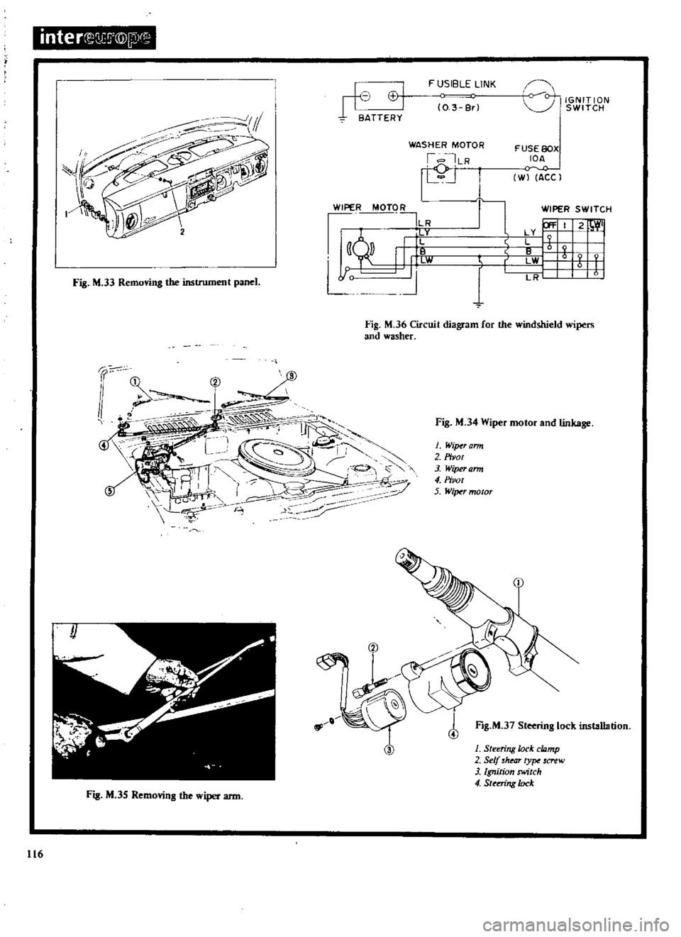
Fig
M
33
Removing
the
instrument
panel
h
J
I
II
VI
BATTERY
FUSIBLE
LINK
0
3
Br
WASHER
MOTOR
I
ILR
rj
WIPER
MOTO
R
ILR
lity
111
W
J
9P
l
l
0
0
IGNITION
SWITCH
FUSE
BOX
IDA
0
W
ACC
r
WIPER
SWITCH
P
I
2
W
I
X
9
LWI
t
j
LR
Fig
M
36
Circuit
diagram
for
the
windshield
wipers
and
washer
Fig
M
35
Removing
the
wiper
arm
116
Fig
M
34
Wiper
motor
and
linkage
1
Wiper
arm
2
Pivot
3
Wiper
ann
4
Pirot
5
WiTNr
motor
f
Fig
M
37
Steering
lock
installation
1
Steering
lode
cwmp
2
Self
hear
ty
screw
3
Ignition
switch
4
SUmng
lock
Page 118 of 171

4
Remove
the
shell
covers
from
the
steering
column
slacken
the
screws
securing
the
meter
housing
and
withdraw
the
panel
from
the
facia
Fig
M
33
5
Pull
out
the
12
pole
round
shaped
connector
and
remove
the
speedometer
cable
union
nut
then
remove
the
instru
ment
panel
completely
WINDSCREEN
WIPERS
A
two
speed
wiper
motor
is
fitted
The
motor
has
an
auto
stop
mechanism
and
drives
the
wiper
arms
through
a
link
mechanism
located
behind
the
instrument
panel
If
the
wiper
system
does
not
operate
check
the
fuses
connectors
control
switch
and
motor
If
the
wiper
speed
does
not
change
the
switch
must
be
repaired
or
replaced
If
the
wiper
motor
becomes
unserviceable
it
can
be
removed
from
the
vehicle
in
the
fOllowing
manner
I
Remove
the
connector
plug
from
the
motor
See
Fig
M
34
2
Working
from
the
passenger
compartment
side
of
the
dash
panel
remove
the
nut
connecting
the
wiper
motor
worm
wheel
shaft
to
the
connecting
rod
3
Remove
the
three
bolts
securing
the
wiper
motor
to
the
cowl
and
lift
out
the
motor
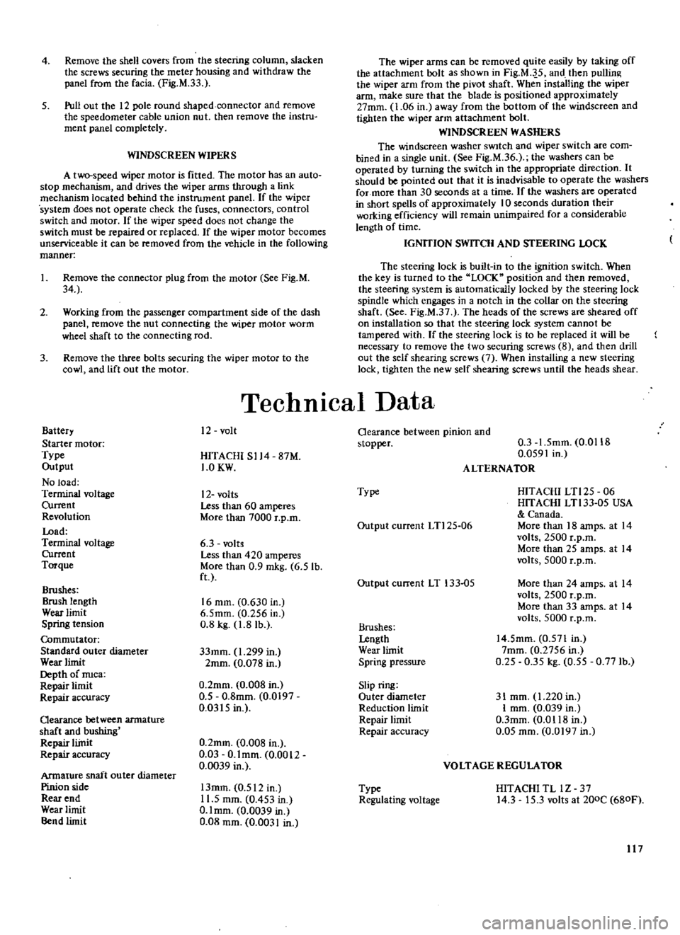
Battery
Starter
motor
Type
Output
No
load
Terminal
voltage
Current
Revolution
Load
Terminal
voltage
Current
Torque
Brushes
Brush
length
Wear
limit
Spring
tension
Commutator
Standard
outer
diameter
Wear
limit
Depth
of
nuca
Repair
limit
Repair
accuracy
Qearance
between
armature
shaft
and
bushing
Repair
liinit
Repair
accuracy
Armature
shaft
ou
ter
diameter
Pinion
side
Rear
end
Wear
limit
Bend
limit
The
wiper
arms
can
be
removed
quite
easily
by
taking
off
the
attachment
bolt
as
shown
in
Fig
M
J
5
and
then
pullin
the
wiper
arm
from
the
pivot
shaft
When
installing
the
wiper
arm
make
sure
that
the
blade
is
positioned
approximately
27mm
1
06
in
away
from
the
bottom
of
the
windscreen
and
tighten
the
wiper
arm
attachment
bolt
WINDSCREEN
WASHERS
The
windscreen
washer
SWItch
and
wiper
switch
are
com
bined
in
a
single
unit
See
Fig
M
36
the
washers
can
be
operated
by
turning
the
switch
in
the
appropriate
direction
It
should
be
pointed
out
that
it
is
inadvisable
to
operate
the
washers
for
more
than
30
seconds
at
a
time
If
the
washers
are
operated
in
short
spells
of
approximately
10
seconds
duration
their
working
efficiency
will
remain
unimpaired
for
a
considerable
length
of
time
IGNITION
SWITCH
AND
STEERING
LOCK
The
steering
lock
is
built
in
to
the
goition
switch
When
the
key
is
turned
to
the
LOCK
position
and
then
removed
the
steering
system
is
automatically
locked
by
the
steering
lock
spindle
which
engages
in
a
notch
in
the
collar
on
the
steering
shaft
See
Fig
M
37
The
heads
of
the
screws
are
sheared
off
on
installation
so
that
the
steering
lock
system
cannot
be
tampered
with
If
the
steering
lock
is
to
be
replaced
it
will
be
necessary
to
remove
the
two
securing
screws
8
and
then
drill
out
the
self
shearing
screws
7
When
installing
a
new
steering
lock
tighten
the
new
self
shearing
screws
until
the
heads
shear
TechnICal
Data
12
volt
HITACHI
S114
87M
1
0KW
12
volts
Less
than
60
amperes
More
than
7000
r
p
m
6
3
volts
Less
than
420
amperes
More
than
0
9
mkg
6
5
lb
ft
16
mm
0
630
in
6
5mm
0
256
in
0
8
kg
1
8
lb
33mm
1
299
in
2mm
0
078
in
0
2mm
0
008
in
0
5
0
8mm
0
0197
0
0315
in
0
2mm
0
008
in
0
03
O
lmm
0
0012
0
0039
in
13mm
0
512
in
11
5
mm
0
453
in
O
lmm
0
0039
in
0
08
mm
0
0031
in
Oearance
between
pinion
and
stopper
0
3
1
5mm
0
0118
0
0591
in
ALTERNATOR
Type
HITACHI
LTl25
06
HITACHI
LTl33
05
USA
Canada
More
than
18
amps
at
14
volts
2500
r
p
m
More
than
25
amps
at
14
volts
5000
r
p
m
Output
current
LTl25
06
Output
current
LT
133
05
More
than
24
amps
at
14
volts
2500
r
p
m
More
than
33
amps
at
14
volts
5000
r
p
m
Brushes
Lengtb
Wear
limit
Spring
pressure
14
5mm
0
571
In
7mm
0
2756
in
0
25
0
35
kg
0
55
0
771b
Slip
ring
Outer
diameter
Reduction
limit
Repair
limit
Repair
accuracy
31
mm
1
220
in
I
mm
0
039
in
O
3mm
0
0118
in
0
05
mm
0
0197
in
VOLTAGE
REGULATOR
Type
Regulating
voltage
HITACHI
TL
lZ
37
14
3
15
3
volts
at
200C
680F
117
Page 168 of 171

MO
MI
1224
D
I
KM
f
fMn
n
r
A
A
JP
I
I
T
I
I
I
Drain
ill
Changeelemenl
I
42
Cleantlement
3
I
II
r
I
Check
il
topup
4
I
Chinnloil
511
1
11
41
Gle
nelern
n
Ii
I
Orainlluid
7
I
I
I
I
Clunertmtn
81
1
I
I
I
I
I
27
Check
ailltop
up
Jf71
r
I
JIO
WI
28
Change
il
I
ill
limittdSlip
DiHlranti
1
Clleck
ilftopup
1J
I
I
I
Changelil
11
i
ill
ShdmgJolntt
Df
YlShlft
Check
11IIOpup
n
II
I
I
ChangeDl1
1
I
I
I
I
SHOCKASSORBERS
Check
Il
topup
5
PROP
DRIVESHAFTISI
lubncate
Hi
1
GREASE
GUN
POINTS
lubnCIl
it
PEOAlSHAFT
Sj
Lubrlc
te
18
HANDBHAKE
lubnc
1t
I
I
r
1
t
R
IINKAl
iF
luhncll
2u
I
I
i
I
ARlUWIORED
WHEELS
FREE
1m
I
I
i
1121
wHEE
L
tll
AHINli
ronl
HepitCk
211
t
f
WHEEl
BEARINGS
Rur
Repack
77
U
I
BRAKE
FLUID
R
nfWfbletd
1
I
lf
13
117
I
t
I
AH
UUWI
f
t1UN
11Itl
ih1tl
1
i
lcl
Check
oillevtl
B
l
r1i
BI1I1I1
r
Cap
Cleen
1ifj
j
I
Air
Cluner
Service
el
m
nt
l
J7
4
Replace
element
l
l
B
L
5
Cteenfilter
1
C
l
I
I
I
4
Clun
va
vellllR
I
I1
I
I
I
Repl
cH
lve
1
I
I
I
I
Cleen
jets
bOM
R
t
I
Top
liP
pisl
dempe
l
I
r
L
LlIbncatelinkages
I
I
L
Ctean
replace
5
j
I
Ch
ckoill
ve1
Ei
l
j
16
Clun
replac
n
11
R
fill
witll
fluid
38
I
Check
fluid
levll
IlL
t
I
CI
ign
toil
t
i
I
t
1
l
9
CheCk
top
u
p
10
Flulhryst
m
y
Cllecksolullon
44
Chltk
45
Lubrlc
tt
46
i
Clleck
top
up
L
L
Check
topup
4
aJdM
Cllltkspet
gl1vity
i
CI
en
gr
1S
liD
116
Lubriclt
1il
If
I
II
Clleck
topup
52
1
i
Chtck
topuplluid
3
I
I
Gre
rlm
4
I
1
I
I
I
Clunfiltlr
55
L
I
I
I
Chick
top
up
fluid
I6
w
W
e
I
ofi
Ldtir
1
Renewfiltlr
58
I
Check
topupflu
d
i91
i
I
i
Renrwfluid
I
I
I
I
I
ilinlil1r
11
I
I
I
I
I
I
CAR
DOWN
E
TERNAL
j
II
1
I
1
lOCKS
HINGES
Ell
Lubrictt
S21
r
1
el
L
Door
Dram
Hol
l
Clun
f
J
I
I
WIPER
SPINDLES
lubrictt
64
W
I
I
En
in
Dil
Filwr
GttrbOK
1968
Lubricate
and
Clean
ENGINE
Filt
r
GEARBOX
Dvttdrivt
Filt
r
AUTOMATIC
TRANSM
Filt
r
DIFFERENTIAL
PCV
Syllem
rburettor
s
FUll
Bowl
Filter
S1
Fu
llnjectionPump
Fittll
ll
AUTOMATIC
TRANSM
DISTRIBUTOR
Spindl
Ctm
COOLING
SYSTEM
CorrDlionlnllibitor
Anti
Frltl
W
t
rPump
CREENWASHER
ArrERY
Connections
3ENERATOR
STEERING
POMrStlering
CLUTCH
BRAKE
BRAKE
SERVO
HYDR
SUSPENSION
CAPACITIES
LUBRICANTS
Il
D
P
LUSClu
Service
Check
Adjust
CAR
UP
I
l
lletksumpbulttortM
1
Clled
rque
i6
ServiceJndclean
J1
Adjult
brake
bandl
tB
RtnMsumpgal
tt
fiS
Check
llJmpbnlttort
PROP
lOAIVE
SHAFT
S
Check
lor
wear
JJ
Tiglltenbolu
Jl
Check
tor
wear
n
Tiglltenboltl
Clllckbootgeiltrl
Clleckoperltion
Ch
CQmpon
l
welr
Tighten
bolts
Clleclbootgaiterl
Checktorqu
Gheck
edjult
Clllck
ljust
CIIRCk
adjult
Clleck
tighltnbolts
W
M
KSI
1
t
heCklMliiili
86
Check
ldjust
81
Overllllulcompl
rvll
Cleen
chltkwtlr
R9
Check
for
wear
0
Check
9
Checkforwp
lr
192
Il1Ipecttyrel
1IJ
Illte
II
blIl1nCl
Adjultpres
lure
Cllecktorul
liON
ET
OPE
l
heckcompression
Checktorqul
AdjUltclttr
nc
CheckoptTltion
Check
lIljLllt
AdjUlI
Clleck
alIj
tension
adj
t
nsion
I
Clun
selpp
jt1
Renew
Chetk
tPoint
tp
Renew
pointl
Check
6djult
110
J
Check
edjult
ill
i
ii
j
Tiglltenhoseclips
112
R
plece
lIastl
ill
PreSSIJ
test
114
1
STEERING
Clleek
play
adjust
ill
j
i
itl
e
Ti9htenboltl
ill
ii
Geometry
Check
U1L
H
CHECK
FOR
Oil
FUEL
WATER
etc
LEAKS
1181
I
I
R
DOWN
FXIE
HNA
11
1
1
lIGHTS
If
isfHUMt
NTS
Check
flll
C
lOn
f
3
Headlights
Checkllhgnmlnt
112Cr
WIPERS
Checkbladu
11111
J
TS
r
h
kIl
CII
I
Jrl7
iI
An
UH
OVNAUOMFTER
I
ST
I
BRAKES
CheCkemCienCY
1
I
AUTOMATIC
TRANSM
Clleek
op
rttioQ
T
ENGINE
Adjust
if
required
12
DEFECTS
Report
12
EVERY
MOnthl
Miles
1000
KMs
1000
lIBt
wtJichewl
ENGINE
EngmlMountings
Engine
Film
Trap
AUTOMATIC
TRANSM
24
2
30
SUSP
FRONT
REAR
Shock
Ablorb
rs
STEERING
1
21
5
1
c
e
U
80lTS
HANDBRAKE
CLUTCH
GEAR
LINKAGE
EXHAUST
SYSTEM
f
HFf
K
FOR
Oil
FllE
1
CAH
LUWI
RI
If
WHEEL
BEARINGS
BRAKES
UningsJDruml
Plds
Discl
Selhdj
Meclleni5l11
Cylinders
Hosel
ROAD
WHEELS
3S
Whe
1
Nun
AHllIIWN
ENGINE
Cyllnd
r
Held
Vllyes
Clloke
MiKtulli
ldling
linkagel
Timing
Ch
in
16
V
Belt
Is
SPARK
PLUGS
OISTRIBUTOR
Owell
Angle
Ignition
Timing
COOLING
SYSTEM
8
X
Automatic
Diffrrrntill
ICoolinginc
Ht
lltel
AntilrH1f
Ltr
lmoP
Ugo
IL
dmo
PII
U
Ou
HydrJBrak
Fluid
4
7
1
21
81
7
ULlma
II
USP
ULlmD
USP
L
L
tmoP
USQu
127
2
4
4
SAE
3O
2OW
411
SAE
lfrN
2fJ
IOWI3O
SAE1OW
IOW
30
320C
JOe
o
e
SAE80
EP
SAE90EP
SAE
140
EP
mmDIIIII
Ifn
c
ID
WIthDv
1
LI
obWt7
3
LtrJ
PtLUSPtL
3
2
0
75
T
3
1
8
B
8
WAGON
1
1
72
1
TYPE
A
SUFFIX
A
SAE80
EP
SAE90EP
SAE
140EP
0
aSoC
BFl
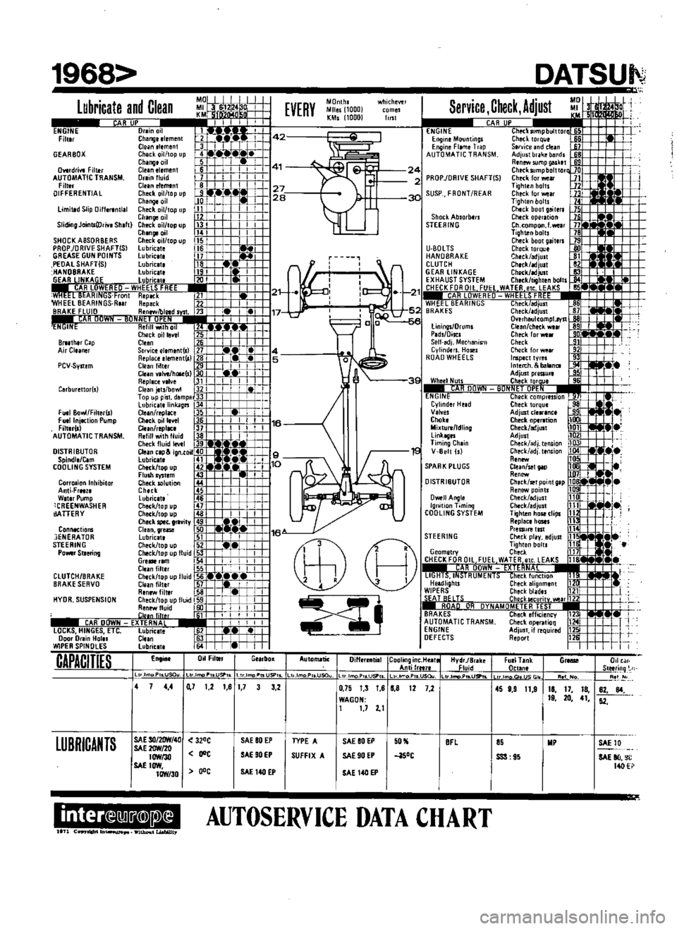
AUTOSERVICE
DATA
CHART
DATSUI
D
FurlT
nk
n
tln
G
0
Slltring
Re
I
lm
r
JSGI
11
1
No
4S
8
9
11
9
11
17
18
19
20
41
82
84
52
SSS
95
SAElll
SAE
80
c
14O