check engine DATSUN B110 1973 Service User Guide
[x] Cancel search | Manufacturer: DATSUN, Model Year: 1973, Model line: B110, Model: DATSUN B110 1973Pages: 513, PDF Size: 28.74 MB
Page 62 of 513
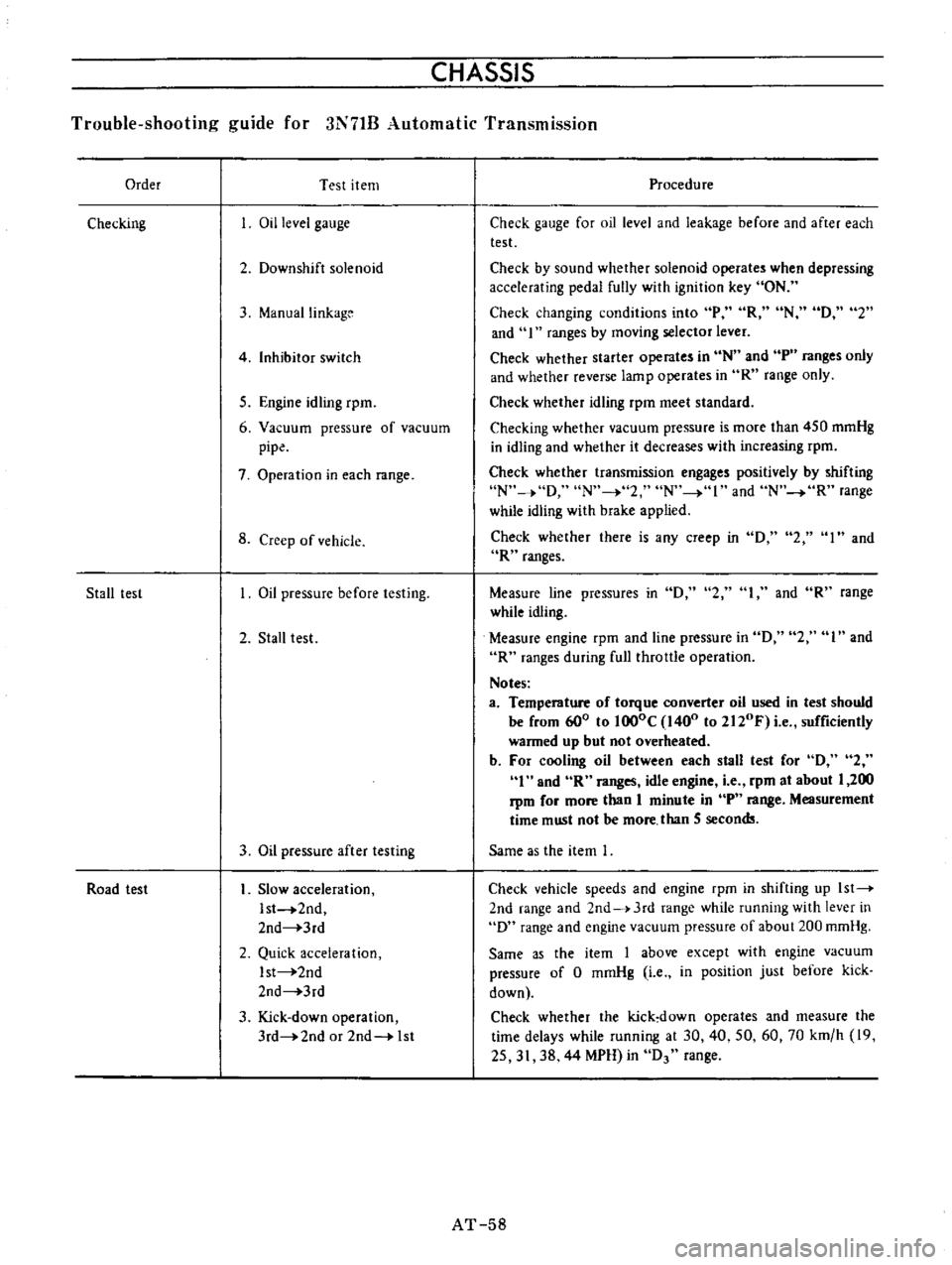
CHASSIS
Trouble
shooting
guide
for
3N71B
Automatic
Transmission
Order
Test
item
Checking
Oil
level
gauge
2
Downshift
solenoid
3
ManuaIlinkage
4
Inhibitor
switch
5
Engine
idling
rpm
6
Vacuum
pressure
of
vacuum
pipe
7
Operation
in
each
range
8
Creep
of
vehicle
Stall
lest
Oil
pressure
before
testing
2
Stall
test
3
Oil
pressure
after
testing
Road
test
Slow
acceleration
Ist
2nd
2nd
3rd
2
Quick
acceleration
Ist
2nd
2nd
3rd
3
Kick
down
operation
3rd
2nd
or
2nd
1st
Procedure
Check
gauge
for
oil
level
and
leakage
before
and
after
each
test
Check
by
sound
whether
solenoid
operates
when
depressing
accelerating
pedal
fully
with
ignition
key
ON
Check
changing
conditions
into
P
R
N
D
2
and
I
ranges
by
moving
selector
lever
Check
whether
starter
operates
in
N
and
tp
ranges
only
and
whether
reverse
lamp
operates
in
R
range
only
Check
whether
idling
rpm
meet
standard
Checking
whether
vacuum
pressure
is
more
than
450
mmHg
in
idling
and
whether
it
decreases
with
increasing
rpm
Check
whether
transmission
engages
positively
by
shifting
N
o
D
N
2
N
I
and
N
R
range
while
idling
with
brake
applied
Check
whether
there
is
any
creep
in
D
2
I
and
R
ranges
2
1
and
R
range
Measure
line
pressures
in
D
while
idling
Measure
engine
rpm
and
line
pressure
in
D
2
I
and
R
ranges
during
fullthrallIe
operation
Notes
a
Temperature
of
torque
converter
oil
used
in
test
should
be
from
600
to
lOOoC
1400
to
2120F
i
e
sufficiently
warmed
up
but
not
overheated
b
For
cooling
oil
between
each
stall
test
for
D
2
1
and
R
ranges
idle
engine
i
e
rpm
at
about
1
200
rpm
for
more
than
1
minute
in
P
range
Measurement
time
must
not
be
more
than
5
secon
Same
as
the
item
I
Check
vehicle
speeds
and
engine
rpm
in
shifting
up
1st
2nd
range
and
2nd
J
3rd
range
while
running
with
lever
in
D
range
and
engine
vacuum
pressure
of
about
200
mmHg
Same
as
the
item
1
above
except
with
engine
vacuum
pressure
of
0
mmHg
i
e
in
position
just
before
kick
down
Check
whether
the
kick
down
operates
and
measure
the
time
delays
while
running
at
30
40
50
60
70
km
h
19
25
31
38
44
MPH
in
D
range
AT
58
Page 63 of 513
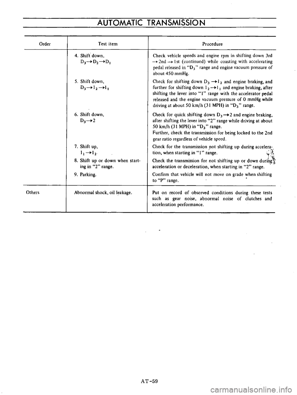
Order
Others
AUTOMATIC
TRANSMISSION
Test
item
4
Shift
down
Dr4D2
DI
5
Shift
down
DJ
I2
l
6
Shift
down
DJ
2
7
Shift
up
I
12
8
Shift
up
or
down
when
start
ing
in
2
range
9
Parking
Abnormal
shock
oil
leakage
Procedure
Check
vehicle
speeds
and
engine
rpm
in
shifting
down
3rd
2nd
I
st
continued
while
coasting
with
acceleraling
pedal
released
in
0
range
and
engine
vacuum
pressure
of
about
450
mmHg
Check
for
shifting
down
DJ
12
and
engine
braking
and
further
for
shifting
down
12
11
and
engine
braking
after
shifting
the
lever
into
I
range
with
the
accelerator
pedal
released
and
the
engine
vacuum
pressure
of
0
mmHg
while
driving
at
about
SO
km
h
31
MPH
in
DJ
range
Check
for
quick
shifting
down
DJ
2
and
engine
braking
after
shifting
the
lever
into
2
range
while
driving
at
about
50
km
h
31
MPH
in
DJ
range
Further
check
the
transmission
for
being
locked
to
the
2nd
gear
ratio
regardless
of
vehicle
speed
Check
for
the
transmission
not
shifting
up
during
acceIera
tion
when
starting
in
1
t
nge
It
Check
the
transmission
for
not
shifting
up
or
down
durih
t
acceleration
or
deceleration
when
starting
in
2
range
Confirm
that
vehicle
will
not
move
on
grade
when
shifting
to
P
range
Put
on
record
of
observed
conditions
during
these
tests
such
as
gear
noise
abnormal
noise
of
clutches
and
acceleration
performance
AT
59
Page 131 of 513
Tightening
torque
3
way
connector
1
5
to
1
8
kg
m
10
8
to
13
0
ft
lh
1
5
to
1
8
kg
m
10
8
to
13
0
ft
lh
1
5
to
1
8
kg
m
10
8
to
13
0
ft
lb
0
7
to
0
9
kg
m
5
1
to
6
5
ft
1b
Master
cylinder
Brake
hose
Air
bleeder
5
Fill
the
master
cylinder
brake
fluid
reservoir
with
brake
fluid
and
perform
air
bleeding
complele1y
Note
a
Do
not
use
brake
fluid
other
than
specified
b
The
specified
brake
fluid
is
used
for
both
single
and
tandem
type
master
cylinders
6
Upon
completion
of
air
bleeding
make
sure
that
the
brake
operates
correctly
and
check
the
brake
tube
and
hose
connectors
for
fluid
leaking
Fully
depress
the
brake
pedal
continue
to
depress
the
brake
pedal
for
several
seconds
and
make
sure
that
no
brake
fluid
leaks
from
any
part
of
the
brake
line
Replace
defective
part
if
required
Brake
line
pressure
differential
warning
light
switch
A
warning
light
is
located
on
the
instrument
panel
to
warn
the
driver
when
a
pressure
difference
of
13
to
17
kg
cm2
185
to
2421bJsq
in
exists
between
the
front
and
rear
b
rake
systems
A
hydraulically
actuated
warning
light
switch
is
located
in
the
engine
compartment
Both
front
and
rear
brake
systems
are
connected
to
this
switch
assembly
When
a
pressure
difference
of
13
to
17
kgJcm2
185
to
242
lbJsq
in
occurs
between
the
front
and
rear
brake
systems
the
valves
will
shuttle
toward
the
side
with
the
low
pressure
The
valve
contacts
with
the
switch
terminal
BRAKE
the
ground
circuit
for
the
warning
light
is
completed
and
thus
the
warning
light
lights
In
this
case
correct
the
hydraulic
brake
problem
and
bleed
the
brakes
Check
the
warning
light
switch
assembly
for
a
proper
operation
Check
the
switch
assembly
for
fluid
leakage
Note
Do
not
attempt
to
repair
switch
for
any
reason
replace
switch
assembly
completely
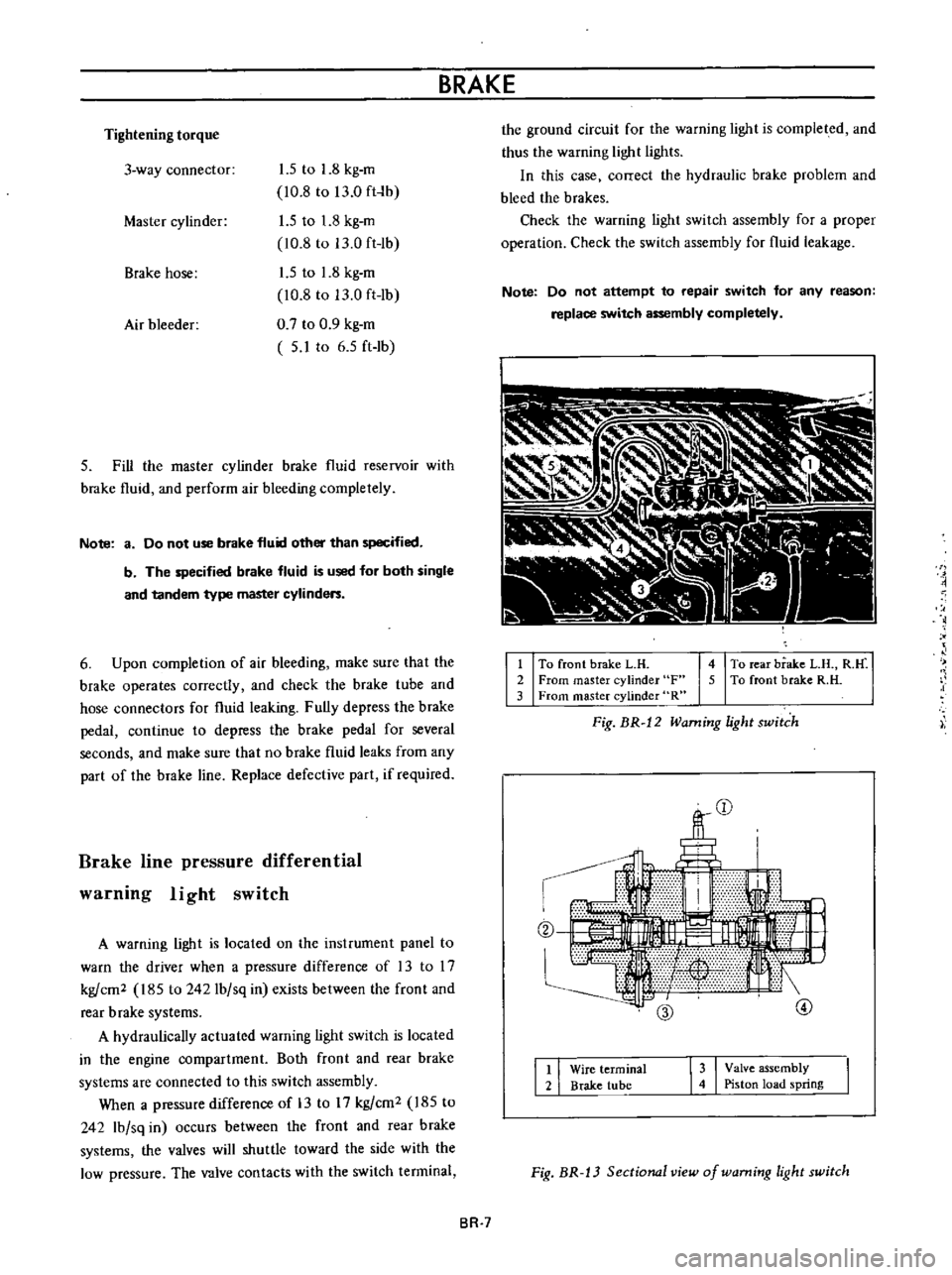
1
To
front
brake
L
H
2
From
master
cylinder
F
3
From
master
cylinder
R
4
To
rear
brake
L
B
R
M
5
To
front
brake
R
H
Fig
BR
12
Warning
light
switch
r
I
@
I
I
3
I
Valve
assembly
4
Piston
load
spring
Wire
terminal
Brake
tube
Fig
BR
13
Sectional
view
of
warning
light
switch
BR
7
Page 225 of 513
BODY
b
Method
2
Start
the
engine
and
turn
on
the
window
defogger
system
With
a
d
c
voltmeter
setup
shown
in
Figure
BF
70
check
each
heat
wire
for
discontinuity
If
the
meter
indicates
12
volts
or
0
on
a
specific
wire
that
line
is
broken
Normal
indication
6
volts
A
break
in
that
line
can
then
be
detected
by
moving
the
positive
lead
of
meter
along
the
line
until
an
abrupt
variation
in
the
meter
indication
is
encountered
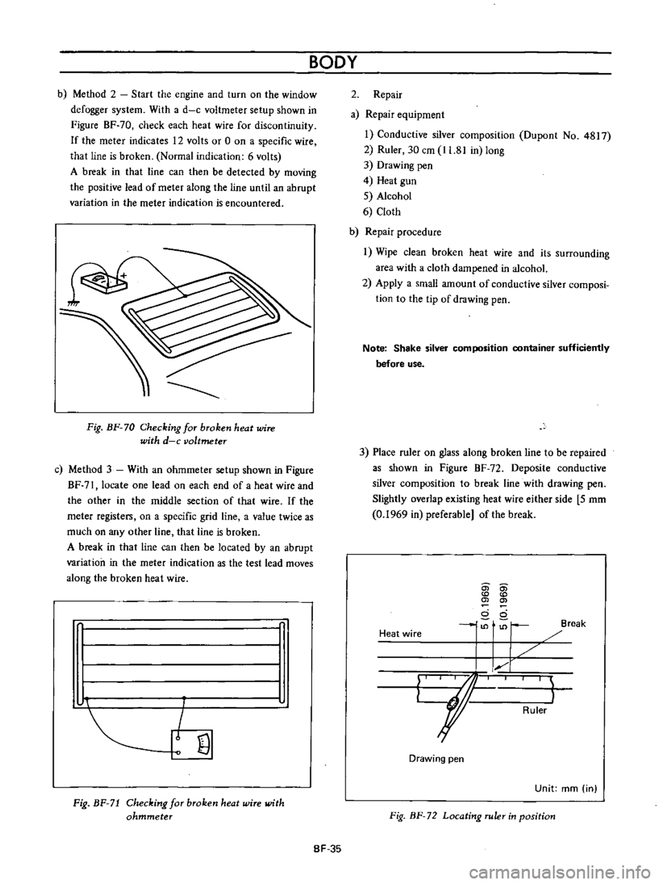
Fig
BF
70
Checking
for
broken
heat
wire
with
d
c
voltmeter
c
Method
3
With
an
ohmmeter
setup
shown
in
Figure
BF
7l
locate
one
lead
on
each
end
of
a
heat
wire
and
the
other
in
the
rniddle
section
of
that
wire
If
the
meter
registers
on
a
specific
grid
line
a
value
twice
as
much
on
any
other
line
that
line
is
broken
A
break
in
that
line
can
then
be
located
by
an
abrupt
variation
in
the
meter
indication
as
the
test
lead
moves
along
the
broken
heat
wire
r
I
I
I
J
I
I
v
Ejl
Fig
BF
71
Checking
for
broken
heat
wire
with
ohmmeter
2
Repair
a
Repair
equipment
1
Conductive
silver
composition
Dupont
No
4817
2
Ruler
30
em
11
81
in
long
3
Drawing
pen
4
Heat
gun
5
Alcohol
6
Cloth
b
Repair
procedure
1
Wipe
clean
broken
heat
wire
and
its
surrounding
area
with
a
cloth
dampened
in
alcohol
2
Apply
a
small
amount
of
conductive
silver
composi
tion
to
the
tip
of
drawing
pen
Note
Shake
silver
composition
container
sufficiently
before
use
3
Place
ruler
on
glass
along
broken
line
to
be
repaired
as
shown
in
Figure
BF
72
Deposite
conductive
silver
composition
to
break
line
with
drawing
pen
Slightly
overlap
existing
heat
wire
either
side
5
mm
0
1969
in
preferable
of
the
break
Heat
wire
0
en
0
0
d
ci
1
I
Break
I
1
I
kr
I
I
Ruler
Drawing
pen
Unit
mm
in
Fig
BF
72
Locating
ruler
in
position
8F
35
Page 241 of 513
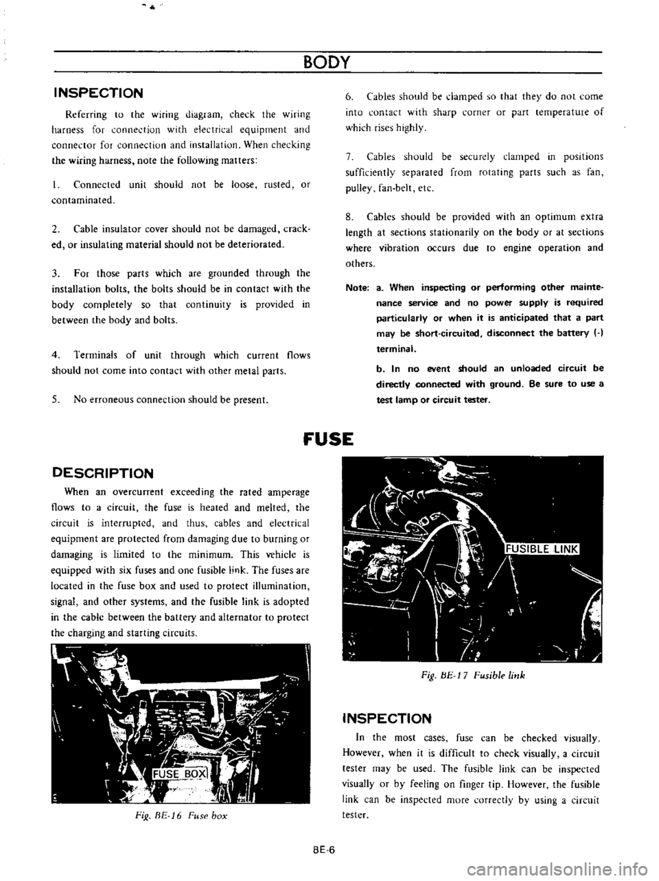
INSPECTION
Referring
to
the
wiring
diagram
check
the
wiring
harness
for
connection
with
electrical
equipment
and
connector
for
conned
ion
and
installation
When
checking
the
wiring
harness
note
the
following
matters
Connected
unit
should
not
be
loose
rusted
or
contaminated
2
Cable
insulator
cover
should
not
be
damaged
crack
ed
or
insulating
material
should
not
be
deteriorated
3
For
those
parts
which
are
grounded
through
the
installation
bolts
the
bolts
should
be
in
contact
with
the
body
completely
so
that
continuity
is
provided
in
between
the
body
and
bolts
4
Terminals
of
unit
through
which
current
flows
should
not
come
into
contact
with
other
metal
parts
5
No
erroneous
connection
should
be
present
DESCRIPTION
When
an
overcunent
exceeding
the
rated
amperage
flows
to
a
circuit
the
fuse
is
heated
and
melted
the
circuit
is
interrupted
and
thus
cables
and
electrical
equipment
are
protected
from
damaging
due
to
burning
or
damaging
is
limited
to
the
minimum
This
vehicle
is
equipped
with
six
fuses
and
one
fusible
link
The
fuses
are
located
in
the
fuse
box
and
used
to
protect
illumination
signal
and
other
systems
and
the
fusible
link
is
adopted
in
the
cable
between
the
battery
and
alternator
to
protect
the
charging
and
starting
circuits
FiJ
BE
16
Fuse
box
BODY
6
Cables
should
be
damped
so
that
they
do
not
come
into
contact
with
sharp
corner
or
part
lernperature
of
which
rises
highly
7
Cables
should
be
securely
clamped
in
posItions
sufficiently
separated
from
rotating
parts
such
as
fan
pulley
fan
belt
etc
8
Cables
should
be
provided
with
an
optimum
extra
length
at
sections
stationarity
on
the
body
or
at
sections
where
vibration
occurs
due
to
engine
operation
and
others
Note
a
When
inspecting
or
performing
other
mainte
nance
service
and
no
power
supply
is
required
particularly
or
when
it
is
anticipated
that
a
part
may
be
short
circuited
disconnect
the
battery
H
terminal
b
In
no
event
should
an
unloaded
circuit
be
directly
connected
with
ground
Be
sure
to
use
a
test
lamp
or
circuit
tester
fUSE
Fig
BE
17
Fusible
link
INSPECTION
In
the
most
cases
fuse
can
be
checked
visually
However
when
it
is
difficult
to
check
visually
a
circuit
tester
may
be
used
The
fusible
link
can
be
inspected
visually
or
by
feeling
on
finger
tip
However
the
fusible
link
can
be
inspected
more
correctly
by
using
a
circuit
tester
BE
6
Page 248 of 513
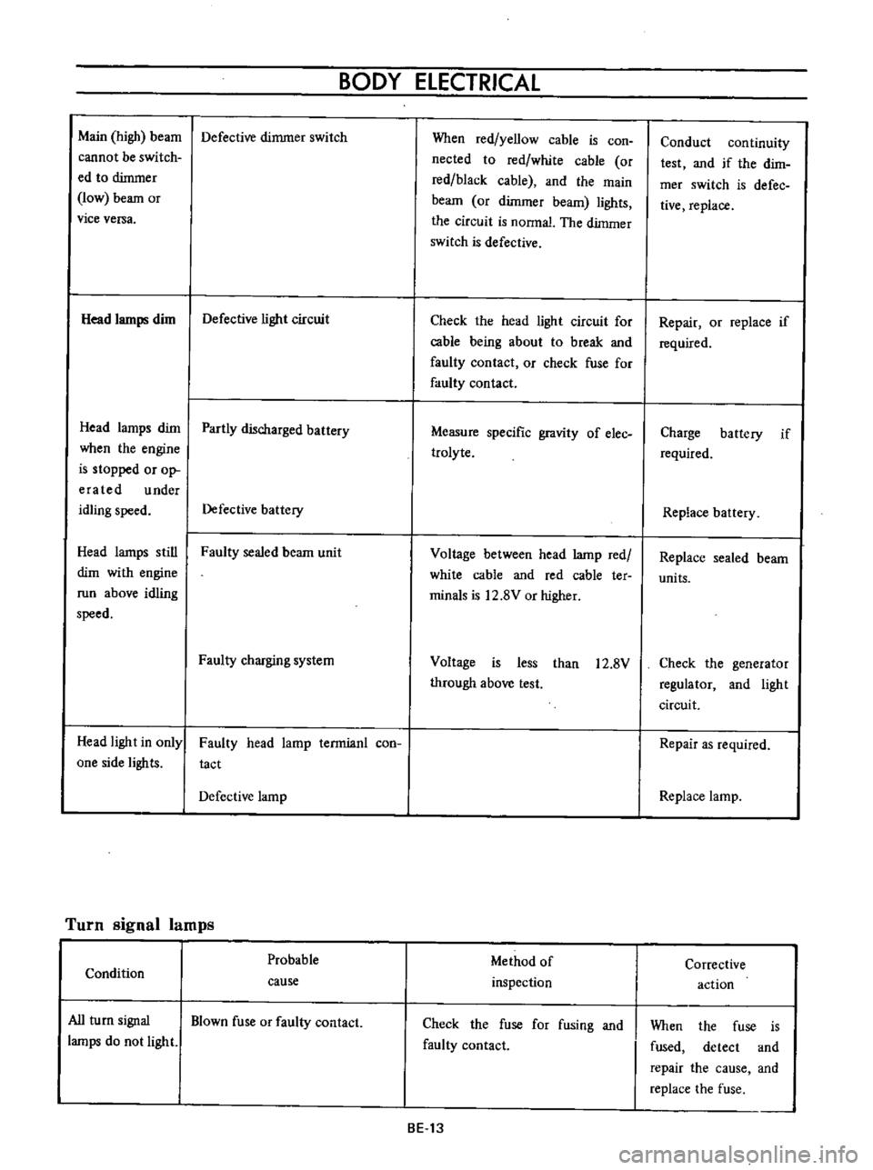
BODY
ELECTRICAL
Main
high
beam
Defective
dimmer
switch
cannot
be
switch
ed
to
dimmer
low
beam
or
vice
versa
Head
lamps
dim
Defective
light
circuit
Head
lamps
dim
Partly
discharged
battery
when
the
engine
is
stopped
or
op
era
ted
under
idling
speed
Defective
battery
Head
lamps
still
Faulty
sealed
beam
unit
dim
with
engine
run
above
idling
speed
Faulty
charging
system
Head
light
in
only
one
side
lights
Faulty
head
lamp
terrnianl
con
tact
Defective
lamp
Turn
signal
lamps
Probable
Condition
cause
All
turn
signal
Blown
fuse
or
faulty
contact
lamps
do
not
light
When
red
yellow
cable
is
con
nected
to
red
white
cable
or
red
black
cable
and
the
main
beam
or
dimmer
beam
lights
the
circuit
is
nonnal
The
dimmer
switch
is
defective
Check
the
head
light
circuit
for
cable
being
about
to
break
and
faulty
contact
or
check
fuse
for
faulty
contact
Measure
specific
gravity
of
elec
trolyte
Voltage
between
head
lamp
red
white
cable
and
red
cable
ter
minals
is
12
8V
or
higher
Voltage
is
less
than
12
8V
through
above
test
Method
of
inspection
Check
the
fuse
for
fusing
and
faulty
contact
BE
13
Conduct
continuity
test
and
if
the
dirn
mer
switch
is
defec
tive
replace
Repair
or
replace
if
required
Charge
battery
if
required
Replace
battery
Replace
sealed
beam
units
Check
the
generator
regulator
and
light
circuit
Repair
as
required
Replace
lamp
Corrective
action
When
the
fuse
is
fused
detect
and
repair
the
cause
and
replace
the
fuse
Page 260 of 513
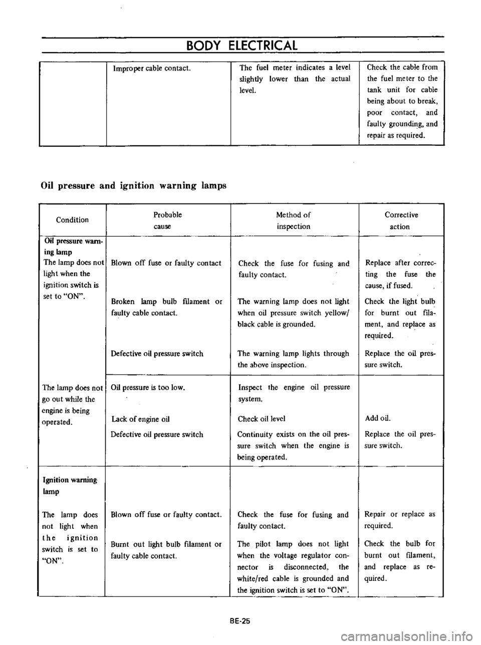
BODY
ELECTRICAL
Improper
cable
contact
Oil
pressure
and
ignition
warning
lamps
Condition
Oil
pressure
Want
ing
lamp
The
lamp
does
not
ligh
t
when
the
ignition
switch
is
set
to
ON
Probable
cause
Blown
off
fuse
or
faulty
contact
Broken
lamp
bulb
fIlarnent
or
faulty
cable
contact
Defective
oil
pressure
switch
The
lamp
does
not
Oil
pressure
is
too
low
go
out
while
the
engine
is
being
operated
Lack
of
engine
oil
Defective
oil
pressure
switch
Ignition
warning
lamp
The
lamp
does
not
light
when
the
ignition
switch
is
set
to
ON
Blown
off
fuse
or
faulty
contact
Burnt
out
light
bulb
filarnent
or
faulty
cable
contact
The
fuel
rneter
indicates
a
level
slightly
lower
than
the
actual
level
Method
of
inspection
Check
the
fuse
for
fusing
and
faulty
contact
The
warning
lamp
does
not
light
when
oil
pressure
switch
yellow
black
cable
is
grounded
The
warning
lamp
lights
through
the
above
inspection
Inspect
the
engine
oil
pressure
system
Check
oil
level
Continuity
exists
on
the
oil
pres
sure
switch
when
the
engine
is
being
operated
Check
the
fuse
for
fusing
and
faulty
contact
The
pilot
lamp
does
not
light
when
the
voltage
regulator
con
nector
is
disconnected
the
white
red
cable
is
grounded
and
the
ignition
switch
is
set
to
ON
BE
25
Check
the
cable
from
the
fuel
meter
to
the
tank
unit
for
cable
being
about
to
break
poor
contact
and
faulty
grounding
and
repair
as
required
Corrective
action
Replace
after
corree
ting
the
fuse
the
cause
if
fused
Check
the
light
bulb
for
burnt
out
fIla
ment
and
replace
as
required
Replace
the
oil
pres
sure
switch
Add
oil
Replace
the
oil
pres
sure
switch
Repair
or
replace
as
required
Check
the
bulb
for
burnt
out
fIlament
and
replace
as
re
quired
Page 268 of 513
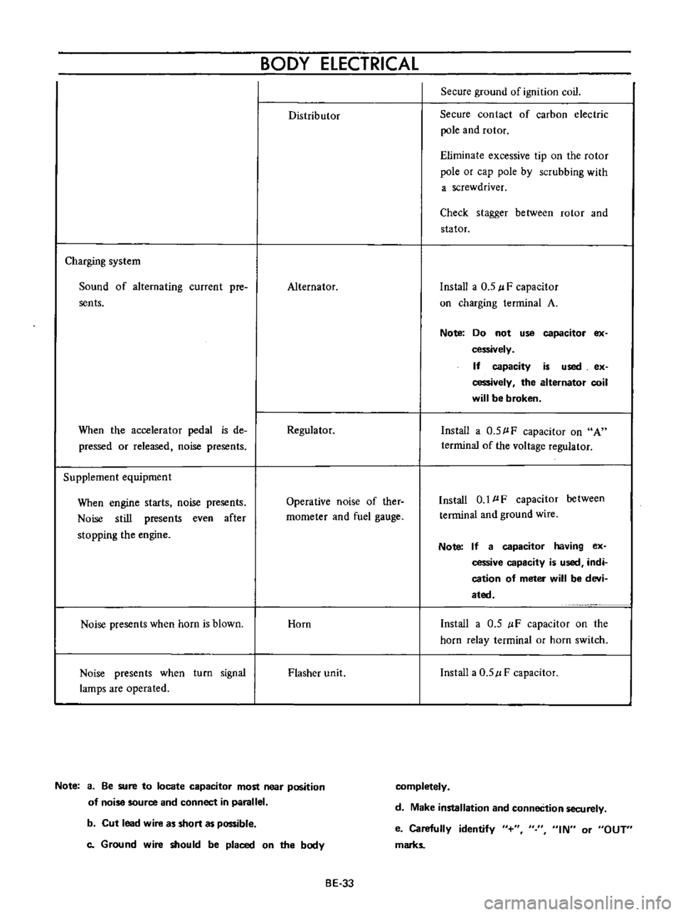
BODY
ELECTRICAL
Distributor
Secure
ground
of
ignition
coil
Secure
contact
of
carbon
electric
pole
and
rotor
Eliminate
excessive
tip
on
the
rotor
pole
or
cap
pole
by
scrubbing
with
a
screwdriver
Check
stagger
between
rotor
and
stator
Charging
system
Sound
of
alternating
current
pre
sents
Alternator
Install
a
0
5
l
F
capacitor
on
charging
terminal
A
Note
Do
not
use
capacitor
ex
cessively
If
capacity
is
used
ex
cessively
the
alternator
coil
will
be
broken
When
the
accelerator
pedal
is
de
pressed
or
released
noise
presents
Regulator
Install
a
0
5
l
F
capacitor
on
A
terrninal
of
the
voltage
regulator
Supplement
equipment
When
engine
starts
noise
presents
Noise
still
presents
even
after
stopping
the
engine
Operative
noise
of
ther
rnometer
and
fuel
gauge
Install
0
1
l
F
capacitor
between
terminal
and
ground
wire
Note
If
a
capacitor
having
ex
cessive
capacity
is
used
indi
cation
of
meter
will
be
devi
ated
Noise
presents
when
horn
is
blown
Horn
Install
a
0
5
IF
capacitor
on
the
horn
relay
terminal
or
horn
switch
Noise
presents
when
turn
signal
lamps
are
operated
Flasher
unit
Install
a
0
5
l
F
capacitor
Note
a
Be
sure
to
locate
capacitor
most
near
position
of
noise
source
and
connect
in
parallel
completely
d
Make
installation
and
conneCtion
securely
b
Cut
lead
wire
as
short
as
possible
c
Ground
wire
should
be
placed
on
the
body
e
Carefully
identify
marks
IN
or
OUT
BE
33
Page 306 of 513
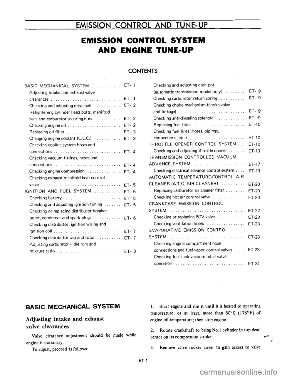
EMISSION
CONTROL
AND
TUNE
UP
EMISSION
CONTROL
SYSTEM
AN
D
ENGINE
TUNE
UP
CONTENTS
BASIC
MECHANICAL
SYSTEM
ET
Checking
and
adjusting
dash
pot
Adjusting
intake
and
exhaust
valve
automatic
transmission
model
only
ET
9
clearances
ET
1
Checking
carburetor
return
spring
ET
9
Checking
and
adjustin9
drive
belt
ET
2
Checking
choke
mechanism
choke
valve
Retightening
cylinder
head
bolts
manifold
and
linkagel
ET
9
nuts
and
carburetor
securing
nuts
ET
2
Checking
anti
dieseling
solenoid
ET
9
Checking
engine
oil
ET
2
Replacing
fuel
filter
ET
10
Replacing
oil
filter
ET
3
Checking
fuel
lines
hoses
pipings
Changing
engine
coolant
L
L
C
ET
3
connections
etc
ET10
Checking
cooling
system
hoses
and
THROTTLE
OPENER
CONTROL
SYSTEM
ET
10
connections
ET
4
Checking
and
adjusting
throttle
opener
ET
13
Checking
vacuum
fittings
hoses
and
TRANSMISSION
CONTROLLED
VACUUM
connections
ET
4
ADVANCE
SYSTEM
ET
17
Checking
engine
compression
ET
4
Checking
electrical
advance
control
system
ET
19
Checking
exhaust
manifold
heat
control
AUTOMATIC
TEMPERATURE
CONTROL
AIR
valve
ET
5
CLEANER
A
T
C
AIR
CLEANER
ET
20
IGNITION
AND
FUEL
SYSTEM
ET
5
Replacing
carburetor
air
cleaner
filter
ET
20
Checking
battery
ET
5
Checking
hot
air
control
valve
ET
20
Checking
and
adjusting
ignition
timing
ET
5
CRANKCASE
EMISSION
CONTROL
Checking
or
replacing
distributor
breaker
SYSTEM
ET
22
point
condenser
and
spark
plugs
ET
6
Checking
or
replacing
PCV
valve
ET
23
Checking
distributor
ignition
wiring
and
Checking
ventilation
hoses
ET
23
ignition
coil
ET
7
EVAPORATIVE
EMISSION
CONTROL
Checking
distributor
cap
and
rotor
ET
7
SYSTEM
ET
23
Adjusting
carburetor
id
Ie
rpm
and
Checking
engine
compartment
hose
mixture
ratio
ET
8
connections
and
fuel
vapor
control
valves
ET
23
Checking
fuel
tank
vacuum
relief
valve
operation
ET
24
BASIC
MECHANICAL
SYSTEM
1
Start
engine
and
run
it
until
it
is
heated
to
operating
temperature
or
at
least
more
than
800C
I760F
of
engine
oil
temperature
then
stop
engine
Adjusting
intake
and
exhaust
valve
clearances
Valve
clearance
adjustment
should
be
made
while
engine
is
stationary
To
adjust
proceed
as
follows
2
Rotate
crankshaft
to
bring
No
1
cylinder
in
top
dead
center
on
its
compression
stroke
3
Remove
valve
rocker
cover
to
gain
access
to
valve
ET
1
Page 307 of 513
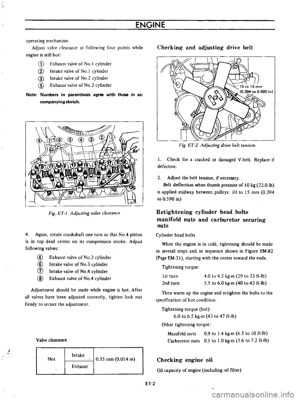
ENGINE
operating
mechanism
Adjust
valve
clearance
at
following
four
points
while
engine
is
still
hot
G
Exhaust
valve
of
No
1
cylinder
CV
Intake
valve
of
No
1
cylinder
CID
Intake
valve
of
No
2
cylinder
CID
Exhaust
valve
of
No
3
cylinder
Note
Numbers
in
parenthesis
agree
with
those
in
ac
companying
sketch
I
Fig
BY
1
Adjusting
valve
clearance
4
Again
rotate
crankshaft
one
turn
so
that
No
4
piston
is
in
top
dead
ce
lter
on
its
compression
stroke
Adjust
follnwing
valves
@
Exhaust
valve
of
No
2
cylinder
@
Intake
valve
of
No
3
cylinder
f
Intake
valve
of
No
4
cylinder
@
Exhaust
valve
of
No
4
cylinder
Adjustment
should
be
made
while
engine
is
hot
After
all
valves
have
been
adjusted
correctly
tighten
lock
nut
firmly
to
secure
the
adjustment
Vah
e
clearance
Hot
Intake
0
35
mm
0
014
in
Exhaust
Checking
and
adjusting
drive
belt
II
I
Fig
ET
2
Adjusting
drive
belt
tension
I
Check
for
a
cracked
or
damaged
V
belt
Replace
if
defective
2
Adjust
the
belt
tension
if
necessary
Belt
deflection
when
thumb
pressure
of
10
kg
22
0
lb
is
applied
midway
between
pulleys
10
to
15
mm
0
394
to
0
590
in
Retightening
cylinder
head
bolts
manifold
nuts
and
carburetor
securing
nuts
Cylinder
head
bolts
When
the
engine
is
in
cold
tightening
should
be
made
in
several
steps
and
in
sequence
shown
in
Figure
EM
82
page
EM
31
starting
with
the
center
toward
the
ends
Tightening
torque
1st
turn
2nd
turn
4
0
to
4
5
kg
m
29
to
33
ft
lb
5
5
to
6
0
kg
m
40
to
43
ft
lb
Then
warm
up
the
engine
and
retighten
the
bolts
to
the
specification
of
hot
condition
Tightening
torque
hot
6
0
to
6
5
kg
m
43
to
47
ft
lb
Other
tightening
torque
Manifold
nuts
0
9
to
14
kg
m
6
5
to
10
ft
lb
Carburetor
nuts
0
5
to
LO
kg
m
3
6
to
7
2
ft
lb
Checking
engine
oil
Oil
capacity
of
engine
including
oil
filter
ET
2