check engine DATSUN B110 1973 Service Workshop Manual
[x] Cancel search | Manufacturer: DATSUN, Model Year: 1973, Model line: B110, Model: DATSUN B110 1973Pages: 513, PDF Size: 28.74 MB
Page 359 of 513
ENGINE
MECHANICAL
Note
8
When
the
piston
ring
only
is
to
be
replaced
without
the
cylinder
bore
being
corrected
measure
gap
at
the
bottom
of
the
cylinder
where
the
wear
is
minor
b
Oversize
piston
rings
are
available
for
service
50
100
150
oversize
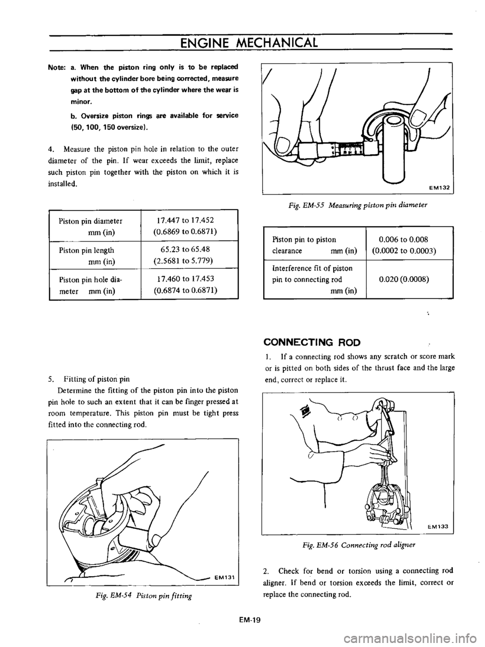
4
Measure
the
piston
pin
hole
in
relation
to
the
outer
diameter
of
the
pin
If
wear
exceeds
the
limit
replace
such
piston
pin
together
with
the
piston
on
which
it
is
installed
Piston
pin
diameter
mm
in
17447
to
17452
0
6869
to
0
6871
65
23
to
65
48
2
5681
to
5
779
Piston
pin
length
mm
in
Piston
pin
hole
dia
meter
mm
in
17460
to
17453
0
6874
to
0
6871
5
Fitting
of
piston
pin
Determine
the
fitting
of
the
piston
pin
into
the
piston
pin
hole
to
such
an
extent
that
it
can
be
rmger
pressed
at
room
temperature
This
piston
pin
must
be
tight
press
fitted
into
the
connecting
rod
EM131
Fig
EM
54
Piston
pin
fitting
EM
19
g
1
EM132
Fig
EM
55
Measuring
piston
pin
diameter
Piston
pin
to
piston
clearance
mm
in
0
006
to
0
008
0
0002
to
0
0003
Interference
fit
of
piston
pin
to
connecting
rod
mm
in
0
020
0
0008
CONNECTING
ROD
If
a
connecting
rod
shows
any
scratch
or
score
mark
or
is
pitted
on
both
sides
of
the
thrust
face
and
the
large
end
correct
or
replace
it
EM133
Fig
EM
56
Connecting
rod
aligner
2
Check
for
bend
or
torsion
using
a
connecting
rod
aligner
If
bend
or
torsion
exceeds
the
limit
correct
or
replace
the
connecting
rod
Page 360 of 513
ENGINE
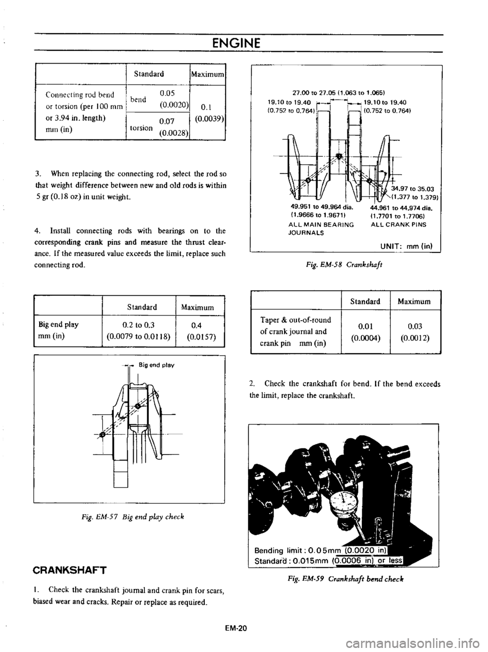
Standard
IMaXimum
Connecting
rod
bend
or
torsion
per
100
mm
or
3
94
in
length
mm
in
o
os
0
0020
0
07
0
0028
0
1
0
0039
bend
torsion
3
When
replacing
the
connecting
rod
select
the
rod
so
that
weight
difference
between
new
and
old
rods
is
within
S
gr
0
18
oz
in
unit
weight
4
Install
connecting
rods
with
bearings
on
to
the
corresponding
crank
pins
and
measure
the
thrust
clear
ance
If
the
measured
value
exceeds
the
limit
replace
such
connecting
rod
Stan
dard
Maximum
Big
end
play
mm
in
0
2
to
0
3
0
0079
to
0
Ql18
0
4
0
0IS7
l
8ig
end
plav
A
t
f
L
Fig
EM
57
Big
end
play
check
CRANKSHAFT
Check
the
crankshaft
journal
and
crank
pin
for
scars
biased
wear
and
cracks
Repair
or
replace
as
required
EM
20
27
00
to
27
05
1
063
to
1
065
19
1Ot01940
r
19
10t019
40
fO
752
to
0
764
Ii
10
75Z
to
0
764
I
c
1
r
1tf
1
I
J
X
I
34
97
to
35
03
t
11
377
to
1
379
49
951
to
49
964
dia
11
9666
to
1
96711
ALL
MAIN
BEARING
JOURNALS
Fig
EM
58
Crankshaft
Standard
Taper
out
of
round
of
crank
journal
and
crank
pin
mm
in
0
01
0
0004
44
961
to
44
974
die
11
7701
to
1
7706
ALL
CRANK
PINS
UNIT
ffim
in
Maximum
0
03
0
0012
2
Check
the
crankshaft
for
bend
If
the
bend
exceeds
the
limit
replace
the
crankshaft
Bending
limit
0
05mm
0
0020
in
Standaia
0
015mm
0
0006
in
or
less
Fig
EM
59
Crankshaft
bend
check
Page 361 of 513
ENGINE
MECHANICAL
Standard
Maximum
Crankshaft
bend
mm
in
0
05
0
0020
0
015
0
0006
Note
When
measuring
bend
use
a
dial
gauge
Bend
value
is
a
half
of
the
reading
obtained
when
the
crankshaft
is
turned
once
with
the
dial
gauge
applied
to
its
center
journal
3
After
regrinding
the
crankshaft
fmish
it
to
the
necessary
size
indicated
in
the
lists
on
pages
EM
25
by
using
an
adequate
undersize
bearing
according
to
the
extent
of
required
repair
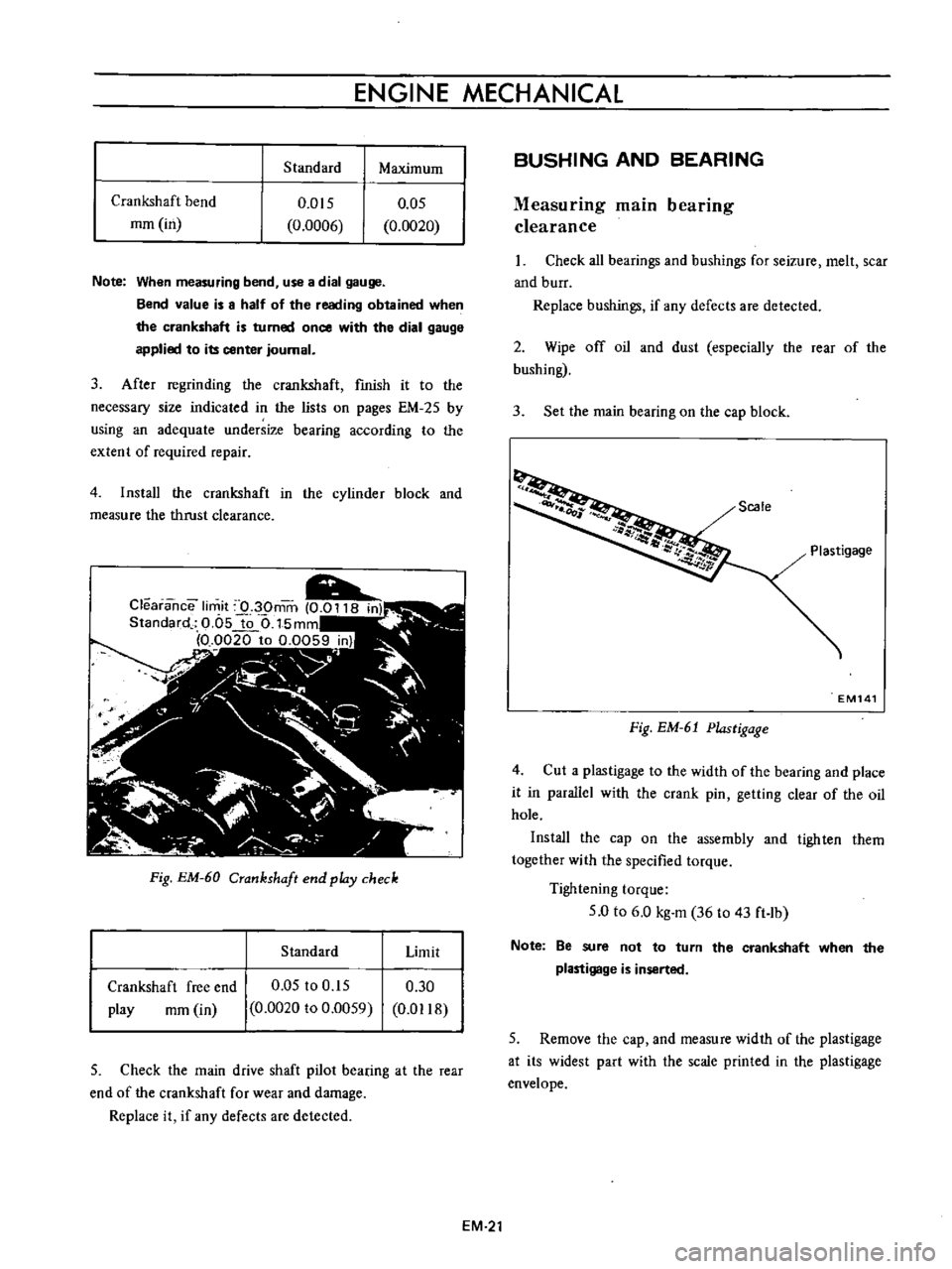
4
Install
the
crankshaft
in
the
cylinder
block
and
measure
the
thrust
clearance
Fig
EM
60
Crankshaft
end
pldy
check
Standard
Limit
Crankshaft
free
end
play
rom
in
0
05
to
0
15
0
0020
to
0
0059
0
30
0
D118
5
Check
the
main
drive
shaft
pilot
bearing
at
the
rear
end
of
the
crankshaft
for
wear
and
damage
Replace
it
if
any
defects
are
detected
BUSHING
AND
BEARING
Measuring
main
bearing
clearance
Check
all
bearings
and
bushings
for
seizure
melt
scar
and
burr
Replace
bushings
if
any
defects
are
detected
2
Wipe
off
oil
and
dust
especially
the
rear
of
the
bushing
3
Set
the
main
bearing
on
the
cap
block
Scale
Plastigage
EM141
Fig
EM
61
Plastigage
4
Cut
a
plastigage
to
the
width
of
the
bearing
and
place
it
in
parallel
with
the
crank
pin
getting
clear
of
the
oil
hole
Install
the
cap
on
the
assembly
and
tighten
them
together
with
the
specified
torque
Tightening
torque
5
0
to
6
0
kg
m
36
to
43
ft
lb
Note
Be
sure
not
to
turn
the
crankshaft
when
the
plastigage
is
inserted
5
Remove
the
cap
and
measure
width
of
the
plastigage
at
its
widest
part
with
the
scale
printed
in
the
plastigage
envelope
EM
21
Page 362 of 513
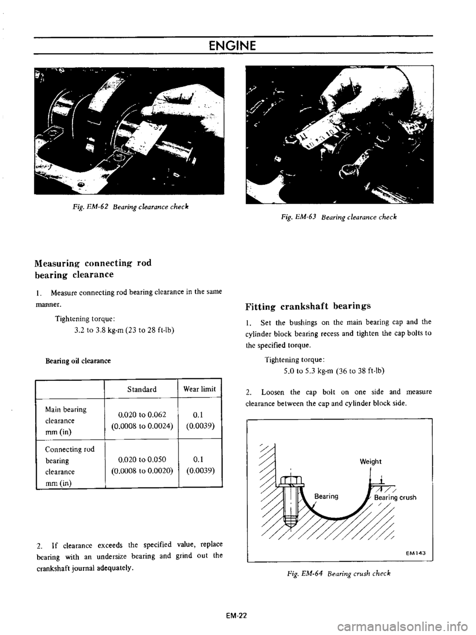
ENGINE
Pig
EM
62
Bearing
clearance
check
Measuring
connecting
rod
bearing
clearance
Measure
connecting
rod
bearing
clearance
in
the
same
manner
Tightening
torque
3
2
to
3
8
kg
m
23
to
28
ft
Ib
Bearing
oil
clearance
Standard
Wear
limit
Main
bearing
clearance
rom
in
0
020
to
0
062
0
0008
to
0
0024
0
1
0
0039
Connecting
rod
bearing
clearance
mm
in
0
020
to
0
050
0
0008
to
0
0020
0
1
0
0039
2
If
clearance
exceeds
the
specified
value
replace
bearing
with
an
undersize
bearing
and
grind
out
the
crankshaft
journal
adequately
Fig
EM
63
Bearing
clearance
check
Fitting
crankshaft
bearings
I
Set
the
bushings
on
the
main
bearing
cap
and
the
cylinder
block
bearing
recess
and
tighten
the
cap
bolts
to
the
specified
torque
Tightening
torque
5
0
to
5
3
kg
m
36
to
38
ft
lb
2
Loosen
the
cap
bolt
on
one
side
and
measure
clearance
between
the
cap
and
cylinder
block
side
n
n
u
ii
Bearing
6
Weight
EM143
Fig
EM
64
Bearing
crush
check
EM
22
Page 364 of 513
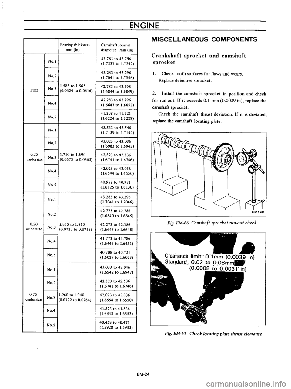
Bearing
thickness
mm
in
STD
I
No
1
I
No
2
I
I
I
1
585
to
1
565
No
3
0
0624
to
0
0616
I
No
4
I
No
5
I
NO
11
0
25
I
1
710
to
1
690
undersize
No
3
0
0673
to
0
0665
I
No
4
I
No
5
I
No
1
I
I
No
2
I
0
50
I
1
835
to
1
815
undersize
No
3
0
0722
to
0
0715
No
4
No
5
I
I
No
1
I
No
2
I
0
75
I
11
960
to
1
940
undersize
No
3
0
0772
to
0
0764
I
No
4
I
I
No
5
I
ENGINE
Camshaft
journal
diameter
mm
in
D
783
to
43
796
1
7237
to
1
7242
43
283
to
43
296
1
7041
to
1
7046
42
783
to
42
796
1
6844
to
1
6849
42
283
to
42
296
1
6647
to
1
6652
41
208
to
41
221
1
6224
to
1
6229
43
533
to
43
546
11
7139
to
1
7144
43
023
to
43
036
1
6983
to
1
6943
42
523
to
42
536
1
6741
to
1
6746
42
023
to
42
036
1
6544
to
1
6550
40
958
to
40
971
1
6t25
to
1
6
30
43
283
to
43
296
1
7041
to
1
7046
42
773
to
42
786
1
6840
to
1
6845
42
273
to
42
286
11
6643
to
1
6648
41
773
to
41
786
1
6446
to
1
6451
40
708
to
40
721
1
6027
to
1
6023
43
033
to
43
046
1
6942
to
1
6947
42
523
to
42
536
1
674t
to
1
6746
42
023
to
42
036
1
6554
to
1
6550
41
523
to
41
536
1
6348
to
1
6353
40
458
to
40
471
1
5928
to
1
5933
EM
24
MISCELLANEOUS
COMPONENTS
Crankshaft
sprocket
and
camshaft
sprocket
I
Check
tooth
surfaces
for
flaws
and
wears
Replace
defective
sprocket
2
Install
the
camshaft
sprocket
in
position
and
check
for
run
out
If
it
exceeds
0
1
mm
0
0039
in
replace
the
camshaft
sprocket
Check
the
camshaft
thrust
deviation
If
it
is
deviated
replace
the
camshaft
locating
plate
f
EMl48
Fig
EM
66
Camshaft
sprocket
run
out
check
Clearance
limit
0
Imm
0
0039
in
SJ
l
ldar
Q
0
02
to
0
08mm
0
0008
to
0
0031
in
Fig
EM
67
Check
locating
plate
thrust
clearance
Page 365 of 513
ENGINE
MECHANICAL
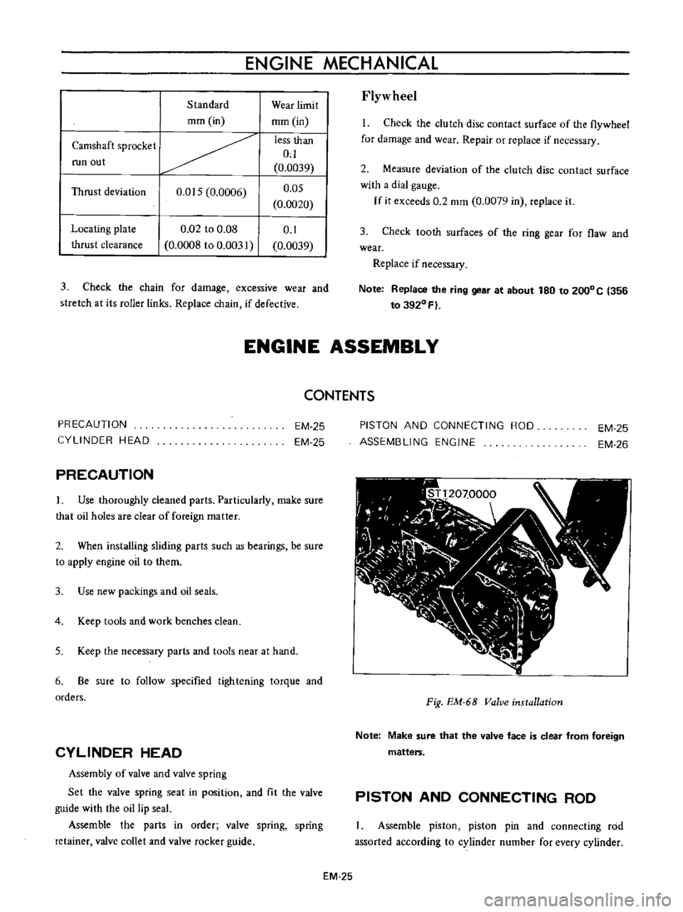
Standard
mm
in
Camshaft
sprocket
run
out
Thrust
deviation
O
OIS
0
0006
Locating
plate
thrust
clearance
0
02
to
0
08
0
0008
to
0
003
Wear
limit
mm
in
less
than
0
0
0039
O
OS
0
0020
0
1
0
0039
3
Check
the
chain
for
damage
excessive
wear
and
stretch
at
its
roller
links
Replace
chain
if
defective
Flyw
heel
I
Check
the
clutch
disc
contact
surface
of
the
flywheel
for
damage
and
wear
Repair
or
replace
if
necessary
2
Measure
deviation
of
the
clutch
disc
contact
surface
with
a
dial
gauge
If
it
exceeds
0
2
mm
0
0079
in
replace
it
3
Check
tooth
surfaces
of
the
ring
gear
for
flaw
and
wear
Replace
if
necessary
Note
Replace
the
ring
gear
at
about
180
to
2000C
356
to
3920
Fl
ENGINE
ASSEMBLY
PRECAUTION
CYLINDER
HEAD
PRECAUTION
CONTENTS
EM
25
EM
25
Use
thoroughly
cleaned
parts
Particularly
make
sure
that
oil
holes
are
clear
of
foreign
matter
2
When
installing
sliding
parts
such
as
bearings
be
sure
to
apply
engine
oil
to
them
3
Use
new
packings
and
oil
seals
4
Keep
tools
and
work
benches
clean
S
Keep
the
necessary
parts
and
tools
near
at
hand
6
Be
sure
to
follow
specified
tightening
torque
and
orders
CYLINDER
HEAD
Assembly
of
valve
and
valve
spring
Set
the
valve
spring
seat
in
position
and
fit
the
valve
guide
with
the
oil
lip
seal
Assemble
the
parts
in
order
valve
spring
spring
retainer
valve
collet
and
valve
rocker
guide
PISTON
AND
CONNECTING
ROO
ASSEMBLING
ENGINE
EM
25
EM
26
I
I
11
00
I
I
I
t
I
J
ftr
J
J
1
l
J
r
N
1
n
r
VI
I
I
C
I
L
I
Fig
EM
68
Valve
installation
Note
Make
sure
that
the
valve
face
is
clear
from
foreign
matters
PISTON
AND
CONNECTING
ROD
Assemble
piston
piston
pin
and
connecting
rod
assorted
according
to
cylinder
number
for
every
cylinder
EM
25
Page 367 of 513
ENGINE
MECHANICAL
3
Apply
engine
oil
to
the
main
bearing
surfaces
on
both
sides
of
the
cylinder
block
and
cap
Install
the
crankshaft
4
Install
the
main
bearing
cap
and
tighten
the
bolts
with
specified
torque
Tightening
torque
5
0
to
6
0
kg
m
36
to
43
ft
lb
Notes
a
Arrange
the
parts
so
that
the
arrow
mark
on
the
bearing
cap
is
faced
toward
the
front
of
the
engine
b
Prior
to
tightening
the
bearing
cap
bolts
place
the
bearing
cap
at
a
proper
position
by
shifting
the
crankshaft
in
the
axial
direction
c
Tighten
the
bearing
cap
bolts
gradually
in
separating
two
to
three
stages
and
outwardly
from
the
center
beari
ng
d
After
securing
the
bearing
cap
bolts
ascertain
that
the
crankshaft
can
be
easily
rotated
5
Make
sure
that
the
crankshaft
end
play
is
correct
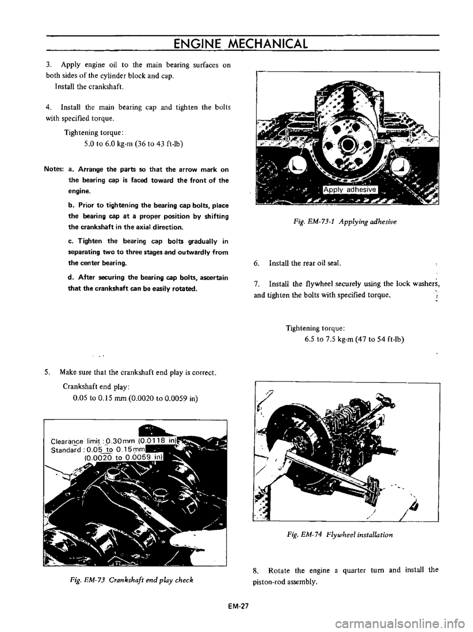
Crankshaft
end
play
0
05
to
0
15
rom
0
0020
to
0
0059
in
Fig
EM
73
Crankshaft
end
play
check
EM
27
Fig
EM
73
t
Applying
adhesive
6
Install
the
rear
oil
seal
7
Install
the
flywheel
securely
using
the
lock
washers
and
tighten
the
bolts
with
specified
torque
Tightening
torque
6
5
to
7
5
kg
m
47
to
54
ft
lb
Iii
Fig
EM
74
Flywheel
installation
8
Rotate
the
engine
a
quarter
turn
and
install
the
piston
rod
assembly
Page 368 of 513
ENGINE
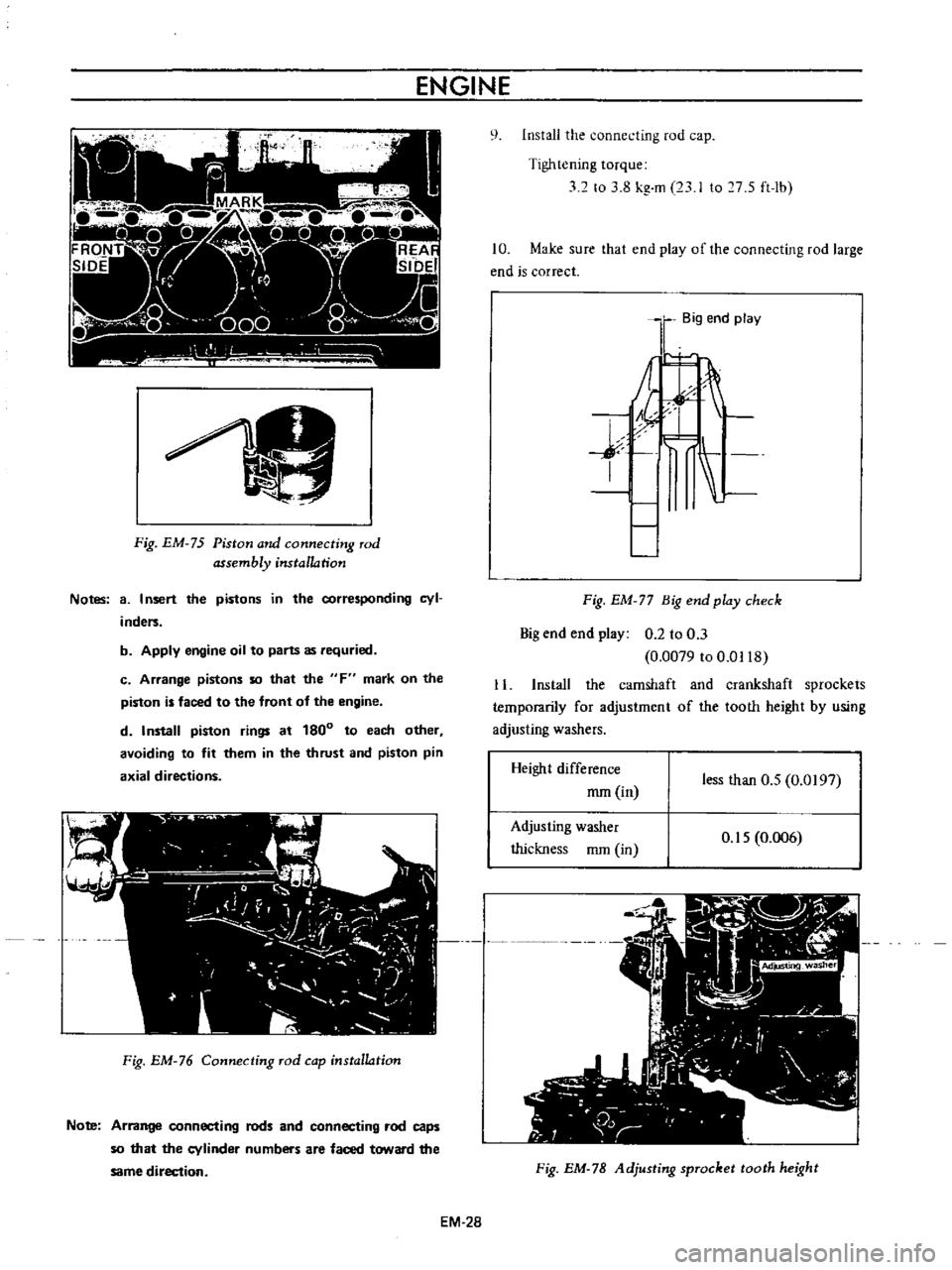
Fig
EM
75
Piston
and
connecting
rod
assembly
installation
Notes
8
I
nsert
the
pistons
in
the
corresponding
cyl
inders
b
Apply
engine
oil
to
parts
as
requried
c
Arrange
pistons
so
that
the
F
mark
on
the
piston
is
faced
to
the
front
of
the
engine
d
Install
piston
rings
at
180
to
each
other
avoiding
to
fit
them
in
the
thrust
and
piston
pin
axial
directions
Fig
EM
76
Connecting
rod
cap
installation
Note
Arrange
connecting
rods
and
connecting
rod
caps
so
that
the
cylinder
numbers
are
faced
toward
the
same
direction
EM
28
q
Install
the
connecting
rod
cap
Tightening
torque
32
to
3
8
kg
m
23
I
to
7
S
ft
lb
10
Make
sure
that
end
play
of
the
connecting
rod
large
end
is
correct
Big
end
play
j
I
Fig
EM
77
Big
end
play
check
Big
end
end
play
0
2
to
0
3
0
0079
to
0
0118
11
Install
the
camshaft
and
crankshaft
sprockets
temporarily
for
adjustment
of
the
tooth
height
by
using
adjusting
washers
Height
difference
mm
in
less
than
O
S
0
0197
Adjusting
washer
thickness
mm
in
O
IS
0
006
Fig
EM
78
Adjusting
sprocket
tooth
height
Page 369 of 513
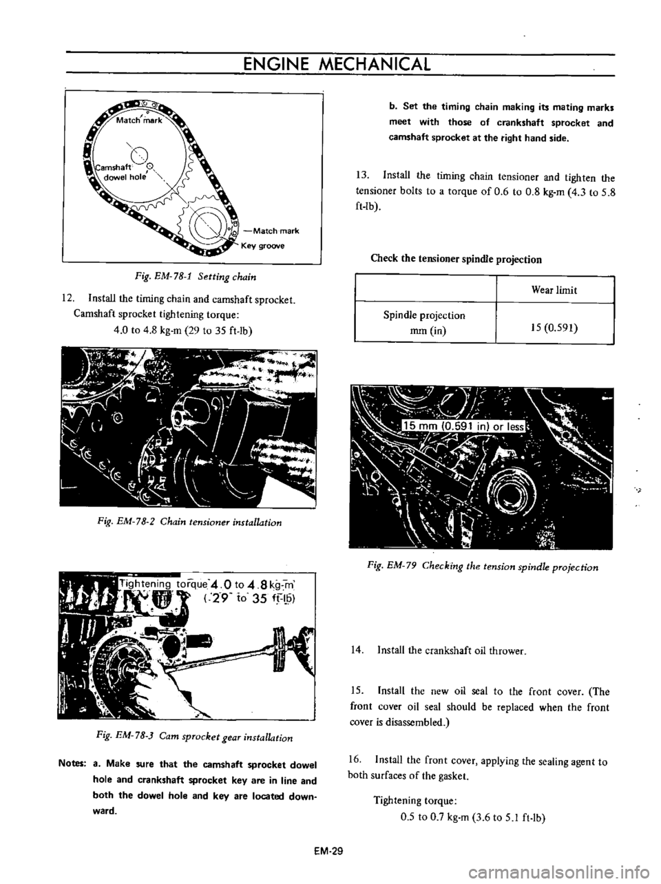
ENGINE
MECHANICAL
o
Match
mark
Key
groove
Fig
EM
78
1
Setting
chain
12
Install
the
timing
chain
and
camshaft
sprocket
Camshaft
sprocket
tightening
torque
4
0
to
4
8
kg
m
29
to
35
ft
lb
Fig
EM
78
2
Chain
tensioner
installation
Fig
EM
7B
Cam
sprocket
gear
installation
Notes
a
Make
sure
that
the
camshaft
sprocket
dowel
hole
and
crankshaft
sprocket
key
are
in
line
and
both
the
dowel
hole
and
key
are
located
down
ward
b
Set
the
timing
chain
making
its
mating
marks
meet
with
those
of
crankshaft
sprocket
and
camshaft
sprocket
at
the
right
hand
side
13
Install
the
timing
chain
tensioner
and
tighten
the
tensioner
bolts
to
a
torque
of
0
6
to
0
8
kg
m
4
3
to
5
8
ft
lb
Check
the
tensioner
spindle
projection
Wear
limit
Spindle
projection
mm
in
15
0
591
Fig
EM
79
Checking
the
tension
spindle
projection
14
Install
the
crankshaft
oil
thrower
15
Install
the
new
oil
seal
to
the
front
cover
The
front
cover
oil
seal
should
be
replaced
when
the
front
cover
is
disassembled
16
Install
the
front
cover
applying
the
sealing
agent
to
both
surfaces
of
the
gasket
Tightening
torque
0
5
to
0
7
kg
m
3
6
to
5
1
ft
lb
EM
29
Page 379 of 513
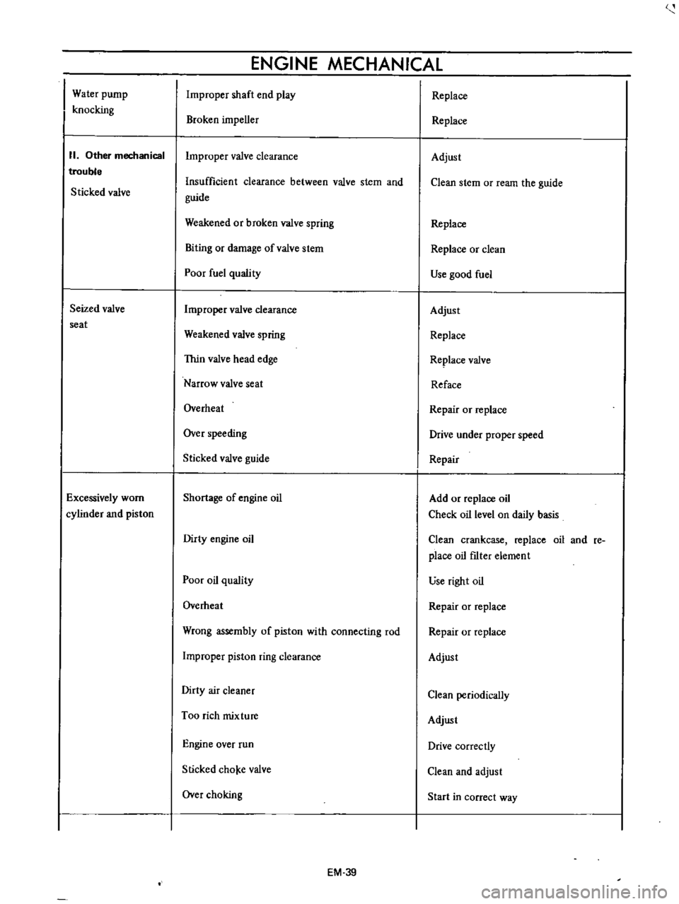
Water
pump
knocking
II
Other
mechanical
trouble
Sticked
valve
Seized
valve
seat
Excessively
worn
cylinder
and
piston
ENGINE
MECHANICAL
Improper
shaft
end
play
Broken
impeller
Improper
valve
clearance
Insufficient
clearance
between
valve
stem
and
guide
Weakened
or
broken
valve
spring
Biting
or
damage
ofvalve
stem
Poor
fuel
quality
Improper
valve
clearance
Weakened
valve
spring
Thin
valve
head
edge
Narrow
valve
seat
Overheat
Over
speeding
Sticked
valve
guide
Shortage
of
engine
oil
Dirty
engine
oil
Poor
oil
quality
Overheat
Wrong
assembly
of
piston
with
connecting
rod
Improper
piston
ring
clearance
Dirty
air
cleaner
Too
rich
mixture
Engine
over
run
Slicked
cho
e
valve
Over
choking
EM
39
Replace
Replace
Adjust
Clean
stem
or
ream
the
guide
Replace
Replace
or
clean
Use
good
fuel
Adjust
Replace
Replace
valve
Reface
Repair
or
replace
Drive
under
proper
speed
Repair
Add
or
replace
oil
Check
oil
level
on
daily
basis
Clean
crankcase
replace
oil
and
re
place
oil
fIlter
element
use
right
oil
Repair
or
replace
Repair
or
replace
Adjust
Clean
periodically
Adjust
Drive
correctly
Clean
and
adjust
Start
in
correct
way