length DATSUN B110 1973 Service User Guide
[x] Cancel search | Manufacturer: DATSUN, Model Year: 1973, Model line: B110, Model: DATSUN B110 1973Pages: 513, PDF Size: 28.74 MB
Page 147 of 513
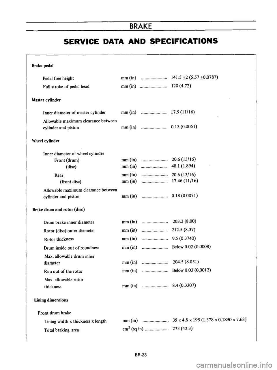
BRAKE
SERVICE
DATA
AND
SPECIFICATIONS
Brake
pedal
Pedal
free
height
Full
stroke
of
pedal
head
Master
cylinder
mm
in
mm
in
141
5
t2
5
57
to
0787
120
4
72
17
5
11
16
Inner
diameter
of
master
cylinder
mm
in
Allowable
maximum
clearance
between
cylinder
and
piston
mm
in
Wheel
cylinder
Inner
diameter
of
wheel
cylinder
Front
drum
disc
Rear
front
disc
Allowable
maximum
clearance
between
cylinder
and
piston
Brake
drum
and
rotor
disc
Drum
brake
inner
diameter
Rotor
disc
outer
diameter
Rotor
thickness
Drum
inside
out
of
roundness
Max
allowable
drum
inner
diameter
Run
out
of
the
rotor
Max
allowable
rotor
thickness
Lining
dimensions
Front
drum
brake
Lining
width
x
thickness
x
length
Total
braking
area
0
13
0
0051
mm
in
mm
in
mm
in
mm
in
20
6
13
16
48
1
1
894
20
6
13
16
1746
11
16
mm
in
0
18
0
0071
mm
in
mm
in
mm
in
mm
in
203
2
8
00
212
5
837
9
5
03740
Below
0
Q2
0
0008
mm
in
mm
in
204
5
8
051
Below
0
03
0
0012
mm
in
8
4
03307
mm
in
cm2
sq
in
35
x
4
8
x
195
1
378
x
0
1890
x
7
68
273
423
BR
2J
Page 148 of 513
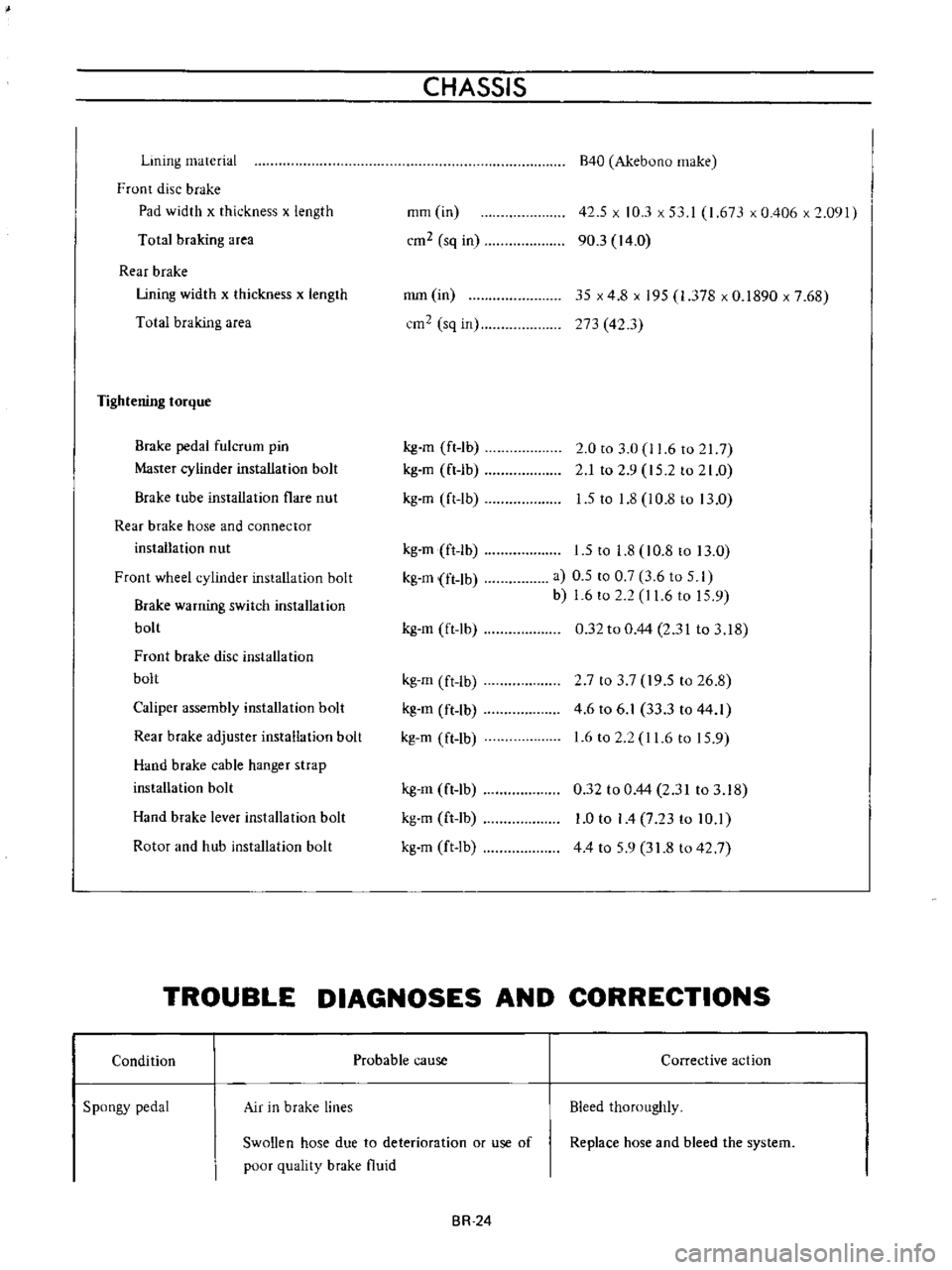
Lining
material
Front
disc
brake
Pad
width
x
thickness
x
length
Total
braking
area
Rear
brake
Lining
width
x
thickness
x
length
Total
braking
area
Tightening
torque
Brake
pedal
fulcrum
pin
Master
cylinder
installation
bolt
Brake
tube
installation
flare
nut
Rear
brake
hose
and
connector
installation
nut
Front
wheel
cylinder
installation
bolt
Brake
warning
switch
installation
bolt
Front
brake
disc
installation
bolt
Caliper
assembly
installation
bolt
Rear
brake
adjuster
installation
bolt
Hand
brake
cable
hanger
strap
installation
bolt
Hand
brake
lever
installation
bolt
Rotor
and
hub
installation
bolt
CHASSIS
mm
in
cm2
sq
in
mm
in
cm2
sq
in
kg
m
ft
1b
kg
m
ft
lb
kg
m
ft
lb
kg
m
ft
lb
kg
m
ft
lb
kg
m
ft
lb
kg
m
ft
lb
kg
m
ft
lb
kg
m
ft
lb
kg
m
ft
lb
kg
m
ft
lb
kg
m
ft
Ib
B40
Akebuno
make
42
5
x
10
3
x
53
I
1
673
x
0
406
x
2
091
90
3
14
0
35
x
4
8
x
195
1
378
x
0
1890
x
7
68
273
42
3
2
0
to
3
0
11
6
to
217
2
1
to
2
9
15
2
to
21
0
1
5
to
1
8
l
0
8
to
13
0
1
5
to
1
8
10
8
to
13
0
a
0
5
to
0
7
3
6
to
5
I
b
1
6
to
2
2
I
1
6
to
15
9
0
32
to
0
44
2
31
to
3
18
2
7
to
3
7
19
5
to
26
8
4
6
to
6
1
33
3
to
44
1
1
6
to
2
2
11
6
to
15
9
0
32
to
0
44
2
31
to
3
18
1
0
to
I
4
7
23
to
10
1
44
to
59
31
8
to
42
7
TROUBLE
DIAGNOSES
AND
CORRECTIONS
Condition
Spongy
pedal
Air
in
brake
lines
Probable
cause
Swollen
hose
due
to
deterioration
or
use
of
poor
quality
brake
fluid
BR
24
Corrective
action
Bleed
thoroughly
Replace
hose
and
bleed
the
system
Page 171 of 513
STEERING
The
jacket
tube
is
of
a
mesh
and
a
part
of
which
is
punched
in
rhombus
forming
an
energy
absorbing
part
of
the
collapsible
steering
Upper
and
lower
guide
tubes
two
guide
tubes
joined
with
polyacetal
resin
are
inserted
into
the
mesh
tube
so
STEERING
POST
CLAMP
that
an
energy
generated
by
collision
can
be
absorbed
as
smoothly
as
possible
with
a
low
load
The
guide
tubes
function
as
a
guide
for
mesh
tube
while
the
mesh
tube
is
collapsed
and
improve
bending
rigidity
of
the
entire
jacket
tube
1
1
Plastic
pin
I
2
I
Clamp
1
3
I
Sliding
block
Fig
ST
19
Steering
post
clamp
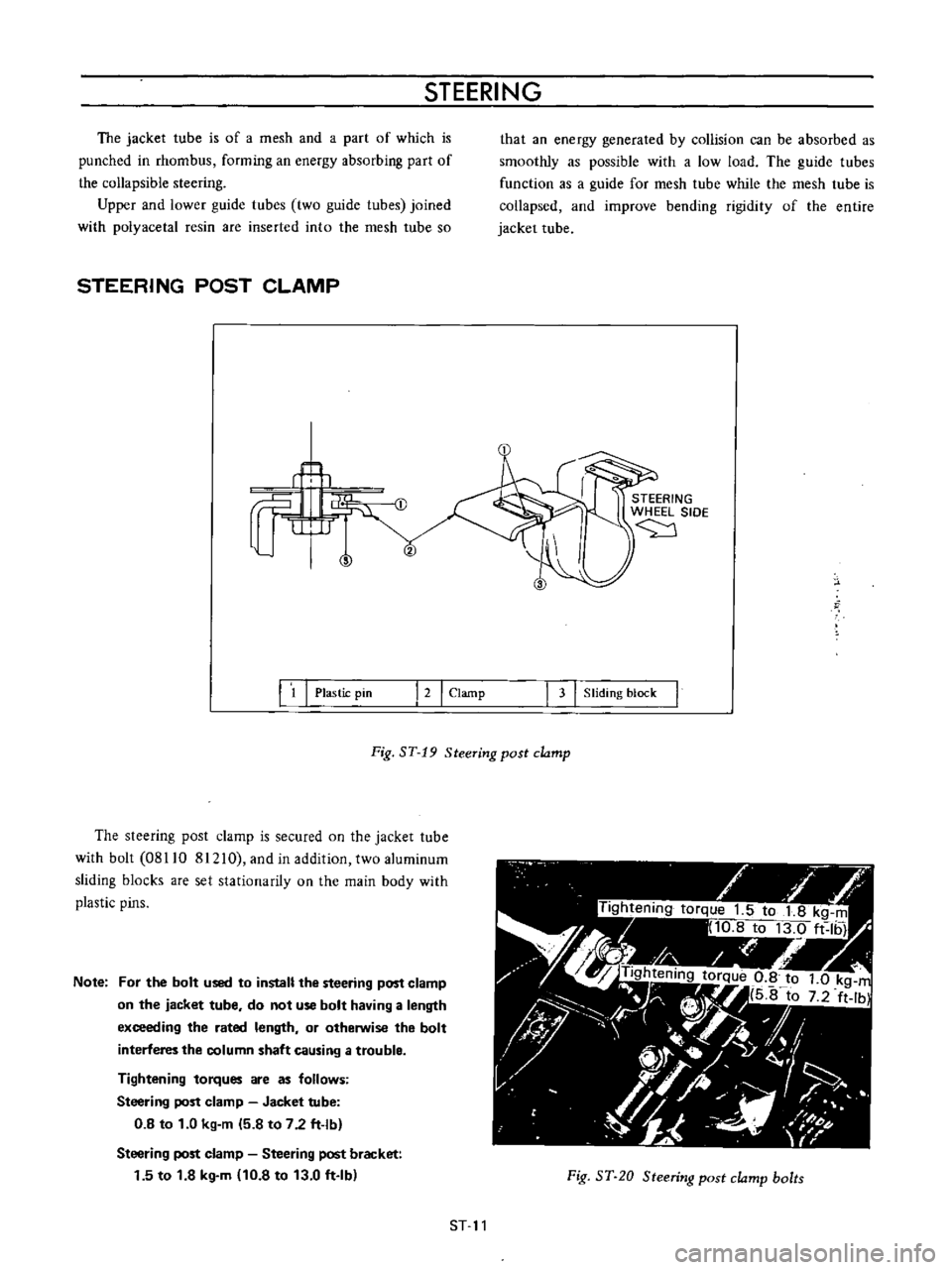
The
steering
post
clamp
is
secured
on
the
jacket
tube
with
bolt
08110
81210
and
in
addition
two
aluminum
sliding
blocks
are
set
stationarity
on
the
main
body
with
plastic
pins
Note
For
the
bolt
used
to
install
the
steering
post
clamp
on
the
jacket
tube
do
not
use
bolt
having
a
length
exceeding
the
rated
length
or
otherwise
the
bolt
interferes
the
column
shaft
causing
a
trouble
Tightening
torques
are
as
follows
Steering
post
clamp
Jacket
tube
0
8
to
1
0
kg
m
5
8
to
7
2
ft
lb
Steering
post
clamp
Steering
post
bracket
1
5
to
1
8
kg
m
10
8
to
13
0
ft
Ib
Fig
ST
20
Steering
post
clamp
bolts
ST
11
Page 172 of 513
CHASSIS
The
sliding
block
is
secured
on
the
steering
post
bracket
with
bolts
upper
half
of
the
steering
column
is
supported
on
the
bracket
and
thus
the
steering
post
clamp
is
installed
on
the
body
When
a
large
impact
is
applied
from
the
driver
side
the
plastic
pins
are
cut
off
and
leaving
the
sliding
block
in
the
steering
post
bracket
side
the
clamp
proper
is
disengaged
downward
together
with
the
jacket
tube
For
any
force
applied
from
front
direction
of
the
vehicle
the
steering
post
clamp
sliding
block
does
not
move
rearward
This
construction
is
called
One
way
slide
system
and
with
this
construction
projection
of
the
column
shaft
toward
the
driver
is
prevented
completely
COLUMN
BEARING
b
ciJ
STEERING
WHEEL
SIDE
1
Jacket
tube
2
Washer
3
Snap
ring
4
Column
bush
5
ColurtlO
shaft
Fig
ST
21
Column
bearing
Construction
of
the
column
shaft
upper
bearing
is
as
such
that
both
radial
and
thrust
forces
are
absorbed
DISASSEMBLY
First
remove
the
snap
ring
from
the
upper
surface
of
the
column
bushing
Thereafter
general
instructions
for
ordinary
steering
apply
Inspect
and
adjust
the
sector
shaft
worm
ball
nut
unit
adjust
screw
unit
worm
bearing
and
other
relative
parts
in
accordance
with
the
instructions
for
ordinary
type
steering
INSPECTION
Inspect
the
parts
such
as
column
shaft
jacket
tube
etc
which
are
used
to
absorb
energy
in
accordance
with
the
following
instructions
Check
the
column
shaft
plastic
pin
for
breakdown
2
Check
the
steering
lock
collar
for
warping
and
screw
for
breakdown
3
Measure
tolal
length
of
the
jacket
tube
Replace
if
contracted
However
when
tube
collapse
is
within
3
mm
0
1181
in
adjustmenl
by
means
of
bushing
is
also
possible
4
Check
the
steering
post
clamp
sliding
block
for
tightness
5
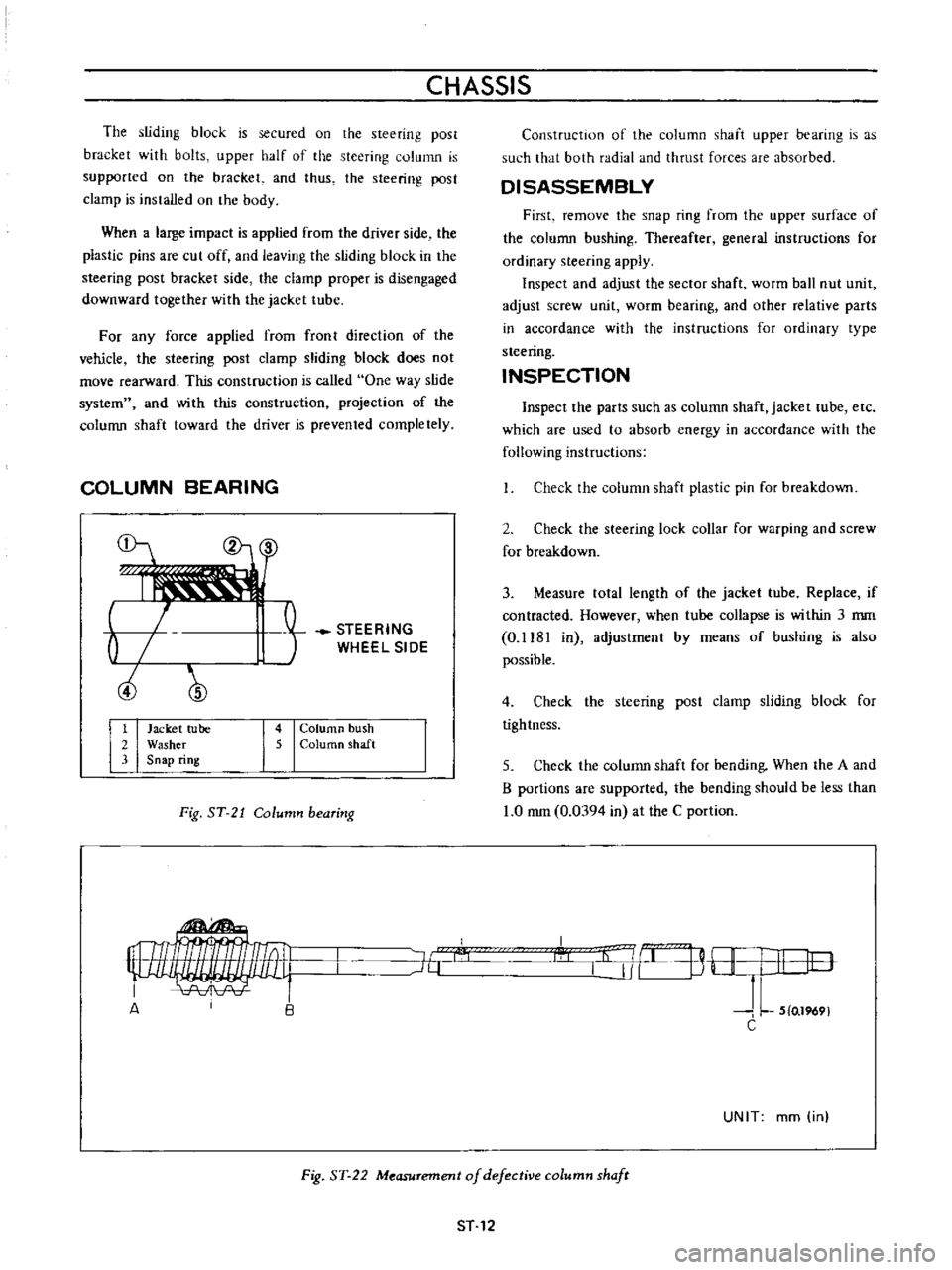
Check
the
column
shaft
for
bending
When
the
A
and
B
portions
are
supported
the
bending
should
be
less
than
1
0
mm
0
0394
in
at
the
C
portion
I
l
j
B
H
I
I
lO
J
L
5
0
1969
C
J6
A
UNIT
mm
in
Fig
ST
22
Measurement
of
defective
column
shafr
ST
12
Page 173 of 513
STEERING
REASSEMBLY
Adjust
alignment
and
install
the
worm
shaft
and
jacket
tube
on
the
housing
2
Apply
bearing
grease
to
the
interior
sufficiently
and
screw
the
column
bushing
above
the
rated
position
3
Apply
washer
and
apply
the
snap
ring
to
the
groove
correctly
and
securely
4
Return
the
column
bushing
allowing
the
top
surface
of
the
bushing
coming
into
contact
wi
th
the
lower
surface
of
the
washer
adjust
the
clearance
to
less
than
1
0
mm
0
0394
in
and
adjust
the
bushing
position
correctly
so
that
column
shaft
turning
torque
is
the
rated
value
Note
If
the
clearance
is
too
small
the
steering
becomes
heavy
5
Line
up
the
jacket
tube
upper
end
to
the
groove
on
the
outer
circumference
of
the
column
bushing
and
securely
caulk
two
symmetrical
positions
on
the
circum
ference
When
caulked
securely
make
sure
that
inner
diameter
of
the
jacket
tube
is
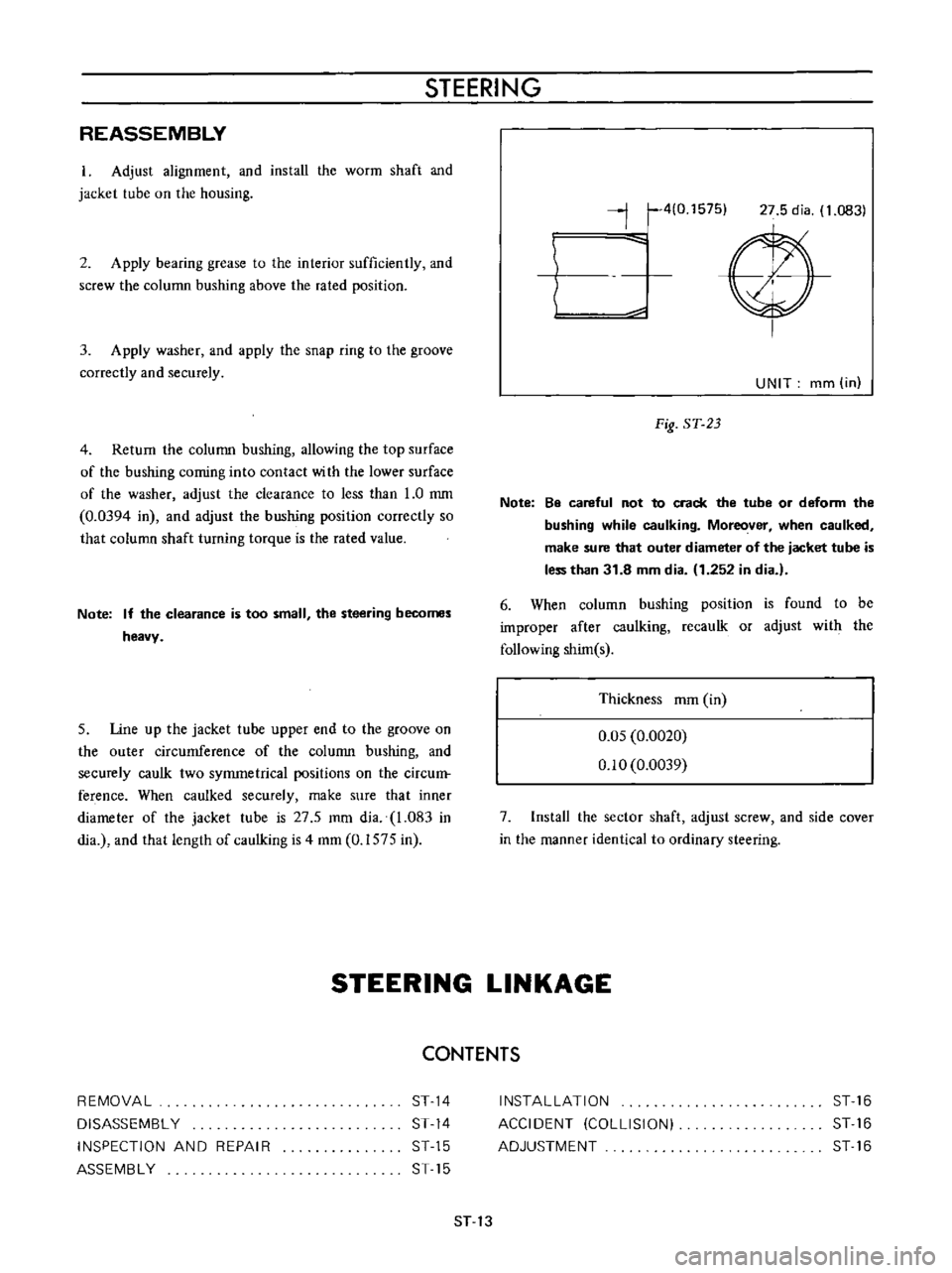
27
5
mm
dia
1
083
in
dia
and
that
length
of
caulking
is
4
mm
0
1575
in
j
410
1575
27
5
dia
1
0831
V
UNIT
mm
in
Fig
ST
23
Note
Be
careful
not
to
crack
the
tube
or
deform
the
bushing
while
caulking
Moreover
when
caulked
make
sure
that
outer
diameter
of
the
jacket
tube
is
less
than
31
8
mm
dia
1
252
in
dia
6
When
column
bushing
position
is
found
to
be
improper
after
caulking
recaulk
or
adjust
with
the
following
shim
s
Thickness
mm
in
0
05
0
0020
0
10
0
0039
7
Install
the
sector
shaft
adjust
screw
and
side
cover
in
the
manner
identical
to
ordinary
steering
STEERING
LINKAGE
CONTENTS
REMOVAL
DISASSEMBl
Y
INSPECTION
AND
REPAIR
ASSEMBl
Y
ST
14
ST
14
ST
15
ST
15
INSTAllATION
ACCIDENT
COLLISION
ADJUSTMENT
ST
16
ST
16
ST
16
ST
13
Page 176 of 513
CHASSIS
The
following
tightening
torque
of
nuts
shall
be
adopted
Ball
stud
nut
3
0
to
5
0
kg
m
21
7
to
36
2
ft
lb
Gear
arm
nut
14
kg
m
101
ft
lb
Idler
arm
nut
57
to
6
3
kg
m
41
2
to
45
6
ft
lb
2
Assembly
of
the
idler
assembly
is
accomplished
as
follows
I
Apply
soap
water
on
the
outer
circumference
of
bushing
Press
the
bushing
into
the
idler
arm
carefully
until
the
bushing
protrudes
equally
at
the
both
sides
2
Fit
idler
arm
body
in
the
rubber
bushing
Keep
the
idler
arm
center
line
in
parallel
with
the
chassis
center
line
INSTALLATION
Installation
can
be
accomplished
in
the
reverse
order
of
removal
Pay
attention
to
the
following
points
Set
the
length
of
both
side
rods
to
296
8
mm
11
69
in
It
should
be
done
between
the
ball
stud
centers
2
Check
wheel
alignment
and
if
necessary
adjust
it
ACCIDENT
COLLISION
When
accident
collision
occurs
unfortunately
and
the
vehicle
especially
its
front
unit
is
damaged
conduct
inspection
in
accordance
with
the
following
instruction
Inspect
the
steering
system
particularly
carefully
because
it
is
a
very
important
unit
for
driving
I
Check
both
side
steering
angles
for
correct
balance
2
With
the
tires
positioned
at
neutral
steering
wheel
bar
for
correct
position
check
the
l
3
Operate
the
steering
system
and
check
it
for
sliding
noise
4
Check
the
operation
for
smoothness
l
5
Check
the
side
rod
and
cross
rod
for
bending
6
Check
the
gear
arm
for
crack
7
Check
the
gear
housing
tiglltening
bolt
for
slackness
and
installation
boss
for
crack
8
Check
the
sector
shaft
serration
for
twisting
9
Check
the
sector
gear
for
crack
10
Check
the
ball
screw
for
pitting
II
Check
the
column
shaft
for
bending
crack
and
sliding
scar
12
Check
the
jacket
tube
for
bending
13
Check
the
steering
post
clamp
for
existance
of
column
offset
14
Check
the
side
member
gear
housing
installation
unit
for
deformation
IS
Check
the
portion
of
the
steering
post
bracket
installed
on
the
steering
post
clamp
for
correct
installation
AD
JUSTMENT
I
Toe
in
The
procedure
of
toe
in
adjustment
is
outlined
in
section
FRONT
AXLE
AND
FRONT
SUSPENSION
2
Steering
angle
Under
the
specified
load
4
passengers
adjust
the
stopper
bolt
of
the
knuckle
arm
so
that
the
inner
wheel
has
an
angle
of
430
Note
Specified
steering
angle
of
wheel
is
430
for
inner
wheel
and
36005
for
outer
wheel
ST
16
Page 177 of 513
STEERING
SERVICE
DATA
AND
SPECIFICATIONS
Type
Gear
ratio
Steering
wheel
diameter
Oil
capacity
Steering
angle
inner
wheel
outer
wheel
Play
steering
wheel
Standard
thickness
of
worrn
bearing
shims
Initial
turning
torque
of
column
assembly
Clearance
of
adjusting
screw
to
sector
shaft
Length
of
side
rod
Tightening
torque
Steering
wheel
lock
nut
Steering
post
clamp
to
steering
post
bracket
bolls
Collapsible
Steering
column
hole
cover
bolts
Column
to
gear
housing
bolts
Side
cover
to
gear
housing
bolts
Adjusting
screw
lock
nut
Sector
shaft
to
pitman
arm
nut
Gear
housing
to
side
main
bar
bolts
and
nuts
Idler
arm
nut
Recirculating
ball
type
mm
in
L
US
pt
Imp
pt
15
I
I
400
157
0
24
I
2
3
8
430
360
mm
in
20
to
25
0
787
to
0
984
mm
in
0
5
0
0197
kg
em
in
oz
2
0
to
5
0
27
8
to
69
4
mrn
in
mm
in
0
05
0
0020
296
8
11
69
kg
m
ft
lb
3
0
to
3
5
217
to
25
3
kg
m
ft
lb
kg
m
ft
Ib
kg
m
ft
lb
kg
m
ft
lb
kg
m
ft
lb
kg
m
ft
lb
kg
m
ft
lb
0
8
to
1
0
5
8
to
7
2
1
5
to
1
8
10
8
to
13
0
8
to
1
0
5
8
to
7
2
1
5
to
2
5
10
8
to
18
1
I
7
to
2
8
12
3
to
20
2
2
0
to
3
0
14
5
to
21
7
14
101
kg
m
ft
lb
kg
m
ft
lb
1
9
to
2
6
13
7
to
18
8
57
to
6
3
41
2
to
45
6
Idler
arm
to
side
main
bar
bolts
and
nuts
kg
m
ft
Ib
Ball
stud
nuts
kg
m
ft
lb
Side
rod
bar
lock
nuts
kg
m
ft
lb
1
9
to
2
6
13
7
to
18
8
3
0
to
5
0
21
7
to
36
2
8
0
to
10
0
57
8
to
72
3
ST
17
Page 205 of 513
BODY
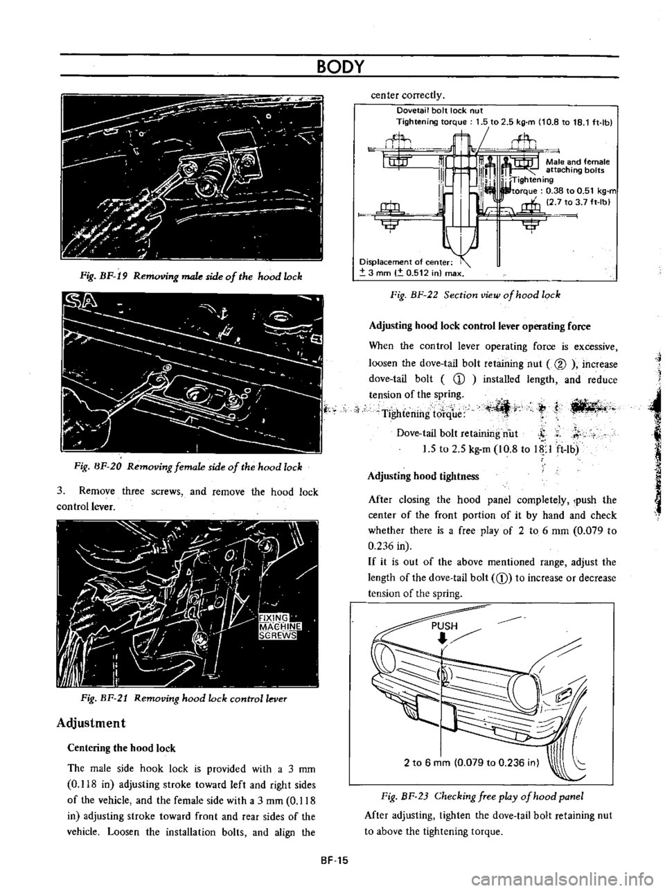
Fig
BF
19
R
g
male
side
of
the
hood
lock
Fig
BF
20
Removing
female
side
of
the
hood
lock
3
Remove
three
screws
and
remove
the
hood
lock
control
lever
Fig
BF
21
Removing
hood
lock
control
lever
Adjustment
Centering
the
hood
lock
The
male
side
hook
lock
is
provided
with
a
3
mm
0
118
in
adjusting
stroke
toward
left
and
right
sides
of
the
vehicle
and
the
female
side
with
a
3
rnm
0
118
in
adjusting
stroke
toward
front
and
rear
sides
of
the
vehicle
Loosen
the
installation
bolts
and
align
the
center
correctly
Dovetail
bolt
lock
nut
Tightening
torque
1
5
to
2
5
kg
m
10
8
to
18
1
ft
lb
flL
t1t
m
m
Male
and
female
111
l
111m
attaching
bol
W
TIghtening
I
lb
I
I
torque
0
38
to
0
51
kg
m
l
i
2
7
to
3
7
ft
Ibl
j
rffi
u
Ilillr
iji
Displacement
of
center
3
mm
0
512
in
max
Fig
BF
22
Section
view
of
hood
lock
Adjusting
hood
lock
control
lever
operating
force
When
the
control
lever
operating
force
is
excessive
loosen
the
dove
tail
bolt
retaining
nut
@
increase
dove
tail
bolt
CD
installed
length
and
reduce
tension
of
the
spring
Tightening
tore
ue
t
I
ili
4r
ti
llt4
t
j
Dove
tail
bolt
retaining
nut
S
r
1
5
to
2
5
kg
m
10
8
to
Up
ft
lb
Adjusting
hood
tightness
After
closing
the
hood
panel
completely
push
the
center
of
the
front
portion
of
it
by
hand
and
check
whether
there
is
a
free
play
of
2
to
6
mm
0
079
to
0
236
in
If
it
is
out
of
the
above
mentioned
range
adjust
the
length
of
the
dove
tail
bolt
CD
to
increase
or
decrease
tension
of
the
spring
2
to
6
mm
0
079
to
0
236
inl
Fig
BF
23
Checking
free
play
of
hood
panel
After
adjusting
tighten
the
dove
tail
bolt
retaining
nut
to
above
the
tightening
torque
SF
15
Page 241 of 513
INSPECTION
Referring
to
the
wiring
diagram
check
the
wiring
harness
for
connection
with
electrical
equipment
and
connector
for
conned
ion
and
installation
When
checking
the
wiring
harness
note
the
following
matters
Connected
unit
should
not
be
loose
rusted
or
contaminated
2
Cable
insulator
cover
should
not
be
damaged
crack
ed
or
insulating
material
should
not
be
deteriorated
3
For
those
parts
which
are
grounded
through
the
installation
bolts
the
bolts
should
be
in
contact
with
the
body
completely
so
that
continuity
is
provided
in
between
the
body
and
bolts
4
Terminals
of
unit
through
which
current
flows
should
not
come
into
contact
with
other
metal
parts
5
No
erroneous
connection
should
be
present
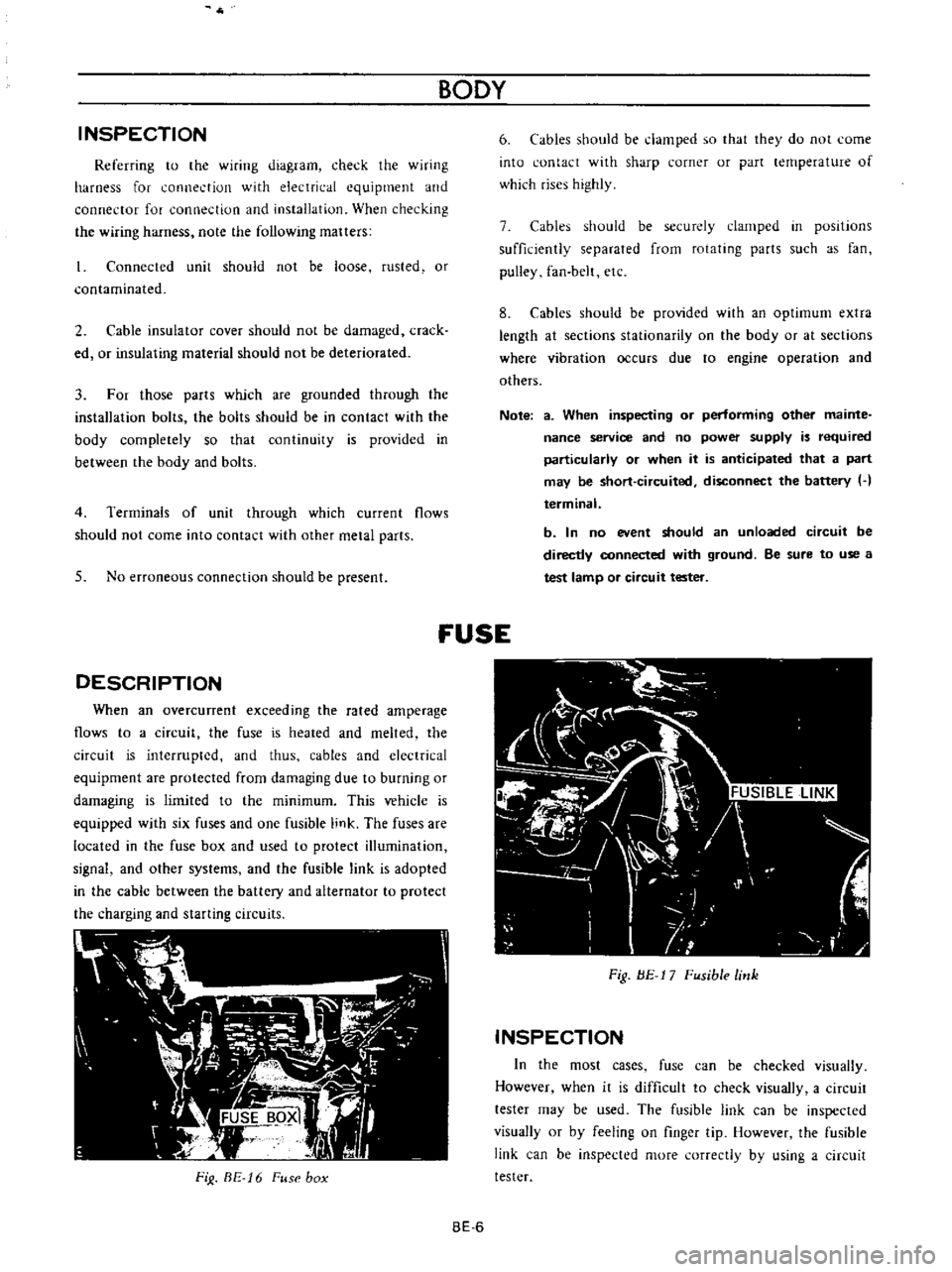
DESCRIPTION
When
an
overcunent
exceeding
the
rated
amperage
flows
to
a
circuit
the
fuse
is
heated
and
melted
the
circuit
is
interrupted
and
thus
cables
and
electrical
equipment
are
protected
from
damaging
due
to
burning
or
damaging
is
limited
to
the
minimum
This
vehicle
is
equipped
with
six
fuses
and
one
fusible
link
The
fuses
are
located
in
the
fuse
box
and
used
to
protect
illumination
signal
and
other
systems
and
the
fusible
link
is
adopted
in
the
cable
between
the
battery
and
alternator
to
protect
the
charging
and
starting
circuits
FiJ
BE
16
Fuse
box
BODY
6
Cables
should
be
damped
so
that
they
do
not
come
into
contact
with
sharp
corner
or
part
lernperature
of
which
rises
highly
7
Cables
should
be
securely
clamped
in
posItions
sufficiently
separated
from
rotating
parts
such
as
fan
pulley
fan
belt
etc
8
Cables
should
be
provided
with
an
optimum
extra
length
at
sections
stationarity
on
the
body
or
at
sections
where
vibration
occurs
due
to
engine
operation
and
others
Note
a
When
inspecting
or
performing
other
mainte
nance
service
and
no
power
supply
is
required
particularly
or
when
it
is
anticipated
that
a
part
may
be
short
circuited
disconnect
the
battery
H
terminal
b
In
no
event
should
an
unloaded
circuit
be
directly
connected
with
ground
Be
sure
to
use
a
test
lamp
or
circuit
tester
fUSE
Fig
BE
17
Fusible
link
INSPECTION
In
the
most
cases
fuse
can
be
checked
visually
However
when
it
is
difficult
to
check
visually
a
circuit
tester
may
be
used
The
fusible
link
can
be
inspected
visually
or
by
feeling
on
finger
tip
However
the
fusible
link
can
be
inspected
more
correctly
by
using
a
circuit
tester
BE
6
Page 326 of 513
EMISSION
CONTROL
AND
TUNE
UP
Appearance
1
First
inspect
whether
vacuum
hoses
are
connected
to
correct
positions
2
Inspect
hoses
for
cracks
distortion
or
plugging
Checking
of
vacuum
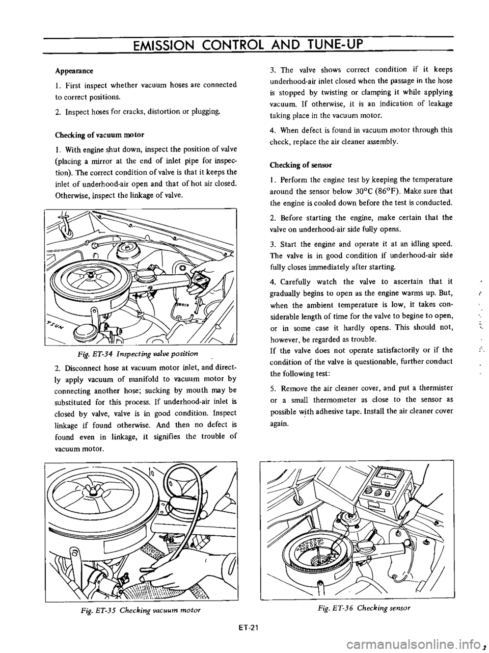
motor
I
With
engine
shut
down
inspect
the
position
of
valve
placing
a
mirror
at
the
end
of
inlet
pipe
for
inspec
tion
The
correct
condition
of
valve
is
that
it
keeps
the
inlet
of
underhood
air
open
and
that
of
hot
air
closed
Otherwise
inspect
the
linkage
of
valve
Fig
ET
34
Inspecting
valve
position
2
Disconnect
hose
at
vacuum
motor
inlet
and
direct
ly
apply
vacuum
of
manifold
to
vacuum
motor
by
connecting
another
hose
sucking
by
mouth
may
be
substituted
for
this
process
If
underhood
air
inlet
is
closed
by
valve
valve
is
in
good
condition
Inspect
linkage
if
found
otherwise
And
then
no
defect
is
found
even
in
linkage
it
signifies
the
trouble
of
vacuum
motor
Fig
ET
35
Checking
vacuum
motor
ET
21
3
The
valve
shows
correct
condition
if
it
keeps
underhood
air
inlet
closed
when
the
passage
in
the
hose
is
stopped
by
twisting
or
clamping
it
while
applying
vacuum
If
otherwise
it
is
an
indication
of
leakage
taking
place
in
the
vacuum
motor
4
When
defect
is
found
in
vacuum
motor
through
this
check
replace
the
air
cleaner
assembly
Checking
of
sensor
I
Perform
the
engine
test
by
keeping
the
temperature
around
the
sensor
below
300C
860F
Make
sure
that
the
engine
is
cooled
down
before
the
test
is
conducted
2
Before
starting
the
engine
make
certain
that
the
valve
on
underhood
air
side
fully
opens
3
Start
the
engine
and
operate
it
at
an
idling
speed
The
valve
is
in
good
condition
if
underhood
air
side
fully
closes
immediately
after
starting
4
Carefully
watch
the
valve
to
ascertain
that
it
gradually
begins
to
open
as
the
engine
warms
up
But
when
the
ambient
temperature
is
low
it
takes
con
siderable
length
of
time
for
the
valve
to
begine
to
open
or
in
some
case
it
hardly
opens
This
should
not
however
be
regarded
as
trouble
If
the
valve
does
not
operate
satisfactorily
or
if
the
condition
of
the
valve
is
questionable
further
conduct
the
following
test
5
Remove
the
air
cleaner
cover
and
put
a
thermister
or
a
small
thermometer
as
close
to
the
sensor
as
possible
with
adhesive
tape
Install
the
air
cleaner
cover
again
Fig
ET
36
Checking
sensor
1